Creation of Column Schedule and Drawing Template using AutoCad
1) Create a column schedule as shown in the figure.
Note: Create a column schedule with the help of lines. Also, insert text with the help of Dtext command or Single Line text.
Hint: Use font name: romans.shx; Height: 8”, Justify: Left
SOFTAWARE USED : AUODESK AUTOCAD 2021
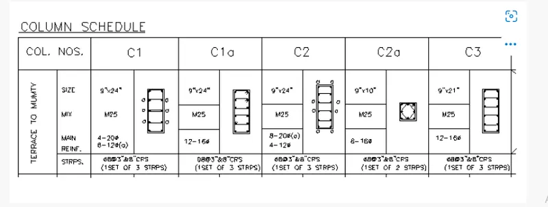
AIM:To prepare the column schedule.
Procedure:
- First the open the software
- Give the command QNEW and press the ENTERE key
- Click on imperical templete
- Select ADVANCE SETUP
- Unit : Engineering, precision :0.00
- Angle :decimal degree , precision :0.00
- Angle measure : East
- Angle direction : closkwise
- Area : 20*20
- And finished , Lets start
- Command : D (dimension style manager )
- Click on :MODIFY
- Select : TEXT option
- Selct text style : romanc.shx
- Command : dt (for text )
I) Creating table:
-Create rectangle of 60' x20' ,explode it.
- Divide the 60' into 10' columns nad again divide each 10' to 5 by using offset command .Command "0" - select the left side line and give offset distance as 10' first and for the second as 5.
- Create row at top and bottom of 2' and 4' respectively by offset command .Command "O" - select the top line and give distance as 2' again command "0"
-select the bottom line and give offset distance as 4'.
- Trim off the unecessary lines.
II) Entering text:
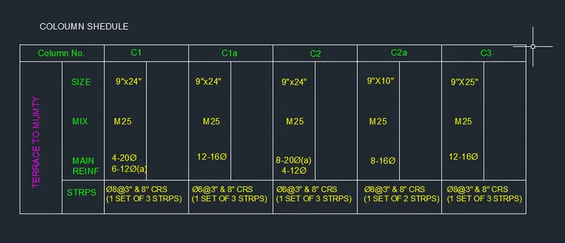
- Enter the text in the table by using singleline text from the text drop down menu - specify the point of text- specify text height as 8"
-Text agle as 0 degree, in case of the text TERRACE TO MUMTY" give text angle as 90 degreeand type the text. After entering the text,right click and slect properties - then list of properties will be displayed
- Ensure that the text height is 8" and make justify: as left
- To change the style of text Command "ST",a dialogue box apperas and select the font name as "romans.shx"
- Then insert all the text or copy the text created and edit it to the required text in respective rows and colums
- Give the heading as :"Column Shedule:"
II) Drawing the column section:
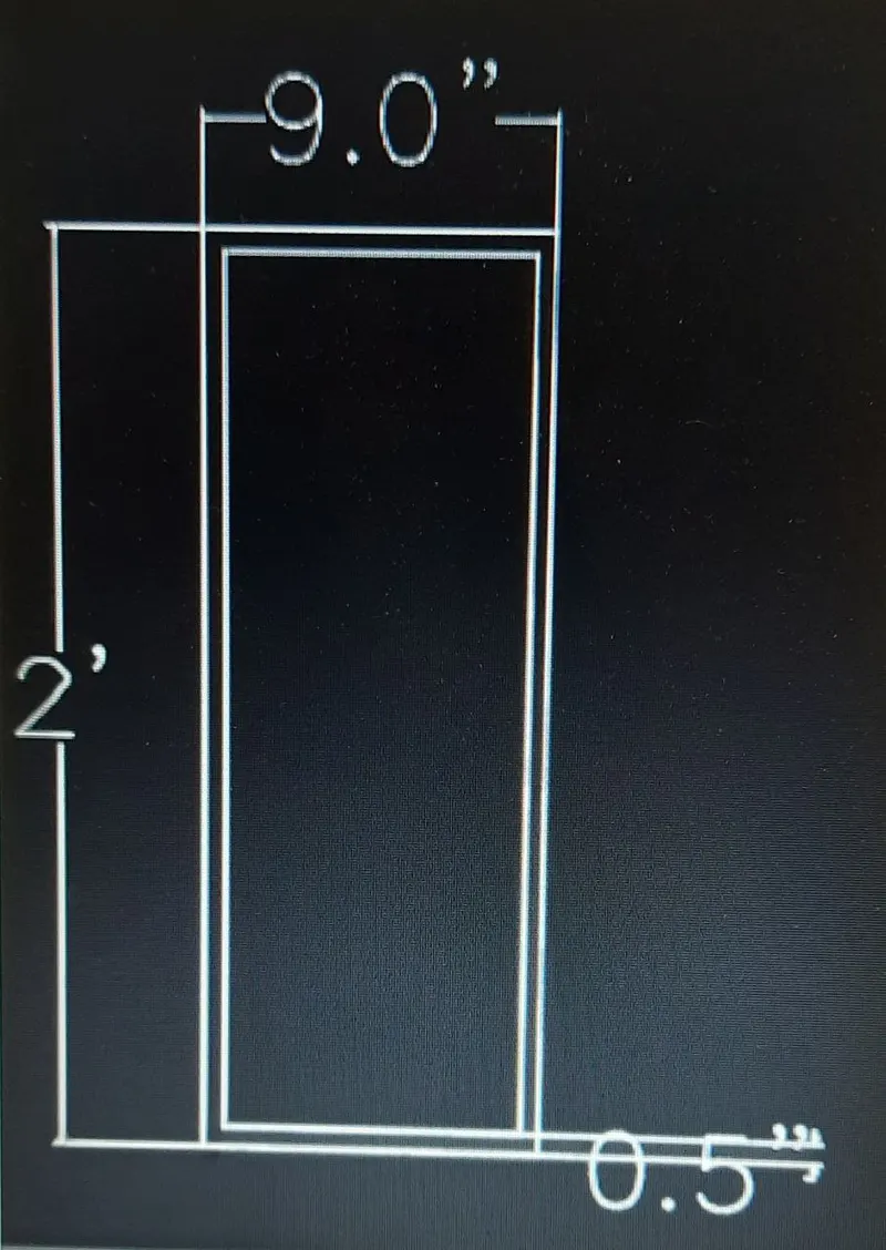
a) Drawing the column section C1 Column of size 9" x 24 having 20mm dia reinforcement at 4 corners and 12 mm dia 6 reinforcemnt bars in between connected by 8 mm dia stirrup.
Drawing column:
- Draw a rectangle of sixe 9 x24"- Command "REC"- specfiy a point- click on dimension in the command box- then enter the first value as 9 and second dimension as 24"
- Draw the column outline after a cover of 40mm ie ,0.5" by offset command Command "0"- select the object- give offset distance as 0.5" .
- Explode the inside rectangle so that the line can be selected seperately. Command "EXPLODE" - select the inner rectangle enter.
Drawing reinforcement:
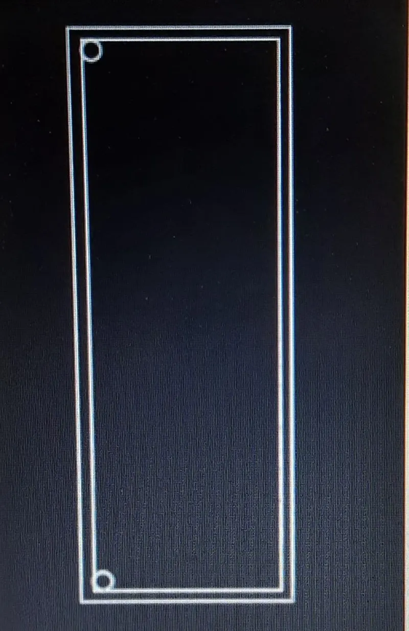
- By circle draw the reinforcement Command "C" - click on tan tan radius on the command box- select the left line as one of tangent - top line as another tangent give radius as 10mm ie,0. 4".
- Using mirror command create the reinforcement on bottom of the left side of column. Command "MI" - select the object- give the mirror plane as the midpoint of the 2 line by Object snap-midpoint on and click on "NO" for erase source object.
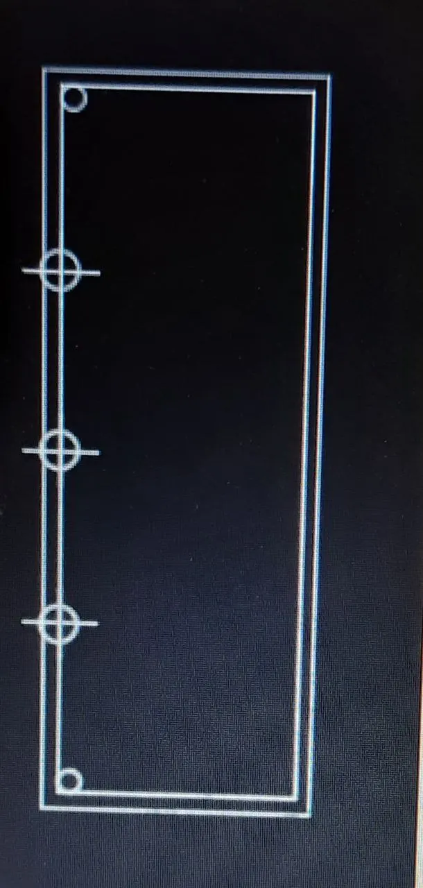
- Divide the line containing the reinforcement by command "DIV" - select the object (line)- no: of segments to be divided is given as 4,the line willbe divided
- To make the point of division visible, type Command "DDPTYPE" in command box - a dialogue box appears and select the suitable point type- apply.
- For the reinforcement of 12mm dia, 6 bars
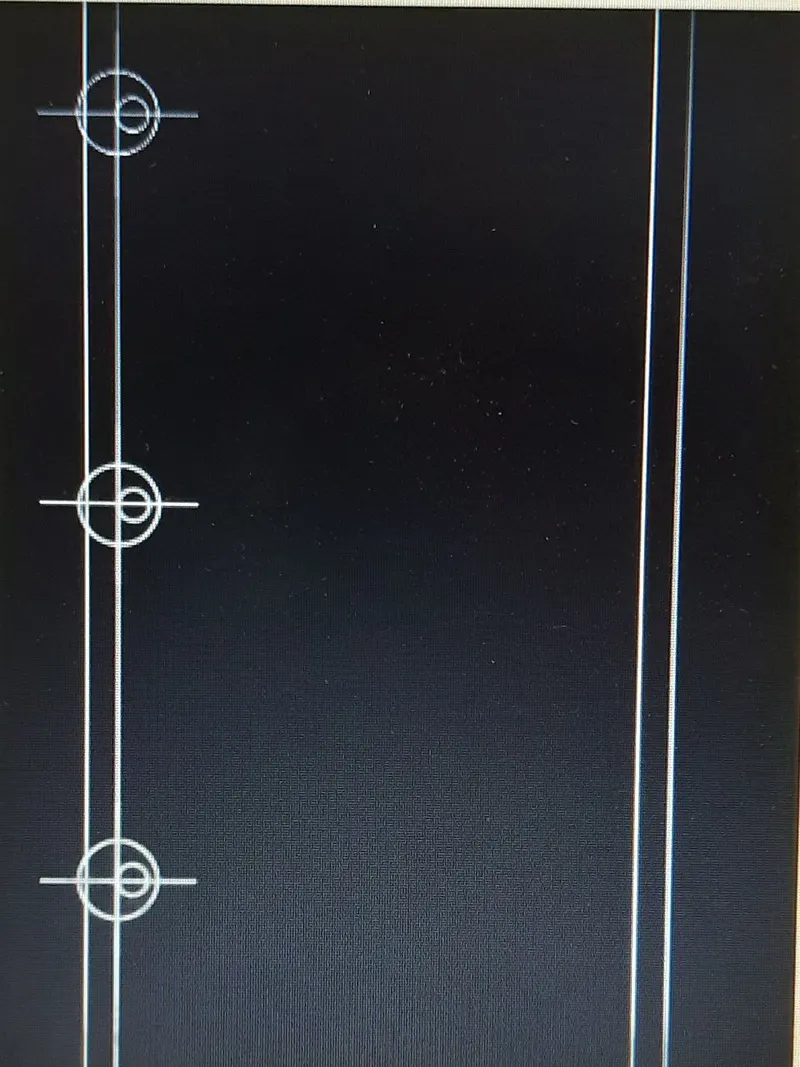
- Create circle by commnad "C"- specify the centre point - enter the radius as 6 mm ie 0.2".
- Copy the circle command "CO" - select the circle- select the base point as top point on the circle -and place it in the centre point of the point created by object snap on.
- Place 3 circles as such on each divided point, then dlete the points created.
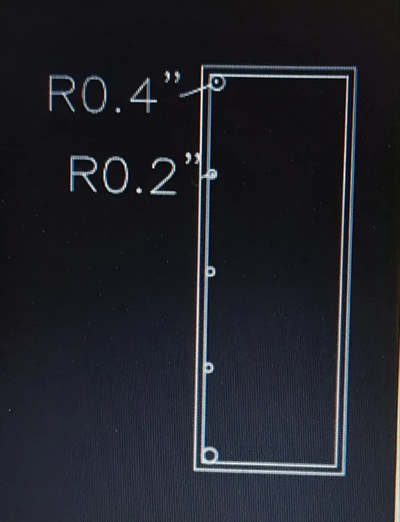
-Create similar circles on the other side, right side of the column. For that,
- Mirror the circles Command "MI"- select all the 5 circles- create the mirror plane from the middle of the 9" line ,erase source object -give it as "NO" then the mirror image will be created.

Drawing stirrups:
- Connect the reinforcement of raidus 6 mm,1st row from the top,2nd row top and bottom and 3rd row from bottom.
- Connect the lines as top tangent of the two circles.
- Draw the rings by arc- 3 point method, and mirroring it.
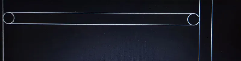
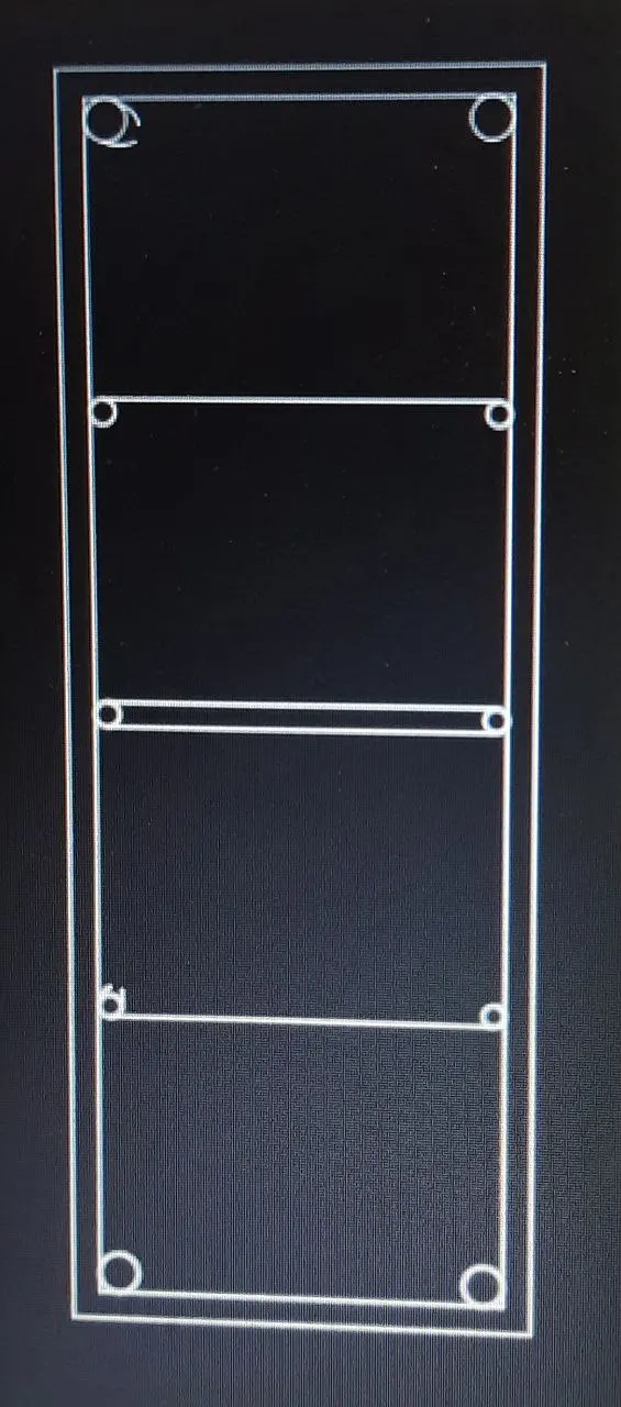
- Fillet the corners of the colum outline with filet radius as 0.5".
- Use donout command to fillthe circle Command "DO0"- specify the inner dimaeter as 0 and outer diameter as 0.8" for 4 corner reinforcement and 0.5" for inside reinforcement specify centre of the donout, it gets filled. Mark "a" for in between reinforcemnet to indicate it as 12mm dimaeter.
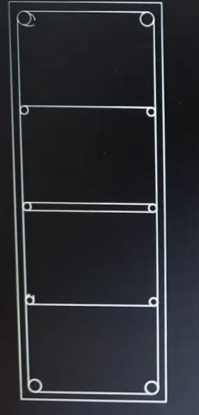
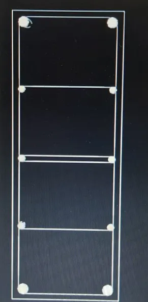
RESULT:
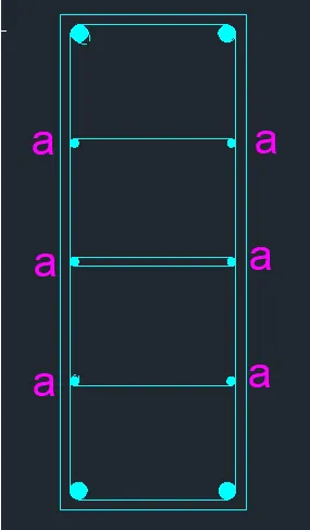
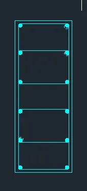
b) Drawing column section C1a- Column of size 9" x 24" having 16mm dia 12 bars connected by 8 mm dia stirrup.
Drawing column:
- Draw a rectangle of sixe 9'x24" - Command "REC" - specfiy a point- click on dimension in the command box - then enter the first value as 9" and second dimension as 24".
- Draw the column outline after a cover of 40mm ie ,0.5" by offset command Command "0"- select the object- give offset distance as 0.5".
- Explode the inside rectangle so that the line can be selected seperately. Command "EXPLODE" - select the inner rectangle enter.
Drawing reinforcement:
- By circle draw the reinforcement Command "C" - click on tan tan radius on the command box- select the left line as one of tangent - top line as another tangent give radius as 10mm ie,0. 4".
- Using mirror command create the reinforcement on bottom of the left side of column. Command "MI" - select the object- give the mirror plane as the midpoint of the 2 line by Object snap-midpoint on and click on "NO" for erase source object.
- Divide the line containing the reinforcement by command "DIV" - select the object (line)- no: of segments to be divided is given as 4,the line willbe divided
- To make the point of division visible, type Command "DDPTYPE" in command box - a dialogue box appears and select the suitable point type- apply.
- Copy the circle (reinforcement) and place it in the centre of the 4 points . as here all reinforcement are of same size.
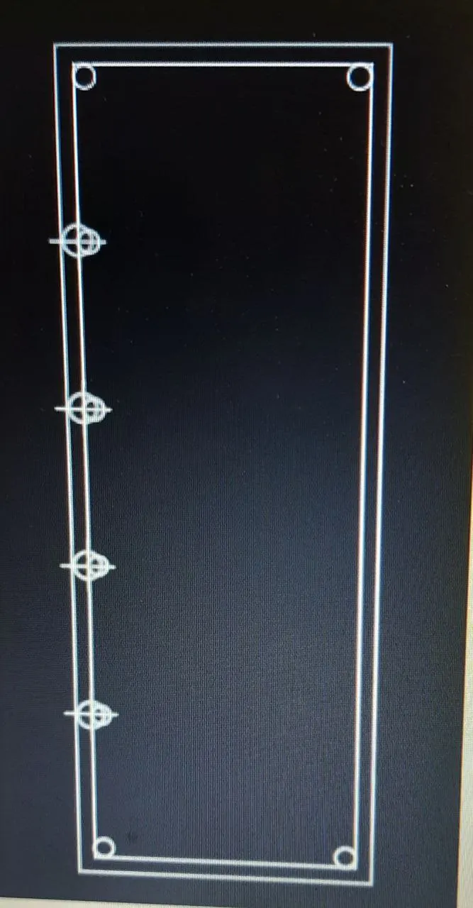
- Delete the points
- Mirror the circles to the right side by command "MI" - select all the 6 circles,then draw the mirror plane as the midpoint of the 9" line.and give erase source object as "NO".
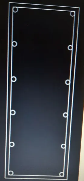
Drawing stirrups:
- With line command draw lines in top and bottom of reinforcements to show the stirrups same in the next set also.
- With arc -3 point methiod ,draw rings where required.
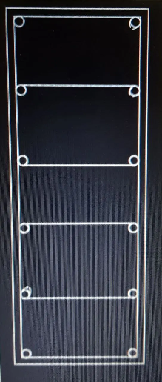
-Fillet the corners with fillet radius of 0.3".
- With "DO" command create donout -give inner dimaeter as 0 and outer diameter as 0.62"
RESULT:
c) Column C2 Column of sixe 9" x 24" having 20 mm dia 8 bars shown in figure as "a" and rest 12mm dia 4 bars with 8 mm dia stirrups
Drawing column:
-Draw a rectangle of sixe 9'x24"- Command "REC"- specIfiy a point - click on dimension in the command box - then enter the first value as 9" and second dimension as 24"
- Draw the column outline after a cover of 40mm ie ,0.5" by offset command Command "0"- select the object give offset distance as 0.5".
- Explode the inside rectangle so that the line can be selected seperately. Command "EXPLODE" - select the inner rectangle - enter.
Drawing reinforcement:
-With circle draw 20 mm reinforcement on left corner by tan -tan-radius method - select the circle and create mirror in bottom left corner .
- Divide the line by "DIV" command and divide it onto 5 segments 4 points are created
- Copy the reinforcemnt to the third and fourth row, Command: "CO". select the circle,and place it .
- Mirror the copied circles and the top and bottom circles to the right side Command "MI" - select the circles -then draw the mirror line towards the midpoint.
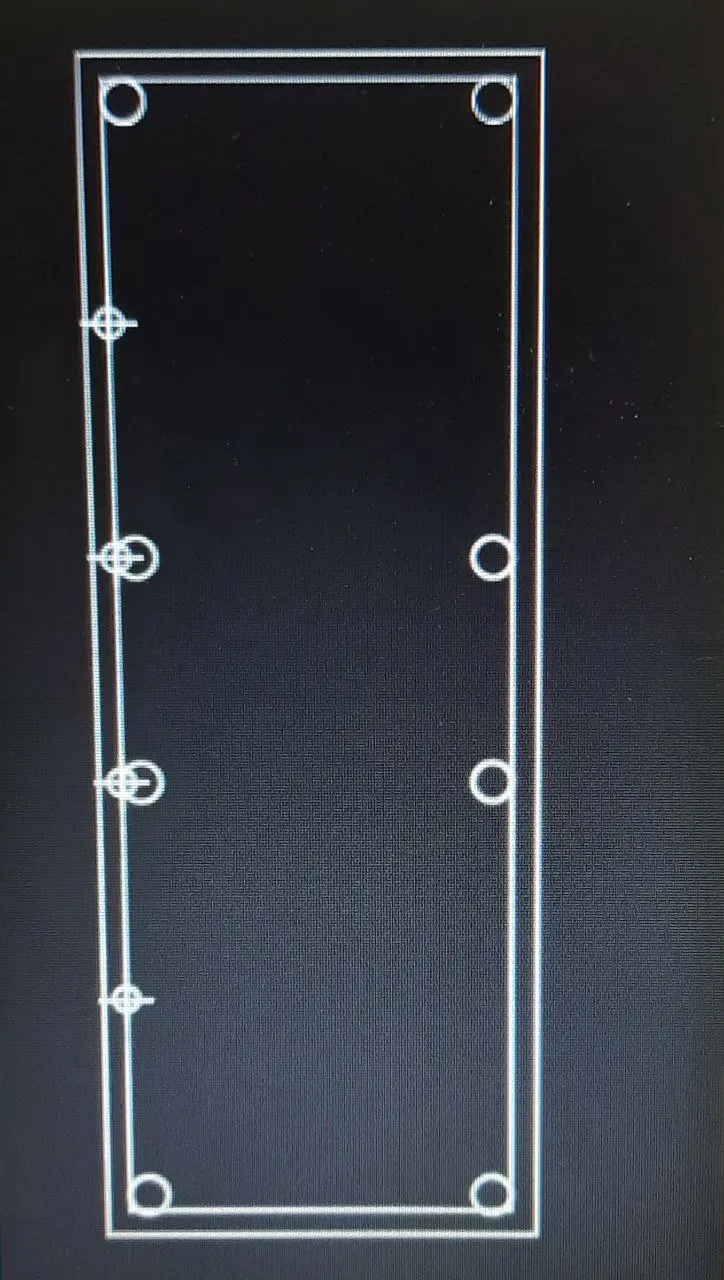
- Create circle of radius 0.23" and place it in the centre rest of the points created and mirror it as done in the previous step.

Drawing stirrups:
- By "L" line command draw lines connecting top and bottom of the reinforcement as in the figure
- Create rings by arc
- Fillet the corners of the column outline with fillet radius 0.4"
- Fill the circle by donout command "DO" - enter inner diameter as 0 and outer diameter as 0.7" and 0.4" respectively.
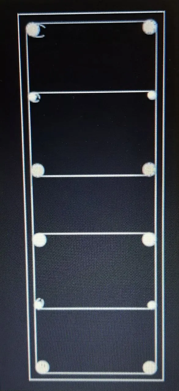
- Mark "a" with single line text on side of 20mm diameter reinforcement for identification.
Result:
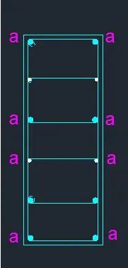
d) Drawing column C2a.
- Draw rectangle of 9" x10" and give offset of 0.5", explode the offseted rectangle.
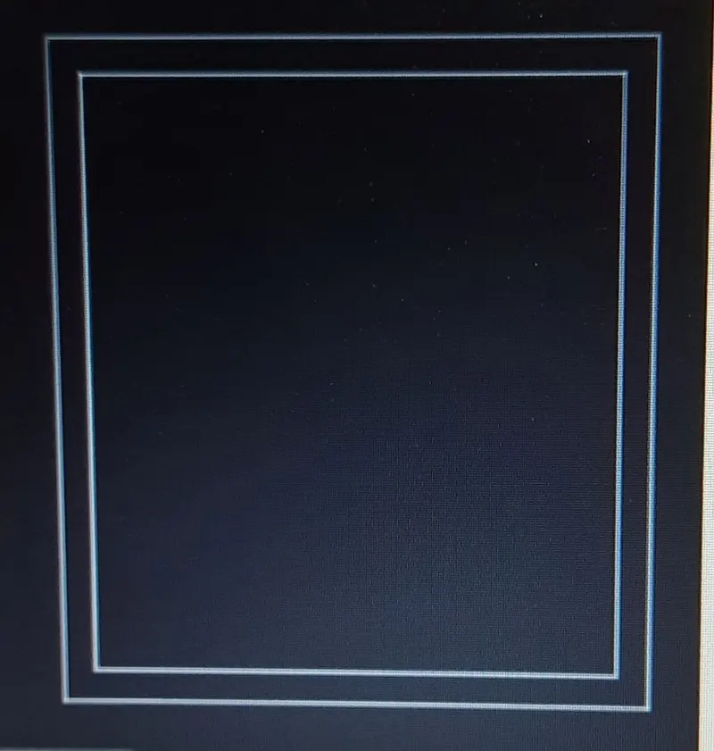
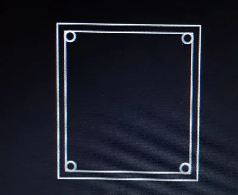
Drawing reinforcement:
- With circle command "C" - select tan tan radius - and select the two corner lines and give radius as 0.3". (8mm)
- Mirror these to the opposite coreners.
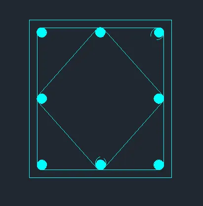
- Draw lines joining the midpoint of each side then by circle "C"- tan tan radius slect the two sides as tangent and give 0.3" as radius.
- Mirror the circles on opposite side by "MI" command.
- Again draw the other side reinforcement as done above.
- Create rings by arc -3 point
- Fill the reinforcement by donut command "DO" - give inner diameter as 0 and outer diameter as 0.6".
Result:
e) Drawing column c3 size 9" x21" reinforcement of 16mm dia 12 no's and stirrups od 8mm diameter.
Drawing column:
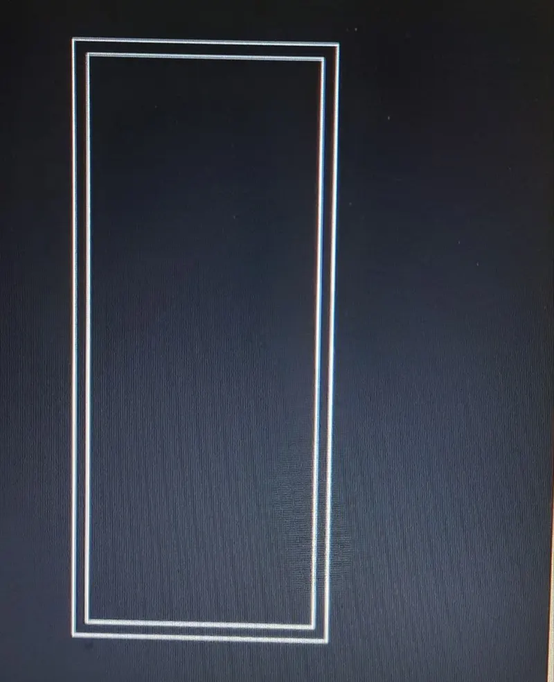
- Draw rectangle by command "REC" - click on dimension.give the dimensions as 9" and 21"
- Offset the rectangle with an offset distance of 0.5" by command "0" - distance as 0.5". Explode the inner rectangle.
Drawing reinforcement:
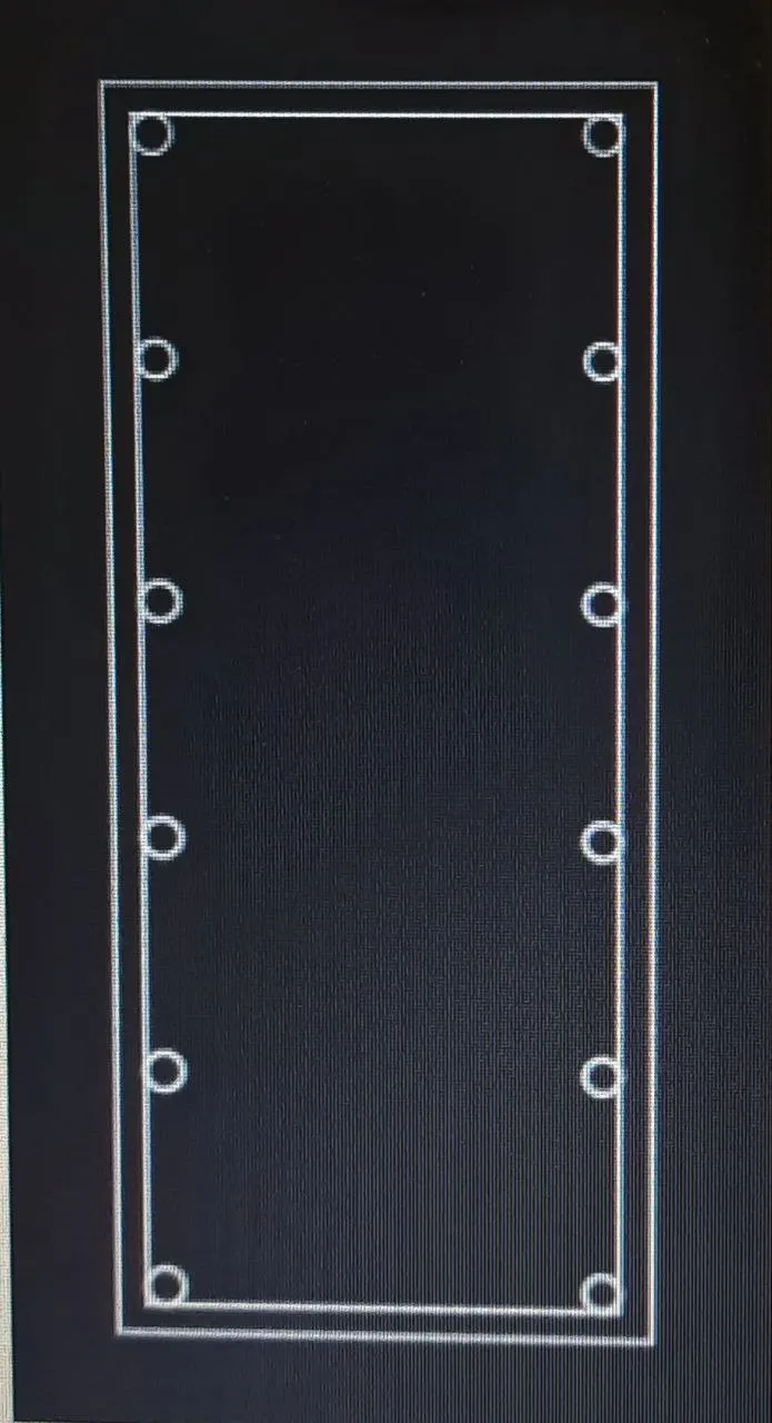
- By circle "C"- tan tan radius - select the two corner lines and give the radius as 0.3".
- Mirror the circle to the four corners of the column. Command "MI" - select the circle - draw the mirror plane at the midpoint of both the sides.
-Divide the line by "DIV" command into 5 segments, 4 points are created.
- Copy the circle and place it in the midpoint of the points by "C0" command.
-Mirror the copied circles on the other side command "M"- select the objects ,draw the mirror plane from the midpoint of the 9" line, give erase source object as "NO".
- Delete the points.
Drawing the stirrups:
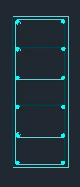
- With line command "L" draw the line from top and bottom of the reinforcemnt.
- Fillet the corners "F" - with fillet radius as 0.3".
- Create rings with arc 3 point
- Fill the reinforcement by donout command "D0" - give inner dia as 0 and outer dia as 0.6".
Result:
Placing it in column
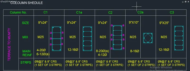
- Place each of the drawn columns in the respective table making it a scale of 4"
- Command "SC"- select the object - select base point- scale factor give it as 4".
Result: The column shedule is drawn:
2) CREATE A WINDOW SCHEDULE AS SHOWN IN THE FIGURES
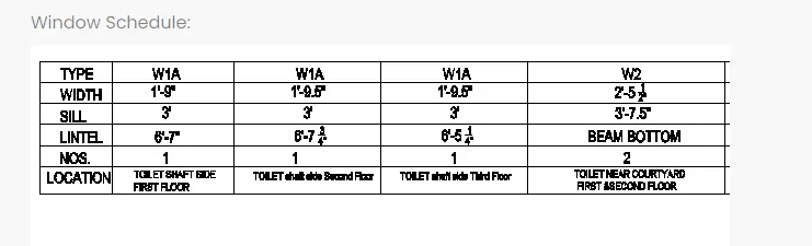
Aim: To draw the window shedule
Procedure:
- First the open the software
- Give the command QNEW and press the ENTERE key
- Click on imperical templete
- Select ADVANCE SETUP
- Unit : Engineering, precision :0.00
- Angle :decimal degree , precision :0.00
- Angle measure : East
- Angle direction : closkwise
- Area : 20*20
- And finished ,
- Command : D (dimension style manager )
- Click on :MODIFY
- Select : TEXT option
- Selct text style : romanc.shx
- Command : dt (for text )
- Lets start
Creating table:
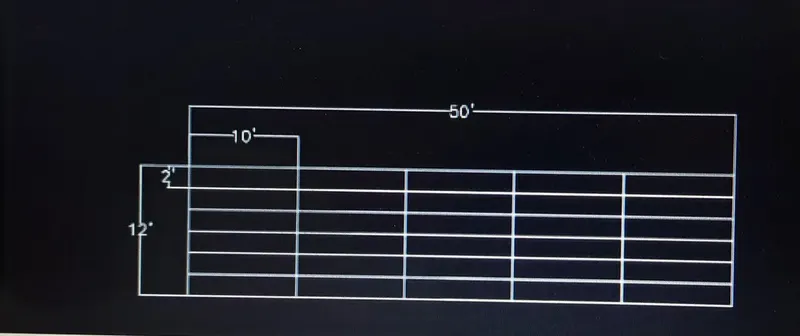
-By using line command draw a rectangle of length 50' and width 12'.
- Command "L" with ortho on 12' verticaly upwards then 50' towards + x direction,12' vertically downwards and close. Divide the length 50' into 5 equal parts ie 10' each
-Offset:command "O" and give the distance as 10' horizontaly to +x direction. Divide the 12' into 6 equal parts ie, 2' each. Command "O" and give the distance as 2' downwards
Inserting text:
- Select single line from the text drop down menu or type the command "DT" Specify start point of text specify the point where we need to start the text
- Specify text height- give it as 8"
- Specify rotation angle of text - give it as 0 degree (as we need the text in horizontal direction)
- Type the text we need to insert then press enter.
- If we need to change the style of text ,Command "ST" -
- Select the font ,here l have seleced "romans.shx"
- If we need to change the properties of text,select the text then right click -properties ,we can edit the properties we want.
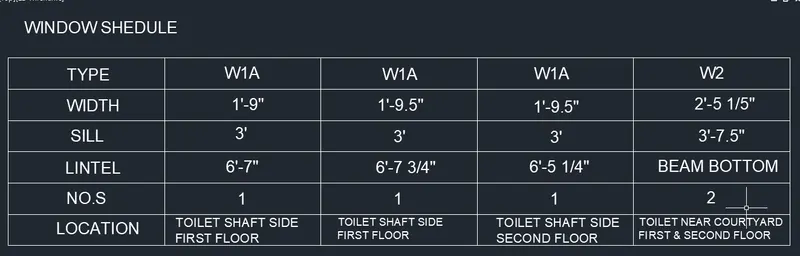
- Enter "TYPE", "WIDTH", "SILL", "NO",LOCATION" in the 1st column and "W1 A,W2 in the rows.
- We can copy the text and use the edit option to change the text by "CO" command.
- Enter the values given in the table, for fractional numbers enter the multiline text option.
- Select multiline from drop down menu of text, craete a rectangular box to type the text Type the number eg: in 1st row 2-5 1/2"
- In the location row text should be multiline and text size needs to be changed so,select the textright click- properties- text height- change it to 9" And last row text height is 7". Use grips to adjust the text box width and height to fit in the column.
Result: Window shedule is drawn:
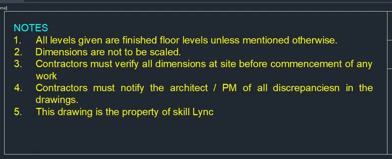
3) Create the drawing template as shown in the figure:< Use the Notes as in the figure>
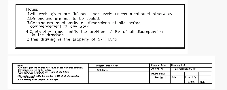
Aim: To create the template
Procedure:
- First the open the software
- Give the command QNEW and press the ENTERE key
- Click on imperical templete
- Select ADVANCE SETUP
- Unit : Engineering, precision :0.00
- Angle :decimal degree , precision :0.00
- Angle measure : East
- Angle direction : closkwise
- Area : 20*20
- And finished
- Command : D (dimension style manager )
- Click on :MODIFY
- Select : TEXT option
- Selct text style : romanc.shx
- Command : dt (for text )
- Lets start
Creating table:
- Create the left side of table by line command - Command "L"- draw line of 15' vertically upwards and 40' in +x direction,again 15' downwards,then close.
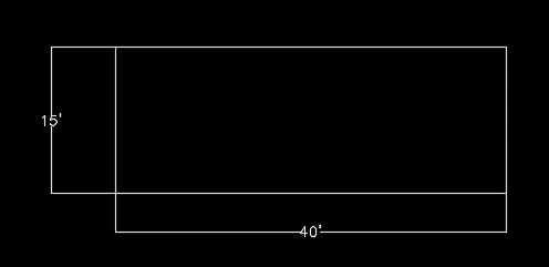
- Copy this rectangle and place it next to it with snap on, copy 2 of them.
- Command "Co" -select the object- select the base point - select the point where we need to place the rectangle.
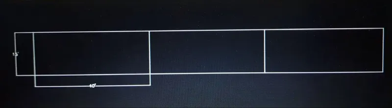
- Divide the 2nd column of table into two and the 3rd column into 5
- Command "0" -offset distance-3' seelct the object and create the rows.
- Also divide the 3rd column into 4 each of 10' by command "o" (offset)and trim the unwanted line by "TR" Command Table is created.
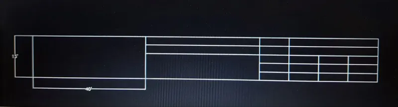
Inserting text:
- Select multi line from drop down list of text - create the text box, then type the data given Text height is given as 9".
Result: The template drawn is shown

4) Create the list of drawing schedule as shown in the figure.
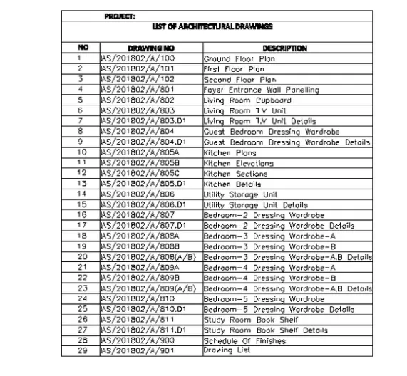
Aim: To create the list of drawings shedule
Procedure:
- First the open the software
- Give the command QNEW and press the ENTERE key
- Click on imperical templete
- Select ADVANCE SETUP
- Unit : Engineering, precision :0.00
- Angle :decimal degree , precision :0.00
- Angle measure : East
- Angle direction : closkwise
- Area : 20*20
- And finished
- Command : D (dimension style manager )
- Click on :MODIFY
- Select : TEXT option
- Selct text style : romanc.shx
- Command : dt (for text )
- Lets start
Creating table:
- With line tool draw the outline of the table of 102' x 83' with command "L"- specify the strat point, then draw 83 in + y direction -102' in +x direction 83' downwards and close.
- Draw the columns by offset command "O" with a distance of 10',32,60' respectively from the left side.
- Create the rows by offseting distance of 3',5' and 3' from the top side for the headings. Trim off the unwanted lines.
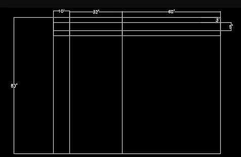
Insering heading texts:
- With multiline option from the text drop down menu ,create a text box in the 1st row and type" project" with text height 1-8" and style as romans .shx
- In the 2nd row,using multiline text type " LIST OF ARCHITECTURAL DRAWING" with text height of 2-1" and same style.
- In 3rd row type "NO: DRAWING NO:",DESCRIPTION" in respective columns with multiline text of height 1-8" and same style.
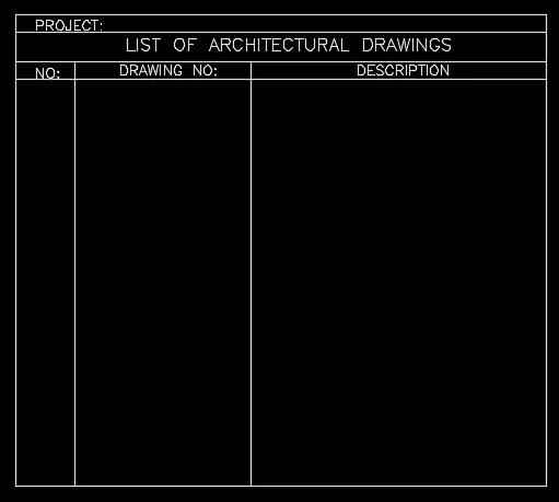
Creating the rows:
-With offset command'O" create rows of height 3',offset distance =3' ,create 24 such rows.
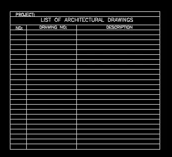
Inserting text:
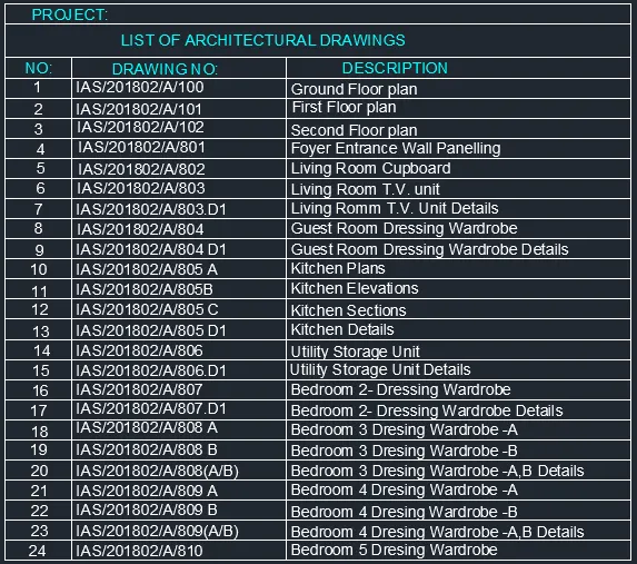
- Select multiline text and create the text box ,with text height 1-8" type the data given in each rows and columns.
-In the No: column, type the numbers from 1 to 24 In Drawing no: column type the first entity ,then copy Command"CO" - select the object- seelct "array" ,then enter the number of items in array as 23 ,then click on the point where we need to place the array
- select each text and edit it to the given text.
RESULT: The list of drawing shedule is created.
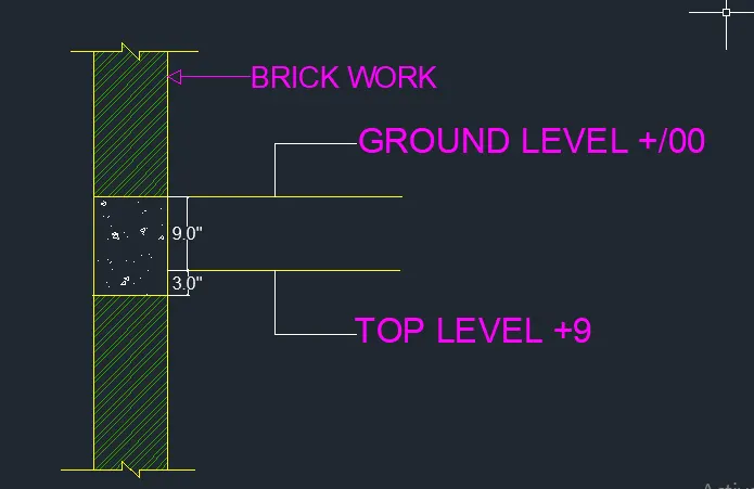
5) Create the Beam detail as shown in the figure and provide text wherever given.
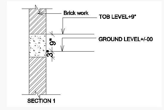
Aim: To draw the beam detail
Procedure:
- First the open the software
- Give the command QNEW and press the ENTERE key
- Click on imperical templete
- Select ADVANCE SETUP
- Unit : Engineering, precision :0.00
- Angle :decimal degree , precision :0.00
- Angle measure : East
- Angle direction : closkwise
- Area : 20*20
- And finished
- Command : D (dimension style manager )
- Click on :MODIFY
- Select : TEXT option
- Selct text style : romanc.shx
- Command : dt (for text )
- Lets start
- Draw cross-section of beam with height 4' and thickness 9" (wall thickness)
- With command "L", draw a line of 4' in + y direction an 9" in +x direction and 4' downwards and close.
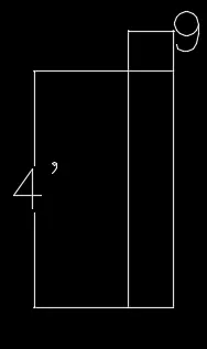
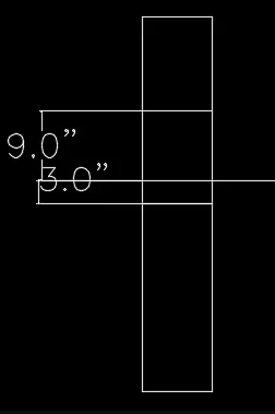
- From top give an offset of 9",which marks the ground level, Command "0" - select the top portion -give the offset distance as 9" and extend the grould level line.
- Then give an offset of 3" from 9" line Command "O" select the 9" line - give offset distance as 3" ,which indicate the bottom level of concrete.
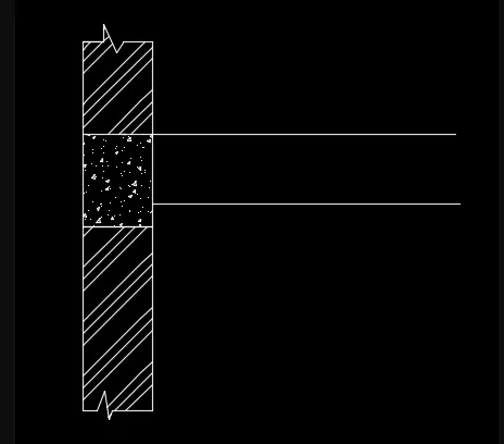
- Hatch the portion of brick and concrete and trim off the line of ground level from the cross-section of the beam.
Inserting text:
- Select multi learder from annotate tab and write the text with text height of 2"
- Type the text " TOP LEVEL +9" " at the top of 9" line,type "GROUND LEVEL +/00 " at the 3" ground line
- Type "BRICKWORK" indicating the part of brickwork using multileader. With multiline text from the text dropdown type "SECTION 1" at bottom of the figure at 2" height.
RESULT: The beam detail is drawn