Week 3 Challenge
- 1. State the primary load cases to be considered for design.
Answers :
- Dead load (IS 875 : PART 1 )
- Live load ( IS 875: PART 2)
- Wind load ( IS 875 : PART 3)
- Snow load ( IS 875 : PART 4)
- Seismic load (IS 1893 : 2016)
- What is One – Way slab?
Answers :
- One way slab is the slab in which the ratio of it’s longer span to the shorter span is more than equal to 2
- The load distribution in a one way -slab takes place along it’s shorter span
- Consequently , the bending also happens along the shorter span of the one -way slab
- As a result , one way slabs are generally rested over only two beams as opposed to the two way slabs that are rested over four beams along their periphery
- What is the value of unit weight of structural steel and soil?
Answers :
- Structural Stee -78 KN /m^3
- Soil - 18 KN / m^3
- Name few sections that can be defined using Properties tab in STAAD Pro.
Answers :
- Circle
- Rectangular
- T- sections
- I -sections
- Trapezoidal
- Tapered -I
- Custom Geometric Sections
- Define Primary Beams.
Answers :
- Primary beams are then ones that are connected with columns on both ends .
- Primary beams are supposed to transfer loads of slabs directly to the column they are resting on .
- 1. State the factors and parameters that influence the design pressure intensity of a high-rise building.
Answers :
Below are the factors governing design pressure intensity of a high -rise building
Design wind speed is given by following formula
Vz = Vb x K1 x K2 x K3 x K4
Here ,
Vb - Basic wind speed based on where the project is located within India
K1 - Risk coefficient factor based on the basic wind speed of the location (Table 1-IS 875 PART 3)
K2 -Terrain and height factor
K3 -Topography factor
K4 -Importance factor for cyclonic regions
Then finally , the design wind pressure (Pz) is given by :
Pz = 0.6 X (vz)^2
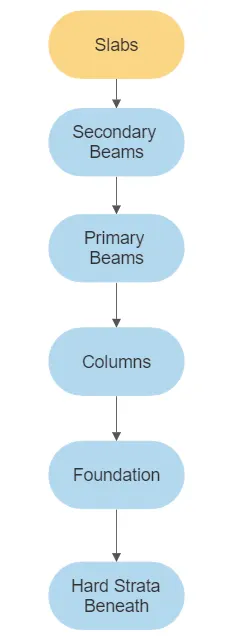
- Mention the load transfer process of a Reinforced Concrete Building.
ANSWERS :
- 1. Differentiate One-Way and Two way slabs. Elaborate each slab type.
Answers :
|
One - way Slab |
Two - way Slab |
|
L/B ratio is more than or equal 2 |
L/B ratio is less than 2. |
|
Bending takes place only in one direction that is along the shorter span |
Bending takes place along both spans |
|
One -way slabs are supported by beam in only two directions |
Two -way slabs are supported by beams on all four sides |
|
Main steel is only provided in one direction that is along the direction of bending |
Main steel is provided in both directions which are X and Y |
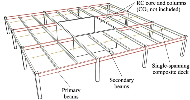
- Explain the concept of secondary beams with proper sketch.
Answers :
secondary beams :
- Secondary beams are provided for better distribution of various slab loads along the primary beams on which the slabs rests
- These are beams that not directly connected to the columns and rather rest on other beams that are directly resting on columns also known as the primary beams .
- Secondary beams are supposed to carry a certain amount of the total load and help distribute the same in improved fashion . also
- It is important to release end moment at support for secondary beams and for the same purpose , all the secondary beams are provided with pinned connections .
3.Mention the Primary load cases.
A.State the Indian Standards for each load case
B.Detail the parameters of each load case
C.Brief each load case
Answers :
Dead load (IS 875 : PART 1 ) :
- Dead loads are the gravity loads generated due to the self weight of the structure .
- The name of the dead loads are static and do not change throughout the service period of the structure .
- As we know , all the structural elements such as slabs ,beams and columns are heavy and process a significant amount of load that needs to be accounted for .
- Hence part one of the IS 875 specifically deals with the density of structural material using which we can obtain the dead load caused based on the size of the section
Live load ( IS 875: PART 2) :
- Live loads are load that not constant and may be vary during the functioning of building
- Live loads are different for different types of structure . for example , the live load for industrial building with heavy machinery is certainly going to be more than that of a residential structure
- Similarly it also various types of room occupancy .
- Therefore the part of IS 875 provides us with guidance on how to consider live loads for different structures and different part of the same building .
- Accordingly ,the live loads for all rooms, bathrooms , and kitchens is taken as 2kn/m^2 .
- On the other hand , it is taken as 3kn/m^2 for stairs and hall areas where people are supposed to gather .
Wind load ( IS 875 : PART 3) :
- Wind load is also an important load causes that is dealt with part three of the indian standard 875 . the formula and all the governing factors are briefly explained in this code so as to obtain the total design wind pressure .
Snow load ( IS 875 : PART 4) :
- Snow load is governing loas cases for structures that are located in the mountain and hilly area that encounter regular snow rains.
- The loads are generally calculated for the building roof
Earthquake load ( IS 1893 -2016) :
- Earthquake loads or seismic loads are also primary type of loads case considered for design and analysis of high - rise buildings .
- And as per the codel provisions , the dynamic seismic analysis can be conducted via any one the two methods namely response spectrum analysis and time history analysis .
- Detail the steps involved in assigning Properties and Support to a model using STAAD Pro sequentially.
ANSWERS :
Open “STAAD.Pro software” > Click “NEW” > Give Name of the drawing > Select “MATRIC” option > Click “CREATE” > u will get New window > Go to “PROPERTIES” > u will get dialog box called “Properties -Whole Structure” > Click “DEFINE” > u will get another dialog box called “Property” > choose the desired selection from the list is it Circle , Rectangalure , Trapezoidal , T -section etc. > specify the section dimensions in the dialog box . > click “ADD” and “CLOSE” > Now to assign , select the same section from the created section list and check the ratio button > “assign selected to view “ > click “ASSIGN” >
Similarly to assign end conditions , Go to “Support “ > create “NEW” > Specify fixed pinned or other > click on “add” > select the “ADDED and “ASSIGN “ it to “VIEW”
- Brief the steps to be followed to create and assign secondary beams in STAAD Pro
Answers :
- Open “STAAD.Pro software”
- Click “NEW”
- Give Name of the drawing
- Select “MATRIC” option
- Click “CREATE”
- u will get New window > right click “STAAD SCREEN”
- Go to “NODE”
- let me create “Origin”
- right click the mouse
- Go to “Select Cursor”
- Select “NODE Cursor”
- Select the “Nodes” in the screen
- Click “Ctrl+C” and “Ctrl+V”
- U will get dialog box called “PAST WITH MOVE”
- Give a “Y” as in “METRE” ex: 3m
- Click “OK”
- Now select all the”NODES” in screen
- Click “CTRL+C” and “CTRL+V”
- Again u will get dialog box called “PAST WITH MOVE “
- Now give a “Z” as in “METRE” , ex: 8m
- Click “OK”
- Now u will get “8 Nodes” in the screen.
- Go to “ADD BEAM” option
- Connect the ”BEAM” to all the “NODES”
- Go to “PROPERTIES”
- Click “DEFINE”
- U will get dialog box called “Property”
- Select “RECTANGULAR” option
- Give a value in “YD” and “ZD” in “Metre”
- Click “ADD” and “CLOSE”
- Than click “ASSIGN TO VIEW” option
- Click “ASSIGN”
- Than click “YES”
- Go to “MATERIALS”
- Select “CONCRETE”
- Than click “ASSIGN TO VIEW” option
- Click “ASSIGN”
- Than click “YES”
- Go to “SUPPORTS”
- Click “CREATE “ option
- U will get dialog box called “CREATE SUPPORT”
- Go to “FIXED” option
- Click “ADD” option
- Select the “BEAM”
- Then “ Right click “
- Go to “Insert Node”
- Then u will get dialog box called “INSERT NODES IN TO THE BEAM “ option
- Click “ADD MID POINT” option
- Click “OK”
- Go to “ADD BEAM” option
- Click “PERPENDICULAR INTERSECTION” option
- Then create beam mid of node
- Go to “PROPERTIES”
- U will get dialog box called “Property”
- Select “RECTANGULAR” option
- Give a value in “YD” and “ZD” in “Metre”
- Click “ADD” and “CLOSE”
- Than click “ASSIGN TO VIEW” option
- Click “ASSIGN”
- Than click “YES”
- Go to “MATERIALS”
- Select “CONCRETE”
- Than click “ASSIGN TO VIEW” option
- Click “ASSIGN”
- Than click “YES”
- Go to “LOADING” option
- Go to “LOAD CAUSES DETAILS “
- U will get dialog box called “NEW LOAD CAUSES”
- Select “DEAD LOAD”
- Give a title as “DEAD LOAD “
- Click “ADD”
- Select “LIVE LOAD”
- Give a title as “LIVE LOAD “
- Click “ADD”
- Select “DEAD LOAD “
- Click “ADD” option
- Let assign “SELF WEIGHT”
- Select “LIVE LOAD “
- Click “ADD” option
- Let assign “MEMBER LOAD ”
- Give a weight as KN/m , EX : -3
- Click “ADD” and “CLOSE”
- Select “SELF WEIGHT”
- Click “ASSIGN”
- Click “YES”
- Go to “SELECT “ option
- Let me select “PARALLEL TO X “ and “PARALLEL TO Y”
- Then click “SELECTED OBJECT” option
- Same as “MEMBERS LOAD”
- Click “ASSIGN”
- Click “YES”
- Right click the mouse
- Go to “LABELS”
- Go to “SCALES”
- Give a “DIST FORACE “ as “15 KN/m Per m”
- Then click “DISPLAY WHOLE STRUCTURE”
- Go to “ANALYSIS” option
- Click “ANALYSIS COMMANDS”
- Click “PERFORM ANALYSIS”
- Click “ADD” and “CLOSE”
- Click “RUN ANALYSIS” option
- U will get dialog box called “STAAD Analysis and design”
- Select “GO TO POST PROCESSING MODE”
- Click “DONE” option
- U will get another dialog box called “RESULT SETUP”
- Select “DEAD LOAD “ and “LIVE LOAD”
- Click “APPLY” and “OK”
- Go to “BEAM RESULT “ and “MOMENT”
- Click “ANNOTATE” option
- Go to “BEAM RESULTS”
- U will get dialog box called “ANNOTATE -SECONDARY BEAM -WHOLE STRUCTURE”
- Select bending as”ENDS” and “MEDIUM”
- Click “ANNOTATE”
- Then right click
- Go to “LABELS”
- Go to “SCALES”
- Give a “BENDING MOMENT”
- Click “APPLY” and “OK”
Practical
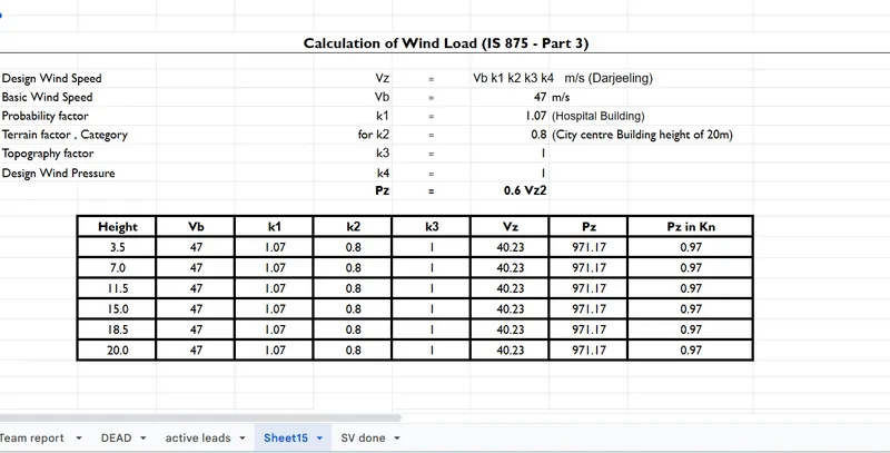
- Calculate the wind pressure for the given building
- Building Dimension : 20m x 30m x 20m height RCC
- Building usage : Hospital block in city centre
- Location : Darjeeling
ANSWERS :
- Calculate the Dead load and Live load for the above building with reference to IS standards ( assume suitable sections )
ANSWERS :
Dead Load due to Slabs :
Assuming 200mm thick slabs ,
Dead load due to to one slab = 20 X 30 X 25 X 0.20 = 300 Kn
Now , as there are total of five slabs in the building
Total dead load due to all the slabs = 300 x 5 = 1500 kn
Dead load due to the Beams
Considering the beams of cross -section 350 x 450mm
Dead load due to beams = 0.35 x 0.45 x 25 = 3.94 kn/m
Rounding off above value , we get.
Superimposed loads due to the partition wall :
Assuming 150 mm thick Brick work
Height of the brick work = Floor Height - beam depth = 3.75-0.45 =3.3 metres.
Therefore ,
Dead load due to the brick masonry partition = 3.3x 0.15x 18 =8.91 kn/m
Live load :
As the proposed project a hospital building , The IS 875 PART 3 states different live load values for different rooms within a hospital that are listed below .
|
OCCUPANCY |
LIVE LOAD |
|
For ward rooms , dressing room , dormitories and lounges |
2.0Kn/m^2 |
|
Kitchen and laboratory |
3.0Kn/m^2 |
|
Dinning room ,cafeteria |
3.0Kn/m^2 |
|
Toilets and bathrooms |
2.0Kn/m^2 |
|
X-RAY room and operating theatre |
3.0Kn/m^2 |
|
Office and OPD room |
2.5Kn/m^2 |
|
Corridor , passages |
4.0Kn/m^2 |