Creation of geometries by Coordinate system methods using AutoCad
Aim :
Creation of geometries by Coordinate system methods using AutoCAD
- There are four AutoCAD coordinate system :-
- Absolute coordinate system
- Relative rectangular coordinate system
- Relative polar coordinate system
- Direct distance entry system
Absolute coordinate system :-
- In absolute coordinate system , all input points specify in drawing are with respect origin (0,0)
Relative rectangular coordinate system:-
- In relative rectangular coordinate system , first point is entered with respect origin (0,0) and all the next points can be entered by specifying next coordinate with respect to the first point
- The relative coordinate started with symbol “@” . In relative rectangular coordinate system , points entered by typing “@ x,y “ and press Enter
Relative Polar coordinates system :-
Polar coordinates used when we need to draw the next points at a specify angel.
Polar coordinates system in AutoCAD specifies distance length at an angle.
In Relative polar coordinate system , points entered by typing “ @ distance
Direct Distance Entry:-
It is simple method of drawing .
Direct distance entry enable to draw an object by pointing in particular direction with cursor and entering a distance at the commend box .
Aim : create the geometry of given picture in AutoCAD using all the coordinates system methods .
Procedure :-
Step 1: on opening the autocad software , step the units imperial template and decimal system to 0.000.
Step 2: set the limits in commercial tab using “ LIM ‘’ before drafting.
Now,
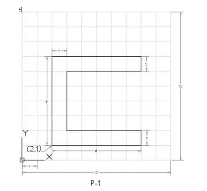
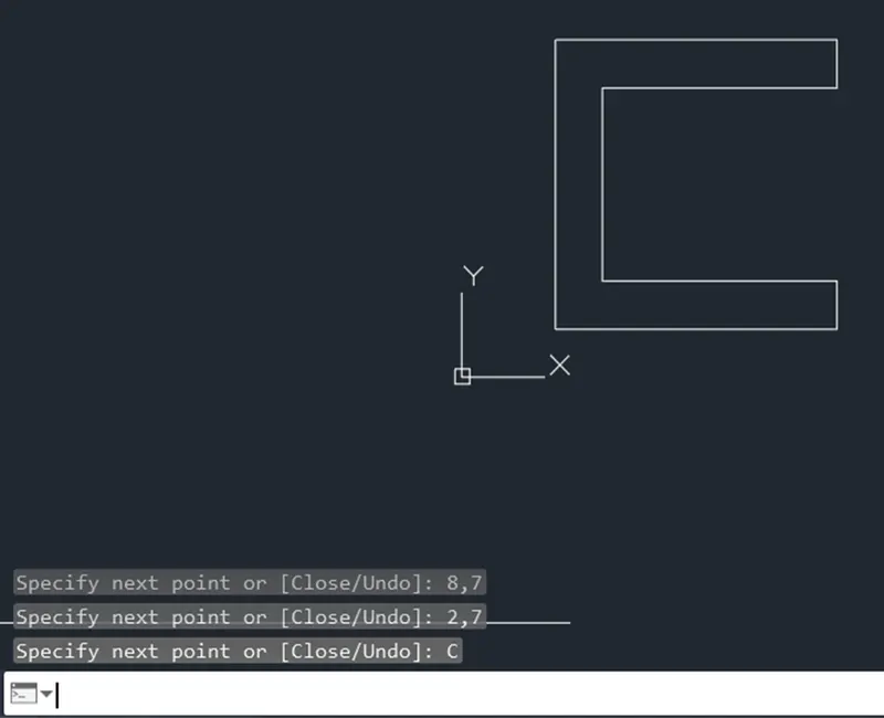
Step of creating geometry in AutoCAD software by Absolute coordinate system :-
- Type the command “L” for the line and specify the coordinate for starting points 1 (2,1)
- Type the next coordinate of point 2 (8,1) in the command box .
- Type the next coordinate of point 3 (8,2) in the command box .
- Type the next coordinate of point 4 (3,2) in the command box .
- Type the next coordinate of point 5 (3,6) in the command box .
- Type the next coordinate of point 6 (8,6) in the command box .
- Type the next coordinate of point 7 (8,7) in the command box .
- Type the next coordinate of point 8 (2,7) in the command box .
- Click “close” on the command box
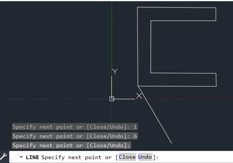
Result :-
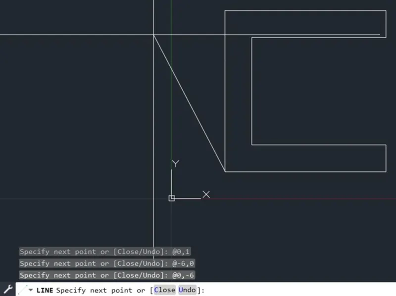
Step of creating in AutoCAD software by Relative Rectangular coordinate system :-
- Type the command “L” for the line and specify the coordinate for starting points 1 (2,1)
- Type the next coordinate of point 2 @6,0 in the command box .
- Type the next coordinate of point 3 @0,1 in the command box .
- Type the next coordinate of point 4 @-5,0 in the command box .
- Type the next coordinate of point 5 @0.4 in the command box .
- Type the next coordinate of point 6 @5,0 in the command box .
- Type the next coordinate of point 7 @0,1 in the command box .
- Type the next coordinate of point 8 @-6, 0 in the command box .
- Click “close” on the command box
Result :-
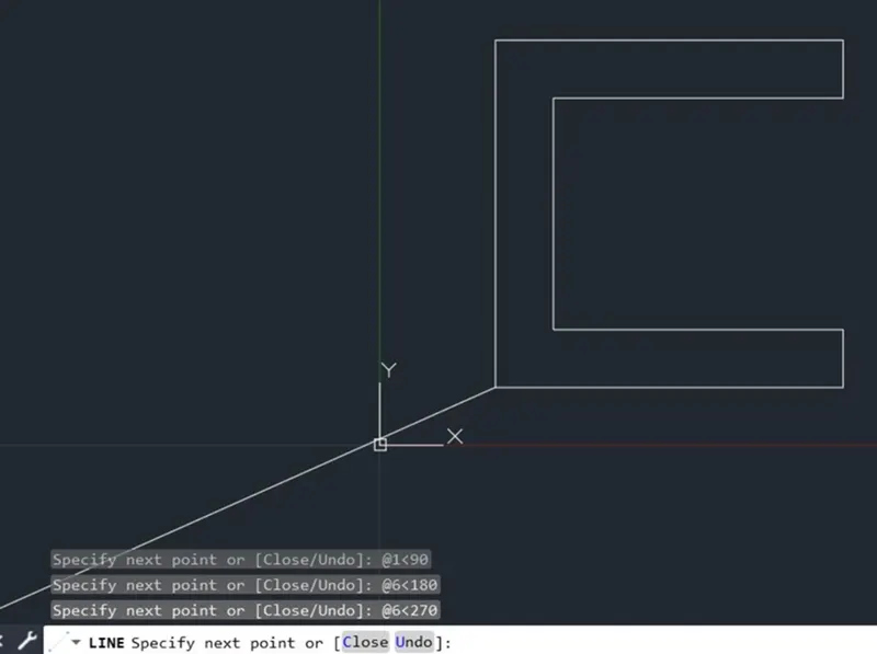
Steps of creating geometry in AutoCAD software by Relative polar coordinate :-
- Type the command “L” for the line and specify the coordinate for starting points 1 (2,1)
- Type the next coordinate of point 2 @6<0 in the command box .
- Type the next coordinate of point 3 @1<90 in the command box .
- Type the next coordinate of point 4 @5<180 in the command box .
- Type the next coordinate of point 5 @4<90 in the command box .
- Type the next coordinate of point 6 @5<0 in the command box .
- Type the next coordinate of point 7 @0<90in the command box .
- Type the next coordinate of point 8 @6<180 in the command box .
- Click “close” on the command box
Result :-
Steps to create geometry in AutoCAD software by Direct Distance Entry:-
- Type the command “L” for the line and specify the coordinate for starting points 1 (2,1)
- Type the length 6 in command box to +ve x- axis for point 2.
- Type the length 1 in command box to +ve y- axis for point 3.
- Type the length 5 in command box to -ve x- axis for point 4.
- Type the length 4 in command box to +ve y- axis for point 5.
- Type the length 5 in command box to +ve x- axis for point 6.
- Type the length 1 in command box to +ve y- axis for point 7.
- Type the length 6 in command box to -ve x- axis for point 8.
- Click “ Close” on the command box
Result :-
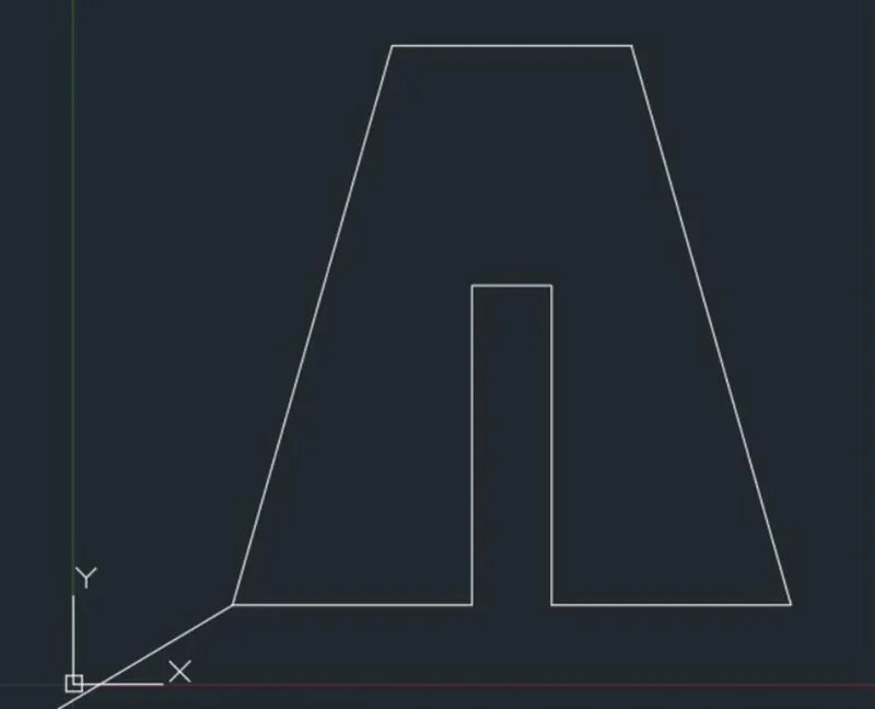
Aim: create the geometry of the given picture in AutoCAD using all the coordinate system method.
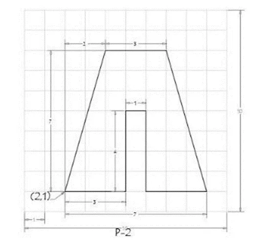
Procedure :-
Step 1: on opening the AutoCAD software , step the units imperial template and decimal system to 0.000.
Step 2: set the limits in commercial tab using “ LIM ‘’ before drafting.
Now,
Step of creating geometry in AutoCAD software by Absolute coordinate system :-
- Type the command “L” for the line and specify the coordinate for starting points 1 (2,1)
- Type the next coordinate of point 2 (5,1) in the command box .
- Type the next coordinate of point 3 (5,5) in the command box .
- Type the next coordinate of point 4 (6,5) in the command box .
- Type the next coordinate of point 5 (6,1) in the command box .
- Type the next coordinate of point 6 (9,1) in the command box .
- Type the next coordinate of point 7 (7,8) in the command box .
- Type the next coordinate of point 8 (4,8) in the command box .
Click “close” on the command box
Result:-
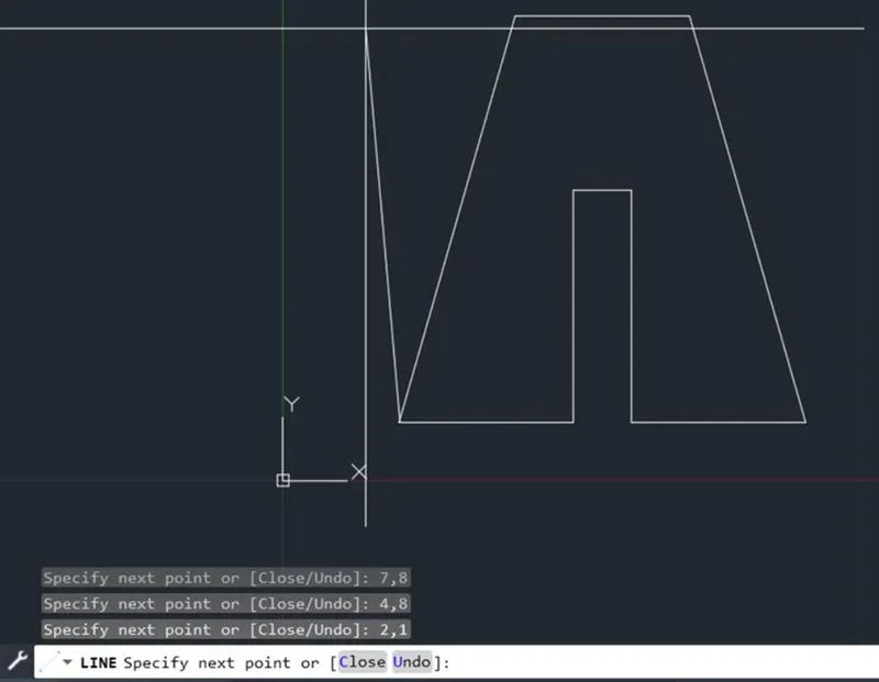
Step of creating in AutoCAD software by Relative Rectangular coordinate system :-
- Type the command “L” for the line and specify the coordinate for starting points 1 (2,1)
- Type the next coordinate of point 2 @3,0 in the command box .
- Type the next coordinate of point 3 @0,4 in the command box .
- Type the next coordinate of point 4 @1,0 in the command box .
- Type the next coordinate of point 5 @0,-4 in the command box .
- Type the next coordinate of point 6 @3,0 in the command box .
- Type the next coordinate of point 7 @-2,7 in the command box .
- Type the next coordinate of point 8 @-3 ,0 in the command box .
- Click “close” on the command box
Result :-
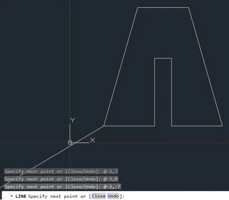
Steps of creating geometry in AutoCAD software by Relative polar coordinate :-
- Type the command “L” for the line and specify the coordinate for starting points 1 (2,1)
- Type the next coordinate of point 2 @3<0 in the command box .
- Type the next coordinate of point 3 @4<90 in the command box .
- Type the next coordinate of point 4 @1<0 in the command box .
- Type the next coordinate of point 5 @4<270 in the command box .
- Type the next coordinate of point 6 @3<0 in the command box .
- Type the next coordinate of point 7 @7<90in the command box .
- Type the next coordinate of point 7 @2<180 in the command box and then cancel the line command by pressing Enter.
- Now use line command “L” specify the point 7 and then cancel the line command by pressing enter.
And delete lines joining from point 6 to 9 and point 9to 7
- Type the command “L” specify the point 7 (7,8) and type the next coordinate of point 8 @3< 180 in the command box and then cancel the line command by pressing enter.
- Now use line command “L” and join point 8 and point 1 and then cancel the line command by pressing enter
Result :-
Steps of creating geometry in AutoCAD software by Direct Distance Entry :-
- Type the command “L” for the line and specify the coordinate for starting points 1 (2,1)
- Type the length 3 in command box to +ve x- axis for point 2.
- Type the length 4 in command box to +ve y- axis for point 3.
- Type the length 1 in command box to +ve x- axis for point 4.
- Type the length 4 in command box to -ve y- axis for point 5.
- Type the length 3 in command box to +ve x- axis for point 6.
- Type the length 7 in command box to +ve y- axis for point 9.
- Type the length 2 in command box to -ve x- axis for point 7 and then cancel the line command by pressing enter.
- Now use line command “L” and join point 6 and 7 and then cancel line command by pressing enter.
And delete lines joining from point 6 to 9 and point 9 to 7
- Type the command “L” specify the point 7 (7,8) and type the next coordinate 8 @ 3<180 in the command box and then cancel the line command by pressing enter.
- Now use line command “L” and join point 8 and point 1 and then cancel the line command by pressing enter
Result :-
Aim : create the geometry of given picture in AutoCAD using all the coordinate system methods.
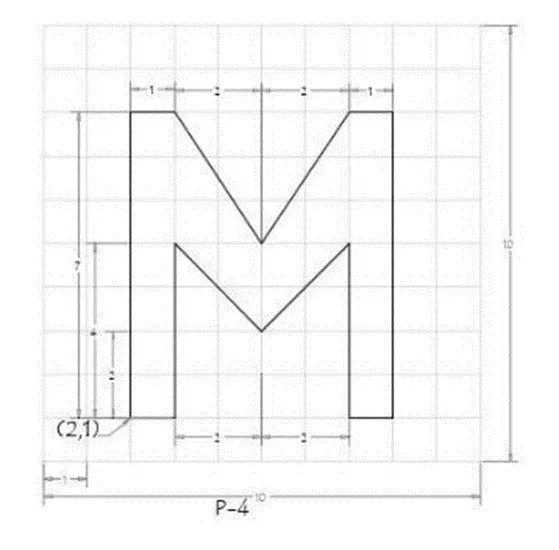
Procedure :-
Step 1: on opening the autocad software , step the units imperial template and decimal system to 0.000.
Step 2: set the limits in commercial tab using “ LIM ‘’ before drafting.
Now,
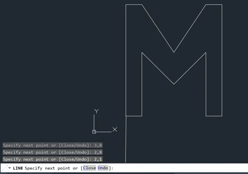
Step of creating geometry in AutoCAD software by Absolute coordinate system :-
- Type the command “L” for the line and specify the coordinate for starting points 1 (2,1)
- Type the next coordinate of point 2 (3,1) in the command box .
- Type the next coordinate of point 3 (3,5) in the command box .
- Type the next coordinate of point 4 (5,3) in the command box .
- Type the next coordinate of point 5 (7,5) in the command box .
- Type the next coordinate of point 6 (7,1) in the command box .
- Type the next coordinate of point 7 (8,1) in the command box .
- Type the next coordinate of point 8 (8,8) in the command box .
- Type the next coordinate of point 5 (7,8) in the command box .
- Type the next coordinate of point 6 (5,5) in the command box .
- Type the next coordinate of point 7 (3,8) in the command box .
- Type the next coordinate of point 8 (2,8) in the command box .
- Click “close “ on the command box
Result :-
Step of creating in AutoCAD software by Relative Rectangular coordinate system :-
- Type the command “L” for the line and specify the coordinate for starting points 1 (2,1)
- Type the next coordinate of point 2 @1,0 in the command box .
- Type the next coordinate of point 3 @0,4 in the command box .
- Type the next coordinate of point 4 @2, -2 in the command box .
- Type the next coordinate of point 5 @2,2 in the command box .
- Type the next coordinate of point 6 @0,-4 in the command box .
- Type the next coordinate of point 7 @ 1,0 in the command box .
- Type the next coordinate of point 8 @0,7 in the command box .
- Type the next coordinate of point 9 @-1,0 in the command box .
- Type the next coordinate of point 10 @-2,-3 in the command box .
- Type the next coordinate of point 11@-2,3 in the command box .
- Type the next coordinate of point 12 @-1 ,0 in the command box .
- Click “Close” on the command box.
Result:-
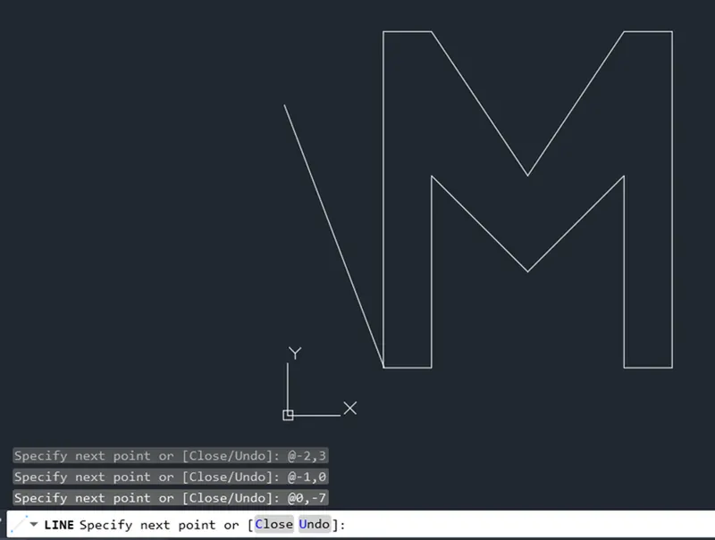
Step of creating geometry in AutoCAD software by Relative polar coordinate:-
- Type the command “L” for the line and specify the coordinate for starting point 1 (2,1)
- Type the next coordinate of point 2 @1 <0 in the command box
- Type the next coordinate of point 3 @4 <90 in the command box
- Type the next coordinate of point 10@2 <0 in the command box
- Type the next coordinate of point 4@2<270 in the command box
- Cancel the line command by pressing enter.
- Now use line command “L” and join point 3and point 4 and cancel the line command by pressing enter. And then delete line joining from point 3 to 10 and point 10 to 4
- Type the command “ L” and specify the point 4 (5,3) and type the next coordinate of point 10@2<90 in the command box.
- Type the coordinate of point 5@2<0 in the command box.
- Cancel the line command by pressing enter.
- Now use line command “L” and join point 4 and point 5 and cancel the line command by pressing enter. And delete line joining from point 4 to 10 and point 10 to 5.
- Type the command “L” and specify the start point 5 (7,5) and type the next coordinate of point 6 @4<270 in the command box.
- Type the next coordinate of point 7 @1< 0 in the command box.
- Type the next coordinate of point 8@1<90 in the command box.
- Type the next coordinate of point 9 @1<180 in the command box.
- Type the next coordinate of point 5 @3<270 in the command box.
- Type the next coordinate of point 10 @2<180 in the command box.
- Cancel the line command by pressing enter.
- Now use line command “L” and join point 9 and point 10 and cancel the line command by pressing enter. and delete lines joining from point 9 to 5 and point 5 to 10.
- Type the command “L” and specify the start point 10 (5,5) and type the next coordinate of point 3 @2<180 in the command box.
- Type the next coordinate of point 11 @3<90 in the command box.
- Cancel the line command by pressing enter.
- Now use line command “L” and join point 10 and point 11 and cancel the line command by pressing enter. And delete lines joining from point 10 to 3 and point 3 to 11.
- Type the command “L” specify the start point 11 (3,8) and type the next coordinate of point 12 @1<180 in the command box.
- Type the next coordinate of point 1 @7<270 in the command box and cancel the line command by pressing enter.
Result :-
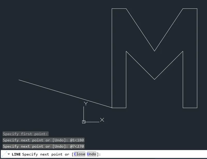
Step of creating geometry in AutoCAD software by Direct Distance Entry:-
- Type the command " L " for the line and specify the coordinate for Starting point 1 ( 2,1 ) .
- Type the length 1 in command box to + ve x - axis for point 2 .
- Type the length 4 in command box to + ve y - axis for point 3 .
- Type the length 2 in command box to + ve x - axis for point 10 and then type the length 2 in command box to -ve y - axis for point 4 .
- Cancel the command by pressing enter and then type the command " L " and join point 3 and point 4 .
- Cancel the command by pressing enter and delete the other lines joining from point 3 to 10 and point 10 to 4 .
- Type the command “ L “ specify the start point 4 ( 5,3 ) and type the length 2 in command box to + ve y - axis for point 10 and type the length 2 in command box to ve x - axis for point 5 .
- Cancel the command by pressing enter . and then type the command “ L “ and join point 4 and point 5 .
- Cancel the Line command by pressing enter . And delete lines joining from point 4 to 10 and point 10 to 5 .
- Type the command “ L “ specify the start point 5 ( 7,5 ) and type the length 4 in command box to -ve y - axis for point 6 .
- Type the length 1 in command box to + ve x - axis for point 7 .
- Type the length 7 in command box to + ve y - axis for point B.
- Type the length 1 in command box to - ve x - axis for point 9 .
- Type the length 3 in command box to - ve y - axis for point 5 and type the length 2 in command box to - ve x - axis for point 10
- Cancel the Line command by pressing enter .
- Now use line command “ L “ and join Point 9 and point 10 and cancel the Line command by pressing enter . And delete lines joining from point 9 to 5 and point 5 to 10 .
- Type the command “ L “ specify the start point 10 ( 5,5 ) and type the length 2 in command box to - ve x - axis for point 3 and type the length 3 in command box to + ve y - axis for point 11.
- Cancel the Line command by pressing enter .
- Now use line command “ L “ and join Point 10 and point 11 and cancel the Line command by pressing enter . And delete lines joining from point 10 to 3 and point 3 to 11 .
- Type the command “ L “ specify the start point 11 ( 3,8 ) and type the length 1 in command box to – ve x - axis for point 12
21 Type the length 7 in command box to - ve y - axis for point 1 and cancel the Line command by pressing enter.
Click “Close” on the command box.
Result:-
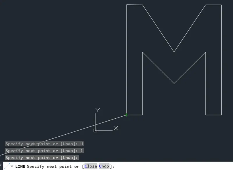
Aim : create the geometry of given picture in AutoCAD using all the coordinate system methods.
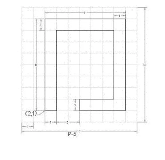
Procedure :-
Step 1: on opening the AutoCAD software , step the units imperial template and decimal system to 0.000.
Step 2: set the limits in commercial tab using “ LIM ‘’ before drafting.
Now,
Step of creating geometry in AutoCAD software by Absolute coordinate system :-
- Type the command “L” for the line and specify the coordinate for starting points 1 (2,1)
- Type the next coordinate of point 2 (3,1) in the command box .
- Type the next coordinate of point 3 (3,8) in the command box .
- Type the next coordinate of point 4 (8,8) in the command box .
- Type the next coordinate of point 5 (8,2) in the command box .
- Type the next coordinate of point 6 (5,2) in the command box .
- Type the next coordinate of point 7 (5,1) in the command box .
- Type the next coordinate of point 8 (9,1) in the command box .
- Type the next coordinate of point 9 (9,9) in the command box .
- Type the next coordinate of point 10 (2,9) in the command box .
- Click “close “ on the command box
Result :-
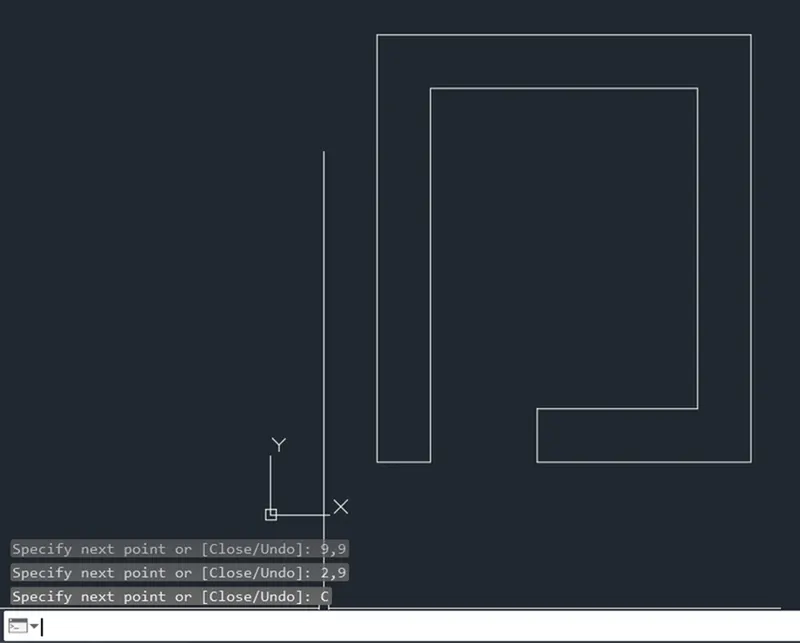
Step of creating in AutoCAD software by Relative Rectangular coordinate system :-
- Type the command “L” for the line and specify the coordinate for starting points 1 (2,1)
- Type the next coordinate of point 2 @1,0 in the command box .
- Type the next coordinate of point 3 @0,7 in the command box .
- Type the next coordinate of point 4 @5,0 in the command box .
- Type the next coordinate of point 5 @0.-6 in the command box .
- Type the next coordinate of point 6 @-3,0 in the command box .
- Type the next coordinate of point 7 @0,-1 in the command box .
- Type the next coordinate of point 8 @4,0 in the command box .
- Type the next coordinate of point 9 @0,8 in the command box .
- Type the next coordinate of point 10 @-7, 0 in the command box .
- Click “close” on the command box
Result :-
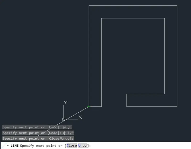
Steps of creating geometry in AutoCAD software by Relative polar coordinate :-
- Type the command “L” for the line and specify the coordinate for starting points 1 (2,1)
- Type the next coordinate of point 2 @1<0 in the command box .
- Type the next coordinate of point 3 @7<90 in the command box .
- Type the next coordinate of point 4 @5<0 in the command box .
- Type the next coordinate of point 5 @6<270 in the command box .
- Type the next coordinate of point 6 @1<180 in the command box .
- Type the next coordinate of point 7 @0<270in the command box .
- Type the next coordinate of point 8 @4<0 in the command box .
- Type the next coordinate of point 9 @8<90 in the command box .
- Type the next coordinate of point 10 @7<180 in the command box .
- Click “close” on the command box
Result :-
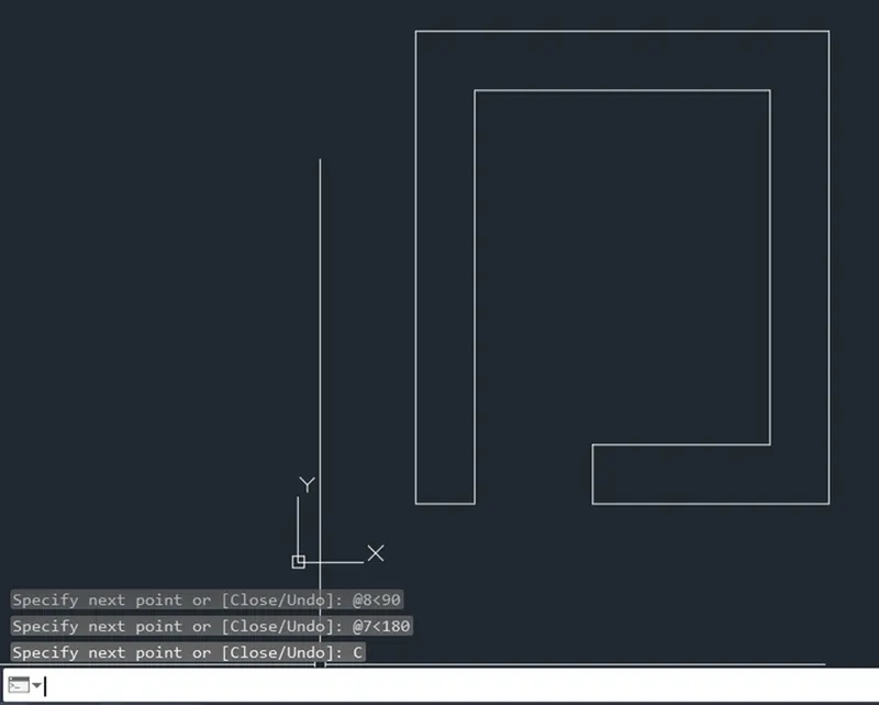
Steps to create geometry in AutoCAD software by Direct Distance Entry:-
- Type the command “L” for the line and specify the coordinate for starting points 1 (2,1)
- Type the length 1 in command box to +ve x- axis for point 2.
- Type the length 7 in command box to +ve y- axis for point 3.
- Type the length 5 in command box to +ve x- axis for point 4.
- Type the length 6 in command box to -ve y- axis for point 5.
- Type the length 3 in command box to -ve x- axis for point 6.
- Type the length 1 in command box to -ve y- axis for point 7.
- Type the length 4 in command box to +ve x- axis for point 8.
- Type the length 8 in command box to +ve y- axis for point 9.
- Type the length 7 in command box to -ve x- axis for point 10.
- Click “ Close” on the command box
Result :-
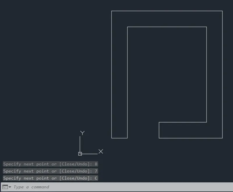
Aim : create the geometry of given picture in AutoCAD using all the coordinate system methods.
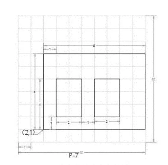
Procedure :-
Step 1: on opening the AutoCAD software , step the units imperial template and decimal system to 0.000.
Step 2: set the limits in commercial tab using “ LIM ‘’ before drafting.
Now,
Step of creating geometry in AutoCAD software by Absolute coordinate system :-
- Type the command “L” for the line and specify the coordinate for starting points 1 (2,1)
- Type the next coordinate of point 2 (10,1) in the command box .
- Type the next coordinate of point 3 (10,7) in the command box .
- Type the next coordinate of point 4 (2,7) in the command box .
- Click “ close” on the command box.
- Type the command “L” for the line and specify the coordinate for 5 (3,2) .
- Type the next coordinate of point 6 (5,2) in the command box .
- Type the next coordinate of point 7 (5,5) in the command box .
- Type the next coordinate of point 8 (3,5) in the command box .
- Click “close” on the command box
- Type the command “L” for the line and specify the coordinate for point 9 (6,2).
- Type the next coordinate of point 10 (8,2) in the command box .
- Type the next coordinate of point 11 (8,5) in the command box .
- Type the next coordinate of point 12 (6,5) in the command box .
- Click “close” on the command box
Result :-
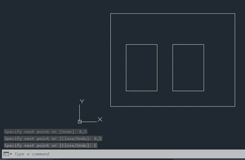
Steps of creating geometry in AutoCAD Software by Relative Rectangular Coordinate System :
- Type the command " L " for the line and specify the coordinate for Starting point 1 ( 2,1 ) .
- Type the next coordinate of point 2 @ 8,0 in the command box .
- Type the next coordinate of point 3 @ 0,6 in the command box . 4.
Type the next coordinate of point 4 @ -8,0 in the command box .
- Click " close " on the command box .
- Type the command " L " for the line and specify the coordinate for point 5 ( 3,2 ) .
- Type the next coordinate of point 6 @ 2,0 in the command box .
- Type the next coordinate of point 7 @ 0,3 in the command box .
- Type the next coordinate of point 8 @ -2,0 in the command box .
- Click " close " on the command box .
- Type the command " L " for the line and specify the coordinate for point 9 ( 6,2 ) .
- Type the next coordinate of point 10 @ 2,0 in the command box .
- Type the next coordinate of point 11 @ 0,3 in the command box .
- Type the next coordinate of point 12 @ -2,0 in the command box . 15. Click " close " on the command box
RESULT
:
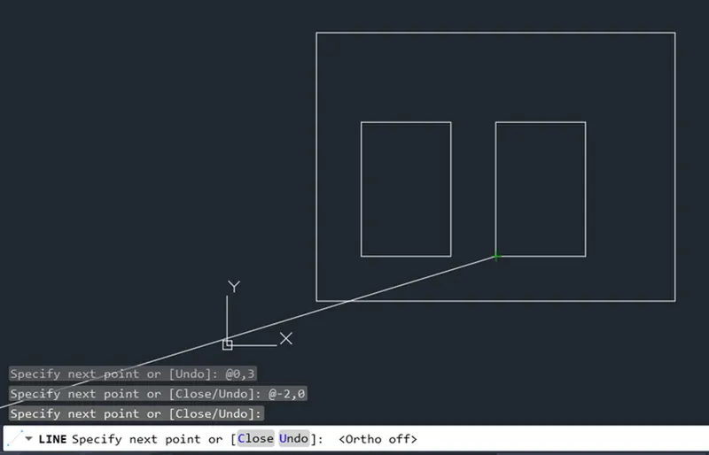
Steps of creating geometry in AutoCAD software by Relative polar coordinate :-
- Type the command “L” for the line and specify the coordinate for starting points 1 (2,1)
- Type the next coordinate of point 2 @8<0 in the command box .
- Type the next coordinate of point 3 @6<90 in the command box .
- Type the next coordinate of point 4 @8<180 in the command box .
- Click “Close” on the command box.
- Type the command “L” for the line and specify the coordinate for point 5 (3,2)
- Type the next coordinate of point 6@2<0 in the command box .
- Type the next coordinate of point 7 @3<90 in the command box .
- Type the next coordinate of point 8@2<180in the command box .
- Click “Close” on the command box.
- Type the command “L” for the line and specify the coordinate for point 9 (6,2)
- Type the next coordinate of point 10@2<0 in the command box .
- Type the next coordinate of point 11@3<90 in the command box .
- Type the next coordinate of point 12 @2<180 in the command box .
- Click “close” on the command box
Result :
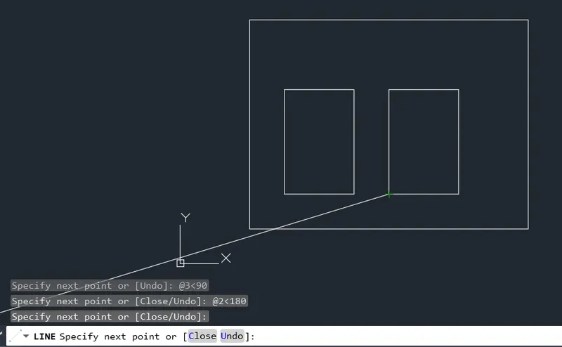
Steps of creating geometry in AutoCAD Software by Direct Distance Entry :
- Type the command " L " for the line and specify the coordinate for Starting point 1 ( 2,1 ) .
- Type the length 8 in command box to + ve x - axis for point 2 .
- Type the length 6 in command box to + ve y - axis for point 3 .
- Type the length 8 in command box to -ve x - axis for point 4 .
- Click " close " on the command box .
- Type the command " L " for the line and specify the coordinate for point 5 ( 3,2 ) .
- Type the length 2 in command box to + ve x - axis for point 6 .
- Type the length 3 in command box to + ve y - axis for point 7 .
- Type the length 2 in command box to -ve x - axis for point 8 .
- Click " close " on the command box .
- Type the command " L " for the line and specify the coordinate for point 9 ( 6,2 ) .
- Type the length 2 in command box to + ve x - axis for point 10 .
- Type the length 3 in command box to + ve y - axis for point 11 .
- Type the length 2 in command box to -ve x - axis for point 12 .
- Click " close " on the command box
RESULT :
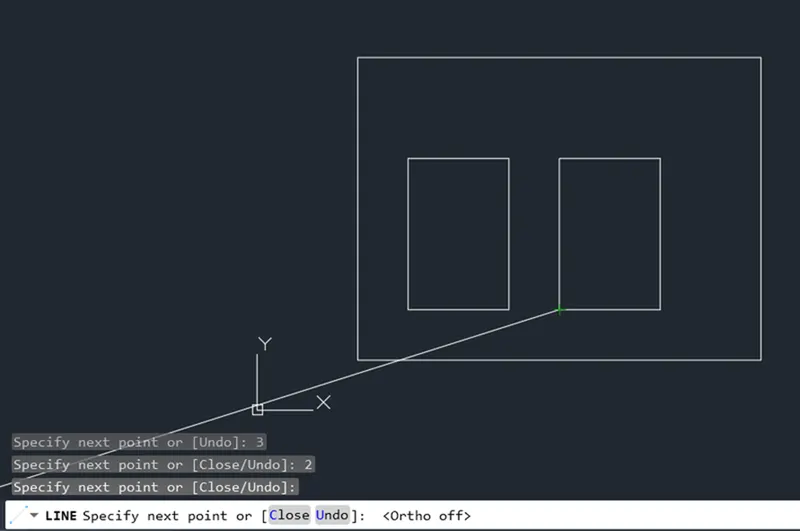
Aim : create geometry of given picture in AutoCAD using all the coordinate system method :-
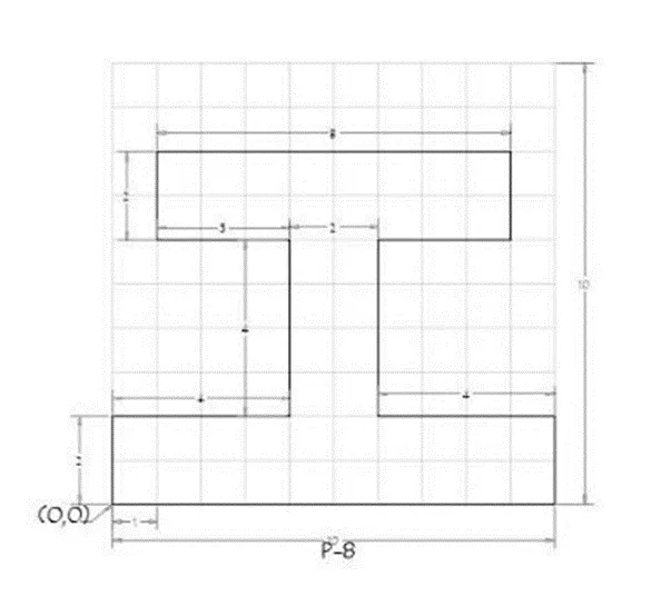
PROCEDURE :
STEP 1 : On opening the AutoCAD software , setup the units to Imperial template and decimal system 0.000 .
STEP 2 : Set the limits in the command tab using " LIM " before drafting .
Now ,
Steps of creating geometry in AutoCAD Software by Absolute coordinate system :
- Type the command " L " for the line and specify the coordinate for Starting point 1 ( 0,0 ) .
- Type the next coordinate of point 2 ( 10,0 ) in the command box .
- Type the next coordinate of point 3 ( 10,2 ) in the command box .
- Type the next coordinate of point 4 ( 6,2 ) in the command box .
- Type the next coordinate of point 5 ( 6,6 ) in the command box .
- Type the next coordinate of point 6 ( 9,6 ) in the command box .
- Type the next coordinate of point 7 ( 9,8 ) in the command box .
- Type the next coordinate of point 8 ( 1,8 ) in the command box .
- Type the next coordinate of point 9 ( 1,6 ) in the command box .
- Type the next coordinate of point 10 ( 4,6 ) in the command box .
- Type the next coordinate of point 11 ( 4,2 ) in the command box .
- Type the next coordinate of point 12 ( 0,2 ) in the command box .
- Click " close " on the command box.
RESULT :
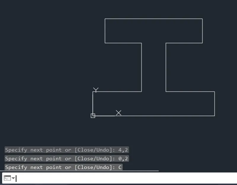
Steps of creating geometry in AutoCAD Software by Relative Rectangular Coordinate System :
- Type the command " L " for the line and specify the coordinate for Starting point 1 ( 0,0 ) .
- Type the next coordinate of point 2 @ 10,0 in the command box .
- Type the next coordinate of point 3 @ 0,2 in the command box .
- Type the next coordinate of point 4 @ -4,0 in the command box .
- Type the next coordinate of point 5 @ 0,4 in the command box .
- Type the next coordinate of point 6 @ 3,0 in the command box .
- Type the next coordinate of point 7 @ 0,2 in the command box .
- Type the next coordinate of point 8 @ -8,0 in the command box .
- Type the next coordinate of point 9 @ 0 , -2 in the command box .
- Type the next coordinate of point 10 @ 3,0 in the command box .
- Type the next coordinate of point 11 @ 0 , -4 in the command box .
- Type the next coordinate of point 12 @ -4,0 in the command box .
- Click " close " on the command box.
RESULT :
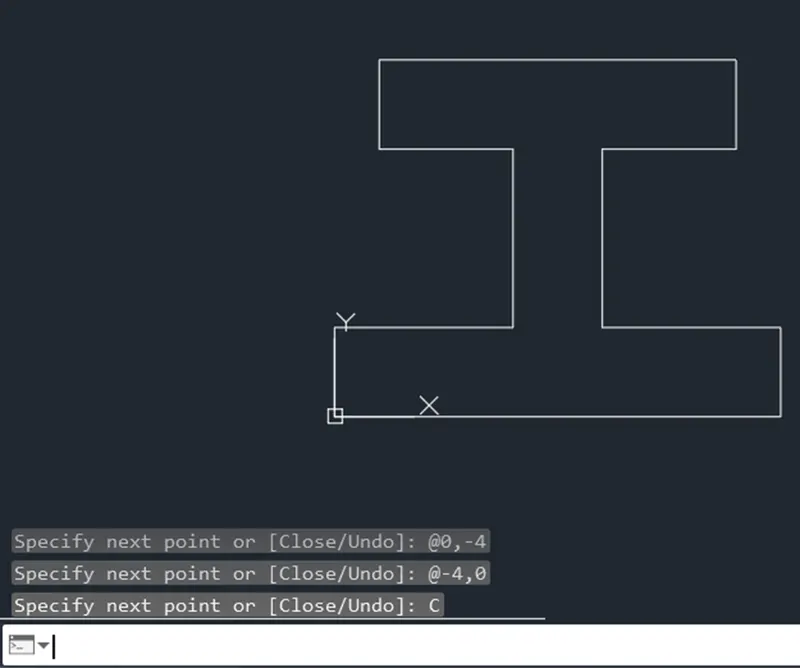
Steps of creating geometry in AutoCAD Software by Relative Polar coordinate :
- Type the command " L " for the line and specify the coordinate for Starting point 1 ( 0,0 ) .
- Type the next coordinate of point 2 @ 10 < 0 in the command box .
- Type the next coordinate of point 3 @ 2 < 90 in the command box .
- Type the next coordinate of point 4 @ 4 < 180 in the command box .
- Type the next coordinate of point 5 @ 4 < 90 in the command box .
- Type the next coordinate of point 6 @ 3 < 0 in the command box .
- Type the next coordinate of point 7 @ 2 < 90 in the command box .
- Type the next coordinate of point 8 @ 8 < 180 in the command box .
- Type the next coordinate of point 9 @ 2 < 270 in the command box .
- Type the next coordinate of point 10 @ 3 < 0 in the command box .
- Type the next coordinate of point 11 @ 4 < 270 in the command box .
- Type the next coordinate of point 12 @ 4 < 180 in the command box .
- Click " close " on the command box.
RESULT :
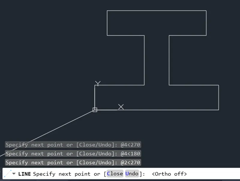
Steps of creating geometry in AutoCAD Software by Direct Distance Entry :
- Type the command " L " for the line and specify the coordinate for Starting point 1 ( 0,0 ) .
- Type the length 10 in command box to + ve x - axis for point 2 .
- Type the length 2 in command box to + ve y - axis for point 3 .
- Type the length 4 in command box to -ve x - axis for point 4 .
- Type the length 4 in command box to + ve y - axis for point 5 .
- Type the length 3 in command box to + ve x - axis for point 6 .
- Type the length 2 in command box to + ve y - axis for point 7 .
- Type the length 8 in command box to -ve x - axis for point 8 .
- Type the length 2 in command box to -ve y - axis for point 9 .
- Type the length 3 in command box to + ve x - axis for point 10 .
- Type the length 4 in command box to -ve y - axis for point 11 .
- Type the length 4 in command box to -ve x - axis for point 12 .
- Click " close " on the command box.
RESULT :
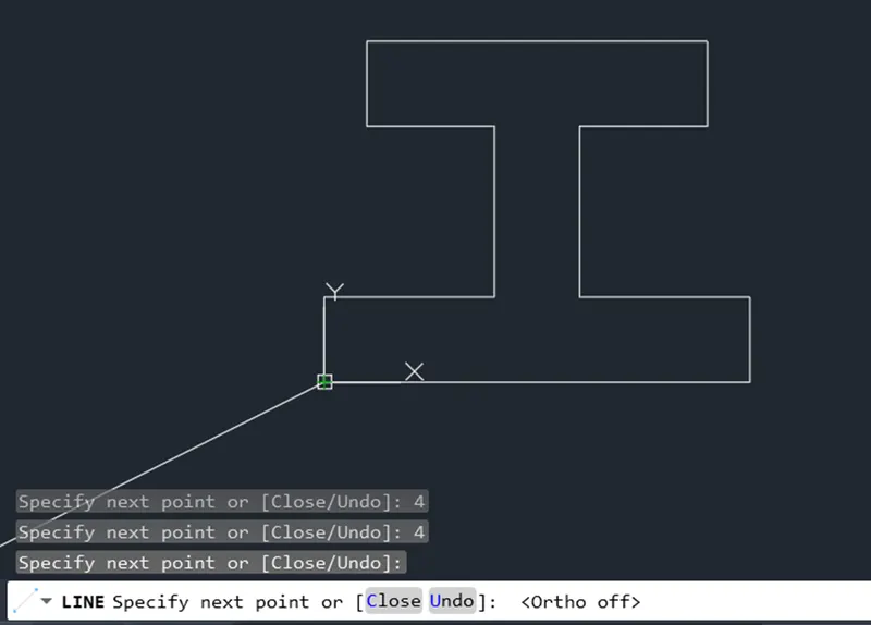
Step of create geometry in AutoCAD software using all the coordinate system method :
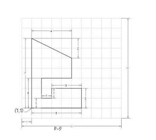
PROCEDURE :
STEP 1 : On opening the AutoCAD software , setup the units to Imperial template and decimal system to 0.000 .
STEP 2 : Set the limits in the command tab using " LIM " before drafting .
Now ,
Steps of creating geometry in AutoCAD Software by Absolute coordinate system :
- Type the command " L " for the line and specify the coordinate for Starting point 1 ( 1,1 ) .
- Type the next coordinate of point 2 ( 6,1 ) in the command box .
- Type the next coordinate of point 3 ( 6,3 ) in the command box .
- Type the next coordinate of point 4 ( 3,3 ) in the command box .
- Type the next coordinate of point 5 ( 3,2 ) in the command box .
- Type the next coordinate of point 6 ( 2,2 ) in the command box .
- Type the next coordinate of point 7 ( 2,4 ) in the command box .
- Type the next coordinate of point 8 ( 5,4 ) in the command box .
- Type the next coordinate of point 9 ( 5,6 ) in the command box .
- Type the next coordinate of point 10 ( 1,8 ) in the command box .
- Click " close " on the command box.
RESULT :
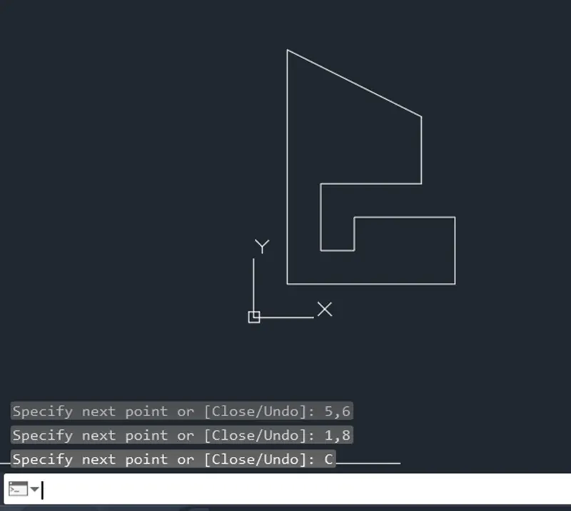
Steps of creating geometry in AutoCAD Software by Relative Rectangular Coordinate System :
- Type the command " L " for the line and specify the coordinate for Starting point 1 ( 1,1 ) .
- Type the next coordinate of point 2 @ 5,0 in the command box .
- Type the next coordinate of point 3 @ 0,2 in the command box .
- Type the next coordinate of point 4 @ -3,0 in the command box .
- Type the next coordinate of point 5 @ 0 , -1 in the command box .
- Type the next coordinate of point 6 @ -1,0 in the command box .
- Type the next coordinate of point 7 @ 0,2 in the command box .
- Type the next coordinate of point 8 @ 3,0 in the command box .
- Type the next coordinate of point 9 @ 0,2 in the command box .
- Type the next coordinate of point 10 @ -4,2 in the command box .
- Click " close " on the command box.
RESULT :
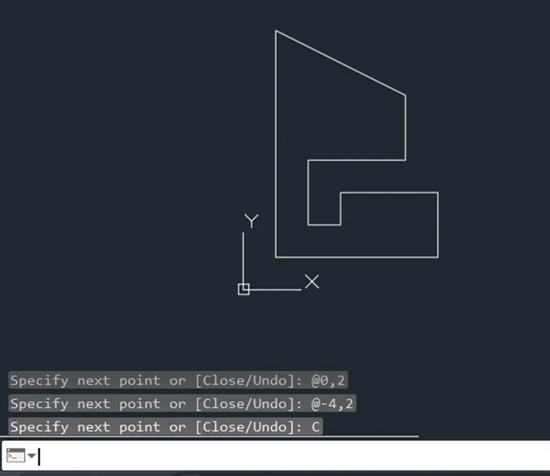
Steps of creating geometry in AutoCAD Software by Relative Polar coordinate :
- Type the command " L " for the line and specify the coordinate for Starting point 1 ( 1,1 ) .
- Type the next coordinate of point 2 @ 5 < 0 in the command box .
- Type the next coordinate of point 3 @ 2 < 90 in the command box .
- Type the next coordinate of point 4 @ 3 < 180 in the command box .
- Type the next coordinate of point 5 @ 1 < 270 in the command box .
- Type the next coordinate of point 6 @ 1 < 180 in the command box .
- Type the next coordinate of point 7 @ 2 < 90 in the command box .
- Type the next coordinate of point 8 @ 3 < 0 in the command box .
- Type the next coordinate of point 9 @ 2 < 90 in the command box .
- Type the next coordinate of point 11 @ 2 < 90 in the command box .
- Type the next coordinate of point 10 @ 4 < 180 in the command box .
- Cancel the Line command by pressing Enter .
- Now use line command " L " and join Point 9 and point 10 and cancel the Line command by pressing Enter . And delete lines joining from point 9 to 11 and point 11 to 10 .
- Type the command " L " and specify the start point 10 ( 1,8 ) and type the next coordinate of point 1 @ 7 < 270 in the command box .
- Cancel the Line command by pressing Enter .
RESULT :
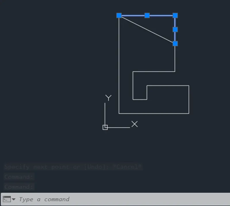
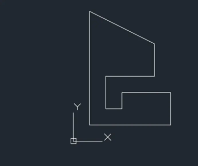
Steps of creating geometry in AutoCAD Software by Direct Distance Entry :
- Type the command " L " for the line and specify the coordinate for Starting point 1 ( 1,1 ) .
- Type the length 5 in command box to + ve x - axis for point 2 .
- Type the length 2 in command box to + ve y - axis for point 3 .
- Type the length 3 in command box to -ve x - axis for point 4 .
- Type the length 1 in command box to -ve y - axis for point 5 .
- Type the length 1 in command box to -ve x - axis for point 6 .
- Type the length 2 in command box to + ve y - axis for point 7 .
- Type the length 3 in command box to + ve x - axis for point 8 .
- Type the length 2 in command box to + ve y - axis for point 9 .
- Type the length 2 in command box to + ve y - axis for point 11 and then type the length 4 in command box to -ve x - axis for point 10 .
- Cancel the Line command by pressing Enter and again then type Line command " L " and join point 9 and point 10 and then cancel the Line command by pressing Enter .
- Delete the lines joining from point 9 to 11 and point 11 to 10 .
- Type the command " L " and specify the start point 10 ( 1,8 ) and type the length 7 in command box to -ve y - axis for point 1 .
- Cancel the Line command by pressing Enter .
RESULT :
Aim : create the geometry of given picture AutoCAD using all the coordinate system methods.
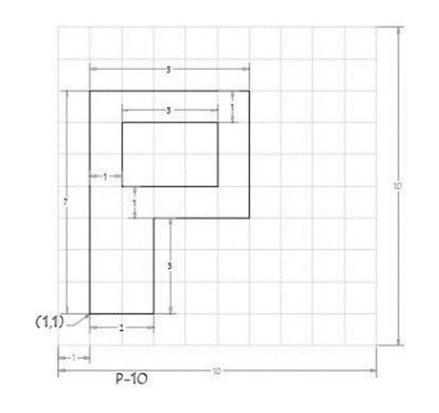
PROCEDURE :
STEP 1 : On opening the AutoCAD software , setup the units to Imperial template and decimal system to 0.000 .
STEP 2 : Set the limits in the command tab using " LIM " before drafting .
Now ,
Steps of creating geometry in AutoCAD Software by Absolute coordinate system :
- Type the command " L " for the line and specify the coordinate for Starting point 1 ( 1,1 ) .
- Type the next coordinate of point 2 ( 3,1 ) in the command box .
- Type the next coordinate of point 3 ( 3,4 ) in the command box .
- Type the next coordinate of point 4 ( 6,4 ) in the command box .
- Type the next coordinate of point 5 ( 6,8 ) in the command box .
- Type the next coordinate of point 6 ( 1,8 ) in the command box .
- Click " close " on the command box .
- Type the command " L " for the line and specify the coordinate for point 7 ( 2,5 ) .
- Type the next coordinate of point 8 ( 5,5 ) in the command box .
- Type the next coordinate of point 9 ( 5,7 ) in the command box .
- Type the next coordinate of point 10 ( 2,7 ) in the command box .
- Click " close " on the command box .
RESULT :
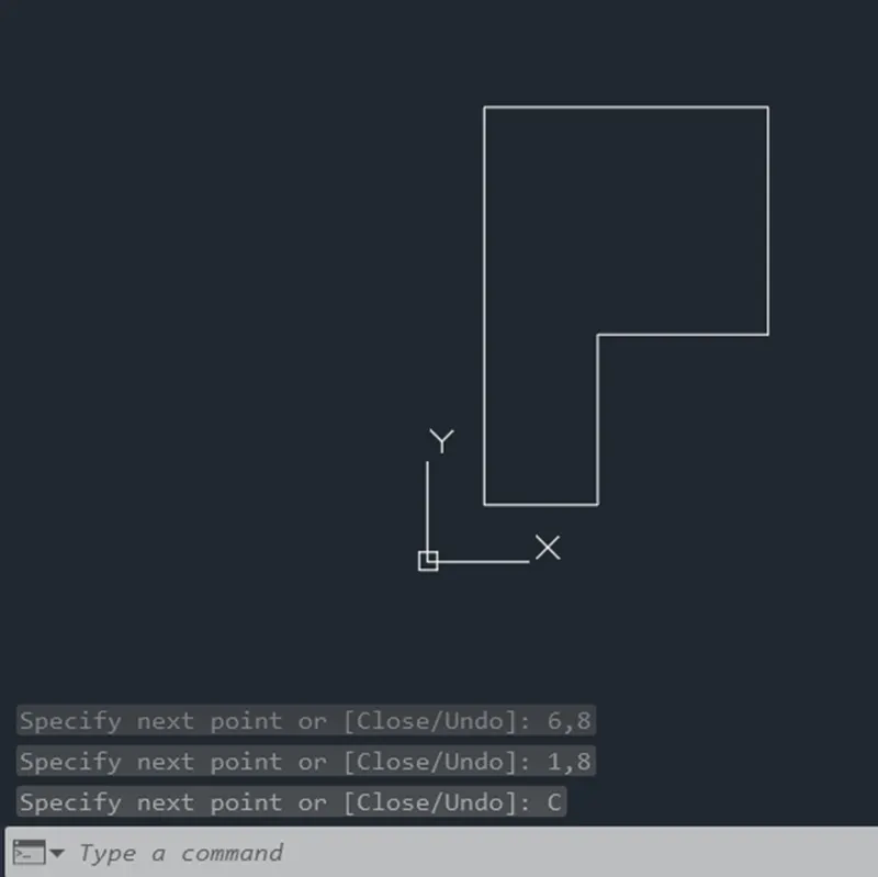
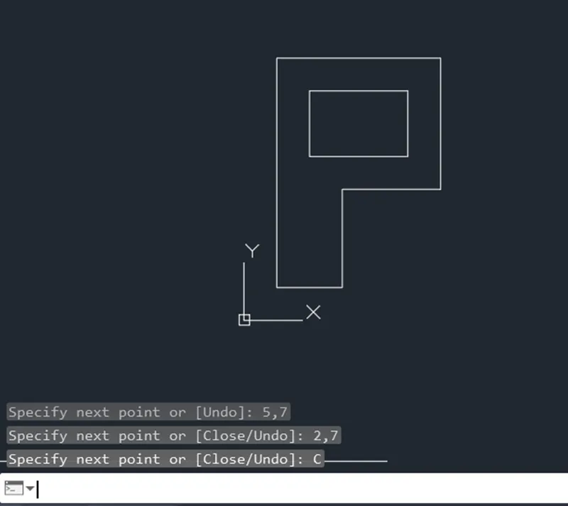
Steps of creating geometry in AutoCAD Software by Relative Rectangular Coordinate System :
- Type the command " L " for the line and specify the coordinate for Starting point 1 ( 1,1 ) .
- Type the next coordinate of point 2 @ 2,0 in the command box .
- Type the next coordinate of point 3 @ 0,3 in the command box .
- Type the next coordinate of point 4 @ 3,0 in the command box .
- Type the next coordinate of point 5 @ 0,4 in the command box .
- Type the next coordinate of point 6 @ -5,0 in the command box .
- Click " close " on the command box .
- Type the command " L " for the line and specify the coordinate for point 7 ( 2,5 ) .
- Type the next coordinate of point 8 @ 3,0 in the command box .
- Type the next coordinate of point 9 @ 0,2 in the command box .
- Type the next coordinate of point 10 @ -3,0 in the command box .
- Click " close " on the command box .
RESULT :
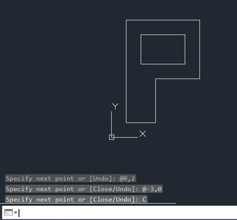
Steps of creating geometry in AutoCAD Software by Relative Polar coordinate :
- Type the command " L " for the line and specify the coordinate for Starting point 1 ( 1,1 ) .
- Type the next coordinate of point 2 @ 2 < 0 in the command box .
- Type the next coordinate of point 3 @ 3 < 90 in the command box .
- Type the next coordinate of point 4 @ 3 < 0 in the command box .
- Type the next coordinate of point 5 @ 4 < 90 in the command box .
- Type the next coordinate of point 6 @ 5 < 180 in the command box .
- Click " close " on the command box .
- Type the command " L " for the line and specify the coordinate for point 7 ( 2,5 ) .
- Type the next coordinate of point 8 @ 3 < 0 in the command box .
- Type the next coordinate of point 9 @ 2 < 90 in the command box .
- Type the next coordinate of point 10 @ 3 < 180 in the command box .
- Click " close " on the command box .
RESULT :
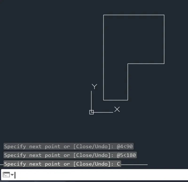
Steps of creating geometry in AutoCAD Software by Direct Distance Entry :
- Type the command " L " for the line and specify the coordinate for Starting point 1 ( 1,1 ) .
- Type the length 2 in command box to + ve x - axis for point 2 .
- Type the length 3 in command box to + ve y - axis for point 3 .
- Type the length 3 in command box to + ve x - axis for point 4 .
- Type the length 4 in command box to + ve y - axis for point 5 .
- Type the length 5 in command box to -ve x - axis for point 6 .
- Click " close " on the command box .
- Type the command " L " for the line and specify the coordinate for point 7 ( 2,5 ) .
- Type the length 3 in command box to + ve x - axis for point 8 .
- Type the length 2 in command box to + ve y - axis for point 9 .
- Type the length 3 in command box to -ve x - axis for point 10 .
- Click " close " on the command box .
RESULT :
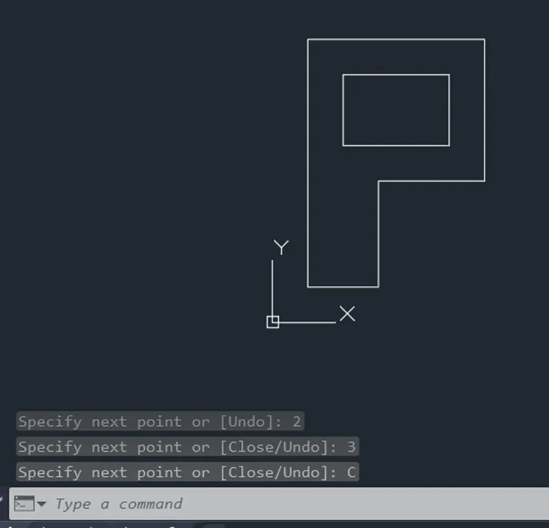
Aim : create the geometry of given picture in AutoCAD using coordinates system method .
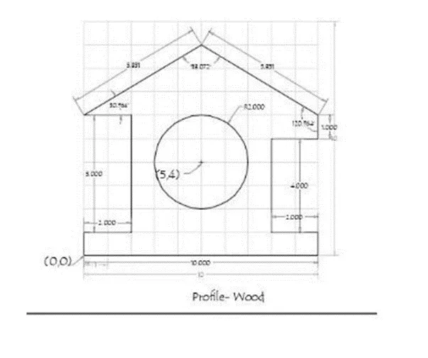
PROCEDURE :
STEP 1 : On opening the AutoCAD software , setup the units to Imperial template and decimal system to 0.000 .
STEP 2 : Set the limits in the command tab using " LIM " before drafting .
Now ,
Steps of creating geometry in AutoCAD Software by Absolute coordinate system :
- Type the command " L " for the line and specify the coordinate for Starting point 1 ( 0,0 ) .
- Type the next coordinate of point 2 ( 10,0 ) in the command box .
- Type the next coordinate of point 3 ( 10,1 ) in the command box .
- Type the next coordinate of point 4 ( 8,1 ) in the command box .
- Type the next coordinate of point 5 ( 8,5 ) in the command box .
- Type the next coordinate of point 6 ( 10,5 ) in the command box .
- Type the next coordinate of point 7 ( 10,6 ) in the command box .
- Type the next coordinate of point 8 ( 5,9 ) in the command box .
- Type the next coordinate of point 9 ( 0,6 ) in the command box .
- Type the next coordinate of point 10 ( 2,6 ) in the command box .
- Type the next coordinate of point 11 ( 2,1 ) in the command box .
- Type the next coordinate of point 12 ( 0,1 ) in the command box .
- Click " close " on the command box .
- Type the command " C " for the circle and specify the coordinate of centre of circle as point 13 ( 5,4 ) .
- Type the Radius 2 in command box and press enter .
RESULT :
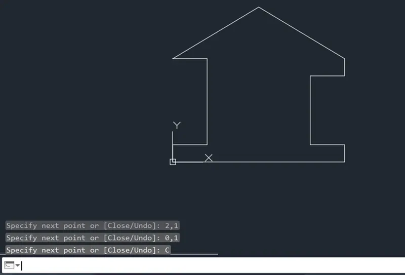
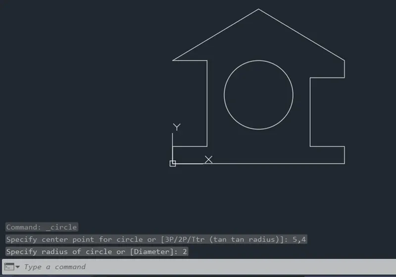
Steps of creating geometry in AutoCAD Software by Relative Rectangular Coordinate System :
- Type the command " L " for the line and specify the coordinate for Starting point 1 ( 0,0 ) .
- Type the next coordinate of point 2 @ 10,0 in the command box .
- Type the next coordinate of point 3 @ 0,1 in the command box .
- Type the next coordinate of point 4 @ -2,0 in the command box .
- Type the next coordinate of point 5 @ 0,4 in the command box .
- Type the next coordinate of point 6 @ 2,0 in the command box .
- Type the next coordinate of point 7 @ 0,1 in the command box .
- Type the next coordinate of point 8 @ -5,3 in the command box .
- Type the next coordinate of point 9 @ -5 , -3 in the command box .
- Type the next coordinate of point 10 @ 2,0 in the command box .
- Type the next coordinate of point 11 @ 0 , -5 in the command box .
- Type the next coordinate of point 12 @ -2,0 in the command box .
- Click " close " on the command box .
- Type the command " C " for the circle and specify the coordinate of centre of circle as point 13 ( 5,4 ) .
- Type the Radius 2 in command box and press enter .
RESULT :
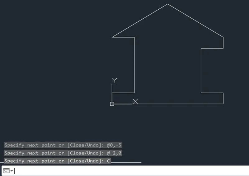
Steps of creating geometry in AutoCAD Software by Relative Polar coordinate :
- Type the command " L " for the line and specify the coordinate for Starting point 1 ( 0,0 ) .
- Type the next coordinate of point 2 @ 10 < 0 in the command box .
- Type the next coordinate of point 3 @ 1 < 90 in the command box .
- Type the next coordinate of point 4 @ 2 < 180 in the command box .
- Type the next coordinate of point 5 @ 4 < 90 in the command box .
- Type the next coordinate of point 6 @ 2 < 0 in the command box .
- Type the next coordinate of point 7 @ 1 < 90 in the command box .
- Type the next coordinate of point 14 @ 3 < 90 in the command box .
- Type the next coordinate of point 8 @ 5 < 180 in the command box .
- Cancel the command by pressing Enter .
- Now use line command " L " and join Point 7 and point 8 and then cancel the command by pressing Enter .
- Delete lines joining from point 7 to 14 and point 14 to 8 .
- Type the command " L " specify the start point 8 ( 5,9 ) and type the next coordinate of point 15 @ 5 < 180 in the command box .
- Type the next coordinate of point 9 @ 3 < 270 in the command box .
- Cancel the command by pressing Enter .
- Now use line command " L " and join Point 8 and point 9 and then cancel the command by pressing Enter .
- Delete lines joining from point 8 to 15 and point 15 to 9 .
- Type the command " L " specify the start point 9 ( 0,6 ) and type the next coordinate of point 10 @ 2 < 0 in the command box .
- Type the next coordinate of point 11 @ 5 < 270 in the command box .
- Type the next coordinate of point 12 @ 2 < 180 in the command box .
- Click " close " on the command box .
- Type the command " C " for the circle and specify the coordinate of centre of circle as point 13 ( 5,4 ) .
- Type the Radius 2 in command box and press enter .
RESULT :
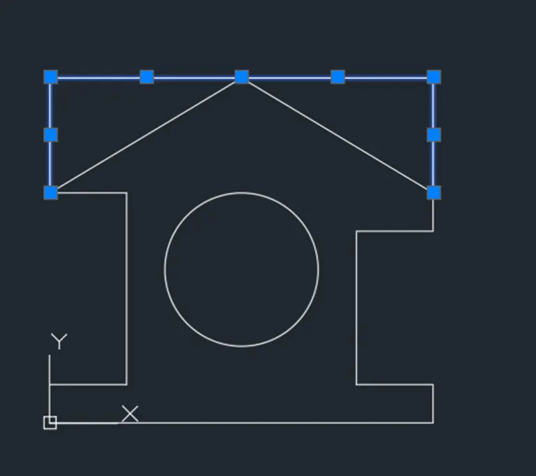
Steps of creating geometry in AutoCAD Software by Direct Distance Entry :
- Type the command " L " for the line and specify the coordinate for Starting point 1 ( 0,0 ) .
- Type the length 10 in command box to + ve x - axis for point 2 .
- Type the length 1 in command box to + ve y - axis for point 3 .
- Type the length 2 in command box to -ve x - axis for point 4 .
- Type the length 4 in command box to + ve y - axis for point 5 .
- Type the length 2 in command box to + ve x - axis for point 6 .
- Type the length 1 in command box to + ve y - axis for point 7 .
- Type the length 3 in command box to + ve y - axis for point 14 and type the length 5 in command box to -ve x axis for point 8 .
- Cancel the command by pressing Enter and again type Line command " L " and then join point 7 and point 8 .
- Delete the other lines joining point 7 and point 14 and point 14 and point 8 .
- Type the command " L " and specify the start point 8 ( 5,9 ) and type the length 5 in command box to -ve x - axis for point 15 and type the length 3 in command box to -ve y - axis for point 9 .
- Cancel the command by pressing Enter and again type Line command " L " and then join point 8 and point 9 .
- Delete the other lines joining point 8 and point 15 and point 15 and point 9 .
- Type the command " L " and specify the start point 9 ( 0,6 ) and then type the length 2 in command box to + ve x axis for point 10 .
- Type the length 5 in command box to -ve y - axis for point 11 .
- Type the length 2 in command box to -ve x - axis for point 12 .
- Type the length 1 in command box to -ve y - axis for point 1 and cancel the command by pressing Enter .
- Type the command " C " for the circle and specify the coordinate of centre of circle as point 13 ( 5,4 ) .
- Type the Radius 2 in command box and press enter.
Result :-
Aim : create the geometry of given picture in AutoCAD using all the coordinate system method.
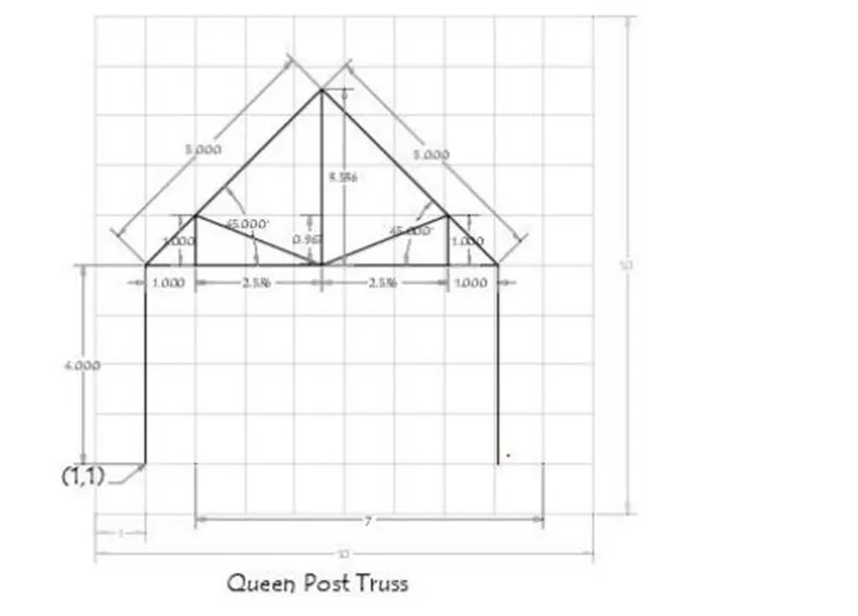
PROCEDURE :
- STEP 1 : On opening the AutoCAD software , setup the units to Imperial template and decimal system to 0.000 .
- STEP 2 : Set the limits in the command tab using " LIM " before drafting .
Now ,
Steps of creating geometry in AutoCAD Software by Absolute coordinate system :
- Type the command " L " for the line and specify the coordinate for Starting point 1 ( 1,1 ) .
- Type the next coordinate of point 2 ( 1,5 ) in the command box .
- Type the next coordinate of point 3 ( 4.5,8.5 ) in the command box .
- Type the next coordinate of point 4 ( 8,5 ) in the command box .
- Type the next coordinate of point 5 ( 8,1 ) in the command box .
- Cancel the command by pressing Enter .
- Type the command " L " for the line and join point 2 and point 4 and then cancel the line command by pressing enter .
- Type the command " I " for the line and type the next coordinate of point 6 ( 4.5,5 ) in the command box .
- Type the next coordinate of point 7 ( 2,6 ) in the command box .
- Type the next coordinate of point 8 ( 2,5 ) in the command box .
- Cancel the command by pressing Enter .
- Type the command " L " for the line and type the next coordinate of point 6 ( 4.5,5 ) in the command box .
- Type the next coordinate of point 9 ( 7,6 ) in the command box .
- Type the next coordinate of point 10 ( 7,5 ) in the command box .
- Cancel the command by pressing Enter .
- Type the command " L " for the line and join point 6 and point 3 and then cancel the line command by pressing . enter .
Result :-
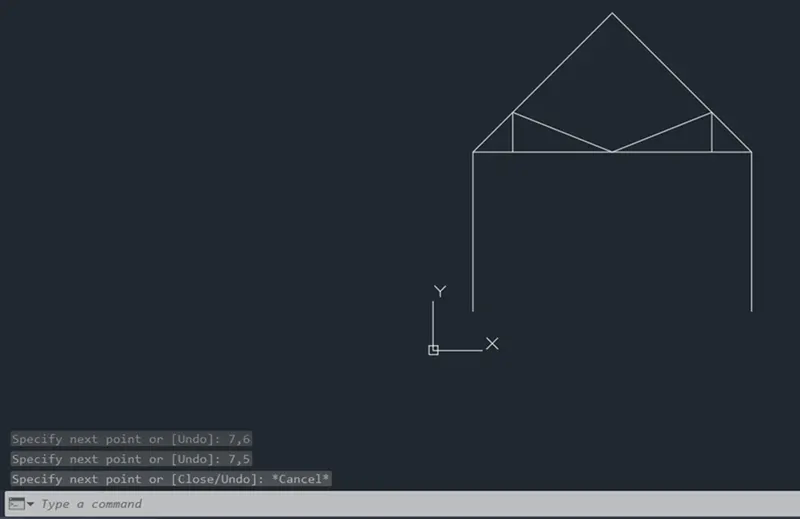
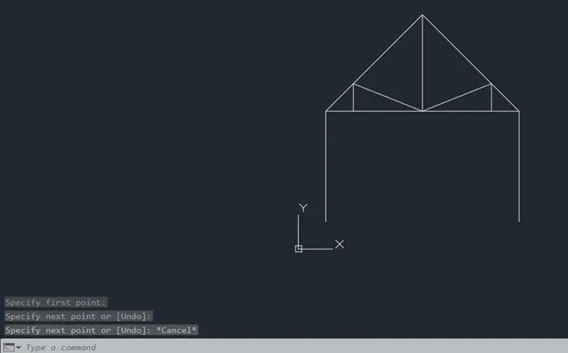
Steps of creating geometry in AutoCAD Software by Relative Rectangular Coordinate System :
- Type the command " L " for the line and specify the coordinate for Starting point 1 ( 1,1 ) .
- Type the next coordinate of point 2 @ 0,4 in the command box .
- Type the next coordinate of point 3 @ 3.5,3.5 in the command box .
- Type the next coordinate of point 4 @ 3.5 , -3.5 in the command box
- Type the next coordinate of point 5 @ 0 , -4 in the command box .
- Cancel the Line command by pressing enter .
- Type the command " L " for the line and join point 2 and point 4 and then cancel the line command by pressing enter .
- Type the command " L " for the line and type the next coordinate of point 6 @ 4.5,5 in the command box .
- Type the next coordinate of point 7 @ -2.5,1 in the command box .
- Type the next coordinate of point 8 @ 0 , -1 in the command box .
- Cancel the Line command by pressing enter .
- Type the command " L " for the line and type the next coordinate of point 6 @ 4.5,5 in the command box .
- Type the next coordinate of point 9 @ 2.5,1 in the command box .
- Type the next coordinate of point 10 @ 0 , -1 in the command box .
- Cancel the Line command by pressing enter .
- Type the command " L " for the line and join point 6 and point 3 and then cancel the line command by pressing enter .
Result :-
Steps of creating geometry in AutoCAD Software by Relative Polar coordinate :
- Type the command " L " for the line and specify the coordinate for Starting point 1 ( 1,1 ) .
- Type the next coordinate of point 2 @ 4 < 90 in the command box .
- Type the next coordinate of point 3 @ 5 < 45 in the command box .
- Type the next coordinate of point 4 @ 5 < 315 in the command box .
- Type the next coordinate of point 5 @ 4 < 270 in the command box .
- Cancel the Line command by pressing enter .
- Type the command " L " for the line and join point 2 and point 4 and then cancel the line command by pressing enter .
- Type the command " L " for the line and specify the cordinates for point 3 ( 4.5,8.5 ) .
- Type the next coordinate of point 6 @ 3.5 < 270 in the command box and then cancel the line command by pressing enter .
- Type the command " L " for the line and specify the cordinates for point 7 ( 2,6 ) .
- Type the next coordinate of point 8 @ 1 < 270 in the command box .
- Cancel the Line command by pressing enter .
- Type the command " L " for the line and join point 7 and point 6 and then cancel the line command by pressing enter .
- Type the command " L " for the line and specify the cordinates for point 9 ( 7,6 ) .
- Type the next coordinate of point 10 @ 1 < 270 in the command box .
- Cancel the Line by pressing enter .
- 17 , Type the command " L " for the line and join point 9 and point 6 and then cancel the line command by pressing enter .
RESULT
Steps of creating geometry in AutoCAD Software by Direct Distance Entry :
- Type the command " L " for the line and specify the coordinate for Starting point 1 ( 1,1 ) .
- Type the length 4 in command box to + ve y - axis for point 2 .
- Type the length 7 in command box to + ve x - axis for point 4 .
- Type the length 4 in command box to -ve y - axis for point 5 .
- Cancel the line command by pressing enter .
- Type the command " L " for the line and specify the coordinate for point 6 ( 4.5,5 ) .
- Type the length 3.5 in command box to + ve y - axis for point 3 .
- Cancel the command by pressing enter and again type Line command " L " and then join point 3 and point 2 .
- Cancel the command by pressing enter and again type Line command " L " and then join point 3 and point 4 and press enter .
- Type the command " L " for the line and specify the coordinate for point 7 ( 2,6 ) .
- Type the length 1 in command box to - ve y - axis for point 8 and press enter .
- Type the command " L " for the line and specify the coordinate for point 9 ( 7,6 ) .
- Type the length I in command box to - ve y - axis for point 10 and press enter .
- Type Line command ' L ' and then join point 6 and point 7 and press enter .
- Type Line command " I and then join point 6 and point 9 and press enter .
RESULT:-
AIM : create the geometry of given picture in Auto CAD using all the coordinates system method.
PROCEDURE :
STEP 1 : On opening the AutoCAD software , setup the units to Imperial template and decimal system to 0.000 .
STEP 2 : Set the limits in the command tab using " LIM " before drafting .
Now ,
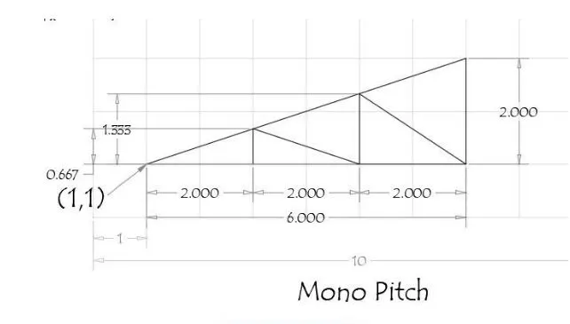
Steps of creating geometry in AutoCAD Software by Absolute coordinate system :
- Type the command " L " for the line and specify the coordinate for Starting point 1 ( 1,1 ) .
- Type the next coordinate of point 2 ( 7,1 ) in the command box .
- Type the next coordinate of point 3 ( 7,3 ) in the command box and then click " close " on the command box .
- Cancel the line command by pressing enter .
- Type the command " L " for the line and specify the coordinate for point 4 ( 3,1 ) .
- Type the next coordinate of point 6 ( 3,1.667 ) in the command box .
- Type the next coordinate of point 5 ( 5,1 ) in the command box .
- Type the next coordinate of point 7 ( 5,2.333 ) in the command box and cancel the line command by pressing enter .
- Type the command " L ' for the line and join point 7 and point 2 and press enter .
RESULT :
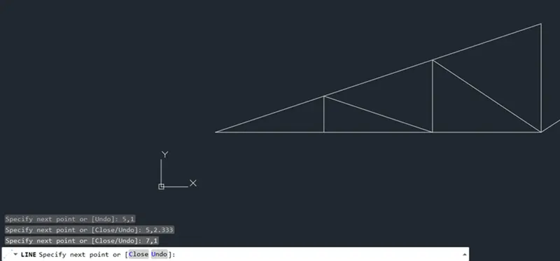
Steps of creating geometry in AutoCAD Software by Relative Rectangular Coordinate System :
- Type the command " L " for the line and specify the coordinate for Starting point 1 ( 1,1 ) .
- Type the next coordinate of point 2 @ 6,0 in the command box .
- Type the next coordinate of point 3 @ 0,2 in the command box .
- Click " close on the command box and cancel the line command by pressing enter .
- Type the command " L " for the line and specify the coordinate for point 4 ( 3,1 ) .
- Type the next coordinate of point 6 @ 0,0.667 in the command box .
- Type the next coordinate of point 5 @ 2 , -0.667 in the command box .
- Type the next coordinate of point 7 @ 0,1.333 in the command box and cancel the line command by pressing enter .
- Type the command " L " for the line and join point 7 and point 2 and press enter .
RESULT :
Steps of creating geometry in AutoCAD Software by Relative Polar coordinate :
- Type the command " L " for the line and specify the coordinate for Starting point 1 ( 1,1 ) .
- Type the next coordinate of point 2 @ 6 < 0 in the command box .
- Type the next coordinate of point 3 @ 2 < 90 in the command box .
- Click " close " on the command box and cancel the line command by pressing enter .
- Type the command " L " for the line and specify the coordinate for point 4 ( 3,1 ) .
- Type the next coordinate of point 6 @ 0.667 < 90 in the command box and cancel the line command enter .
- Type the command " L " for the line and specify the coordinate for point 5 ( 5,1 ) .
- Type the next coordinate of point 7 @ 1.333 < 90 in the command box and cancel the line command b enter .
- Type the command " L " for the line and join point 6 and point 5 and press enter .
- Type the command " L " for the line and join point 7 and point 2 and press enter .
RESULT :
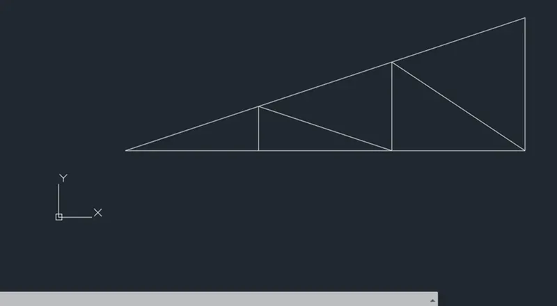
Steps of creating geometry in AutoCAD Software by Direct Distance Entry :
- Type the command " L " for the line and specify the coordinate for Starting point 1 ( 1,1 ) .
- Type the length 6 in command box to + ve x - axis for point 2 .
- Type the length 2 in command box to + ve y - axis for point 3 .
- Click " close " on the command box and cancel the line command by pressing enter .
- Type the command " L " for the line and specify the coordinate for point 4 ( 3,1 ) .
- Type the length 0.667 in command box to + ve y - axis for point 6 and cancel the line command by pressing enter .
- Type the command " L " for the line and specify the coordinate for point 5 ( 5,1 ) .
- Type the length 1.333 in command box to + ve y - axis for point 7 and cancel the line command by pressing enter ,
- Type the command " L " for the line and join point 6 and point 5 and press enter .
- Type the command " L " for the line and join point 7 and point 2 and press enter .
RESULT :