Week 3 Challenge
AIM AND INTRODUCTION :
- To explain how hydrology and geotechnical studies are used in fixing span as per IRC standards and type of bridge.
- To find the scour depth at the pier and abutment location.
- To give a brief about the measures that can be taken to avoid scour at the bridge for the shallow foundation and to draw the section of measures on the downstream and the upstream side.
- To explain about uplift and how it can affect the foundation and different measures that can be taken to avoid uplift.
- Hydrology: Hydrology in the study of bridge design mainly deals with the properties, distribution, and circulation of water on and above the land surface. The primary objective is to determine either the peak discharge or the flood hydrograph, at the highway stream crossings.
- Geotechnical studies: A geotechnical investigation is the gathering of information about the properties of the soil and rocks beneath the ground that are used when designing foundations or any other structures that require earth properties for the design of any structures onsite.
- scouring: the erosion of soil surrounding a bridge foundation, piers and abutment. scouring occurs when water flows around a bridge with high velocity removes sediments around the bridge foundation, leaving behind scour holes, this will lead to failure of the structure.
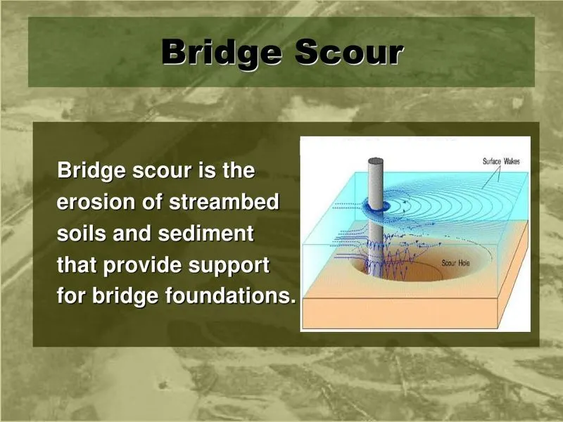
Fig. 1
ELABORATION:
Hydrology
- The hydrological analysis is required for designing all new bridges over waterways, bridge roadway construction and construction over water profile, Typically this should include the following:
- An estimate of peak discharge, catchment area and complete runoff hydrographs.
- Existing and proposed condition water surface profiles for design and check flood conditions.
- Consideration of scour problems.
- The horizontal alignment of a highway at a stream crossing should be considered in selecting the design and location of the waterway opening, as well as the crossing profile, Design should be made to align the highway so that the crossing will be normal to the stream flow direction.
Factors for consideration of Bridge Length:
- The roadway alignment is at a skew to the streambed, and normalizing the alignment would require unsafe or undesirable curves on the approaches to the bridge.
- Embankments may be limited to a certain location due to local soil instability or permitting requirements.
- Bridge costs might be cheaper than embankment costs.
- Matching the highway profile grade line.
- High potential for a meander to migrate, or other channel instabilities.
Geotechnical study:
A geotechnical investigation will include subsurface exploration of a site.
Sometimes, geophysical methods are used to obtain data about sites. Subsurface exploration usually involves soil sampling and laboratory tests of the soil samples retrieved, surface exploration can include geologic mapping, geophysical methods, and photogrammetry.
Foundation soil and rock condition is primary information required for the economic design and construction of any structure.
- Geotechnical aims :
- To find out the nature of the soil and rock deposit.
- Depth and thickness of various soil and rock strata for structure foundation requirement.
- Location of Ground Water Table (GWT)
- In-situ properties by different Subsurface exploration field tests like SPT, DCPT, SCPT, Vane Shear Tests.
- Collection of soil and rock samples for determination of engineering properties in laboratory
- Selection of foundation type and depth
- Geotechnical engineering assessment of Foundation regarding its load-bearing capacity and settlement aspects.
- Stages of geotechnical investigation:
- Soil and groundwater conditions
- Topography, drainage pattern, vegetation
- Condition of existing structures
- Suitability of site for the proposed project
- Types of soil and rock formations from geology
- Presence of natural resources
- Stream pattern, if any
- Seismic activity in the area
IRC: 78-2014 – Standard specifications and code of practice for road bridges
Geotechnical report :
- Geological history and geographical background of the area
- Total scope of work and a plot plan showing locations of all tests
- Brief description of procedure adopted for field and laboratory tests.
- Detailed bore-log/drill-log in the approved format
- Laboratory test results in approved tabular and graphical form with the summary
- True cross-sections/profile of all boreholes and or trial pits
- All geotechnical engineering parameters
- Recommendations on geological and lithological information of the area
- The details of the landslide, if any
- Recommendation for the foundation system of structures
- Recommendations for ground treatment/improvement, foundation and embankment/subgrade treatment in case of weak sub-soil, expansive clay, liquefaction and artesian condition etc.
Scouring And Prevention :
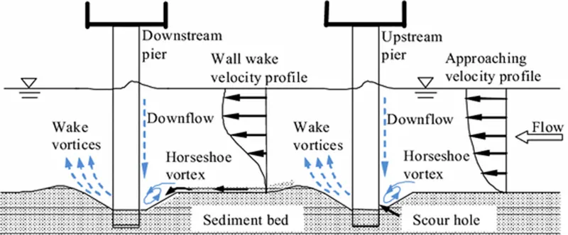
Fig. 2
- Scouring is defined as the erosion or loss of top bed soil around the bridge piers, abutments, spurs etc. due to the water flow currents. Scouring can lead to foundation failure.
- Scour creates holes around piers and reduces the stability of the bridge.
- The flow speed got changed due to the presence of piers or abutments in the flowing direction which reduces the flow area and it makes changes in flow patterns.
- A portion of the separated flow transfers the sediments from around the pier base and it tends to form the hole around the pier and abutment thus scouring takes place.
- Some small structures constructed to the abutments of bridges can help prevent scour, such as the installation of gabions and stone pitching upstream from the foundation and The addition of sheet piles or interlocking prefabricated concrete blocks can prevent erosion.
- Ripraps strengthens the river bed to a certain degree and also slows the water current velocity thus reducing the scouring around the pier
- Reduction of scouring is possible by different approaches using different countermeasures, Collars reduces the scouring to a great extent if it is placed at or below riverbed level.
- Construction of barriers upstream of the bridge piers that consist of the number of piles will reduce scouring depth.
scour depth :
silt factor =3 ,Design discharge = 1000 cumecs
mean scour depth = 1.34 {(Db^2)/Ksf}^1/3
dsm = 1.34{(10*10)/3} ^ 1/3
= 1.34 x 3.21
= 4.31m
For pier, scour depth is 2* dsm, so 4.31 x 2 = 8.62m
Uplift :
- An uplift pressure is any pressure exerted beneath a structure that has the potential to raise the structure higher to a higher level compared to its surroundings.
- water pressure can exert an uplift force on a structure that causes damage to the structure.
- Uplift pressure reduces the effective weight of the structure and reduces the restoring forces on the structure.
- Uplift forces are also seen in some high flood-prone areas where the high water level can result in the uplift of the bridge will sink the structure.
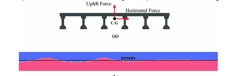
Fig. 3
- The structure must be designed properly to provide greater resistance against uplift forces in order to prevent risks due to water pressure. So, the uplift pressure must be taken into consideration during the design stage.
- The self-weight of the building can be increased by increasing the size of structural members so that the uplifting of the structure can be avoided.
- anchors can be used to counteract uplift forces.
- The piling method is the most effective method to resist Uplift pressure. There are many types of piles available for countering uplift pressure based on soil condition and their necessity on site.
- Uplift Force = ϒwh can be calculated using this formula.
- The factor of safety against uplift pressure = weight of the structure/uplift force
- SELF WEIGHT OF THE STRUCTURE :
section 1 :
Self-weight = area x unit weight. ( multiply by 2 for either sides )
(0.410 x 1.5 x 25 x 2) = 30.75 KN/m3
section 2 :
(2.5 x 0.30 x 25 x 2) = 37.5 KN/m3
section 3 :
(0.30 x 0.5 x 25 x 2) = 7.5 KN/m3
section 4 :
(9.2 x 0.54 x 25 ) = 124.2 KN/m3
Self-weight of the structure = 207.15 KN/m3
UPLIFT :
Uplift force = Yw * h
(3.5 x 10 ) + (4.5 x 10) + (5.5 x 10) + (0.1 x 10 ) = 136 KN/m3
Check for uplift:
FOS= Weight of structure / Uplift force
FOS = 207.15/136 = 1.52
Hence, the structure is safe against the uplift force.
Result :
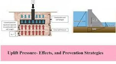
Fig. 4
- Hydrology and geotechnical studies for fixing span as per IRC standards and type of bridge have been explained.
- Check for uplift has been done, we have to be aware of these aspects during the design and need to design the structure for safer condition.
- The base slab or raft foundation can be extended outside the perimeter to increase resistance to uplift. The weight of backfill material on the tied-in foundation increases the weight of the structure against uplift pressure.
- The measures that can be taken to avoid scour at the bridge have been explained above, Construction of barriers upstream of the bridge will reduce scouring.