REVIT_Usage of Elements & Properties_Week 3
Question 1: Use the project file created from Week 2. Use it for this assignment. Based on your layout from week 2, using floor tool under architecture tab and select the floor with appropriate material and thickness using the property browser create a layout in the Ground floor Level. Align the floor plan with grids created from week 2.
Aim: To add the floor layout and set the properties like floor material and thickness.
Procedure:
Step 1: First open the layout created in the last week.
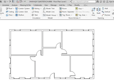
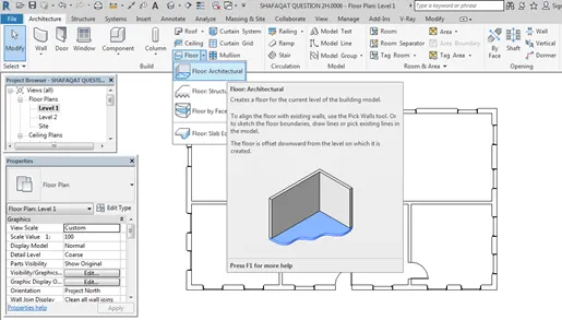
Step 2: Go to Architecture toolbar, click on Floor, click on the Floor Architecture to add the floor into the layout.
Step 3: click on the Pick lines to select the boundary into which floor is to be selected.
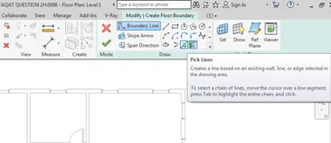
Step 4: click at the boundary of the wall by using pick lines.
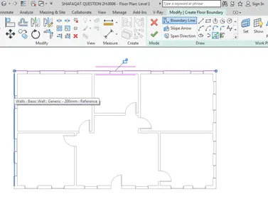
Step 5: after selecting the whole boundary click on the FINISH EDIT MODE to make the changes.
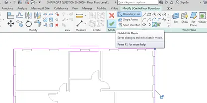
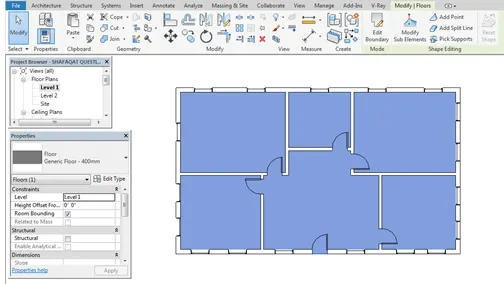
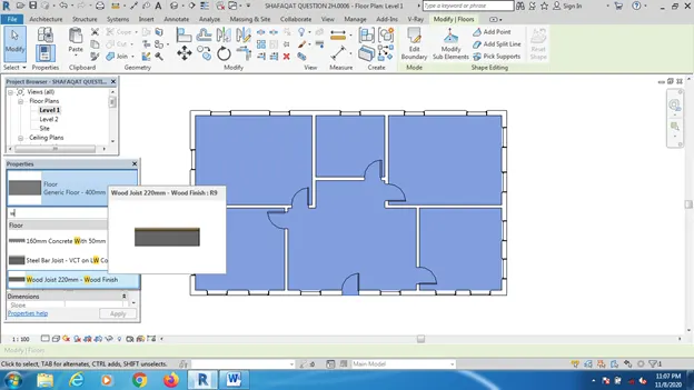
Step 7: go to the floor properties to select the desired type of material and the thickness we want. So we will set the floor material as Wood joist.
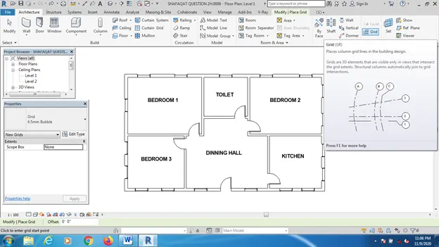
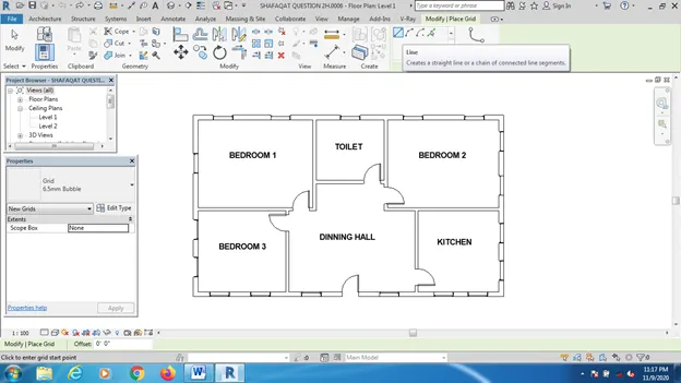
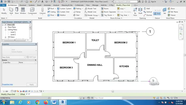
Step 8: We can use grid lines set for the floor plan. Go to Architecture, click on Grid option. Click on pick line to select the boundary. Vertical and horizontal grids can be drawn. For vertical grids give the numbering as A,B,C,D. And for horizontal grids as 1,2,3.
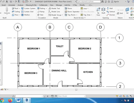
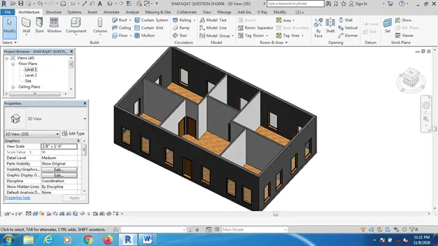
Result: Go to the 3D view which will appear as
Question 2: Add walls based on the floor layout. Pick lines or use the draw tool to modify the boundary of walls. Use the property browser to select appropriate material and thickness for walls. After creating the walls verify using the property browser to see if the top and bottom of the walls are constrained.
- Based on your observation, what is beneficial for connecting walls with associated levels rather than being Unconnected.
b. Which option is convenient for modeling walls, By Height or By Depth?
Aim: To draw the walls based on the layout and make the use of pick lines and property browser to set the properties of the walls.
Procedure:
Step 1: open the given layout made in the previous week.
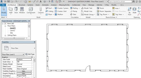
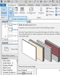
Step 2: Go to the Architecture Toolbar, Click on a Wall option, click on Architecture wall to add a new wall.
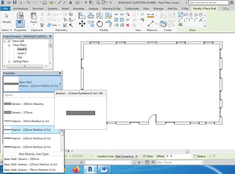
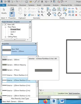
Step 3: Go to the properties browser to set the type of wall and wall thickness. Select the wall type as interior 123mm Partition to add the interior walls.
Step 5: In properties browser set the Base Constraint as Level 1 and Top constraint as Level 2.
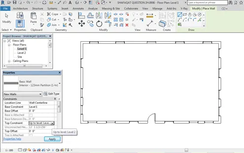
Step 6: Draw the interior walls.
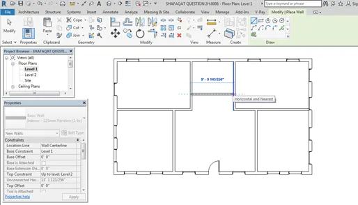
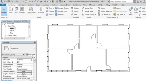
Step 7: Go to Architecture Tab and click on the Door to add the doors into the layout.
Step 8: To change the wall material, select the wall and go to property browser, and click on Edit Type option, click on the edit in structure option, select the structure material as concrete.
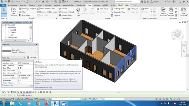
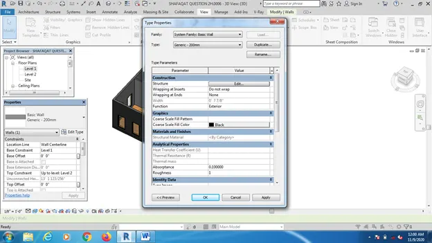
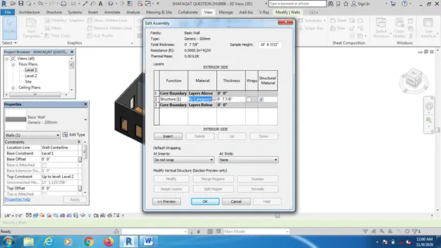
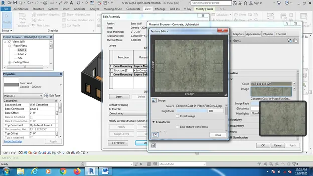
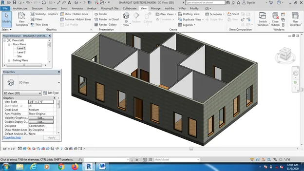
Result: The wall material has change to concrete as seen in the 3D view.
- a) Benefits of using connected walls with the Levels is that if we modify the heights of the level then automatically the height of the corresponding connected wall will change.
- b) From my side, By height option is efficient than by depth for model walls.
Question 3: Copy the model elements ( wall, floor ) modelled to Ground Floor Level and paste it aligned to First Floor Level . Use modify tab to utilize copy and paste options to align elements to a different.
Aim: To use the copy and Paste commands for increment of the different floors.
Procedure:
Step 1: open the layout created in the previous week.
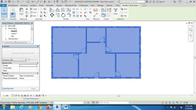
Step 2: select the whole layout, click on the copy To Clipboard option to copy the given ground floor layout.
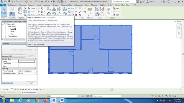
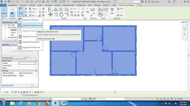
Step 3: Click on the paste option, click on the Aligned to selected Levels option.
Step 4: A popup window comes with the options as Level 1 and Level 2. Choose the Level 2 option which means that the layout that we copied will be pasted at the level 2.
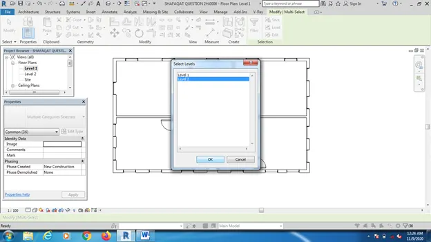
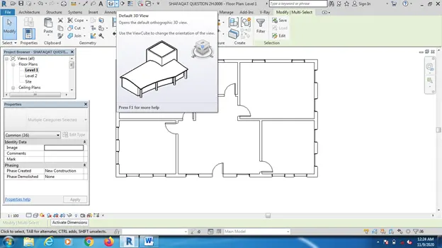
Result: The first floor has been created by using the copy and paste option. The 3D view is given as
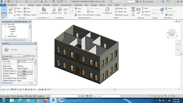
Question 4: Use interior partition walls to create separate rooms within your residential unit. The model must include the following rooms
- Living Room/ Drawing Room ( 15’ X 18’)
b. Dining Room (9’ X 11’)
c. Bed Room ( 9’ X 12’ and 15’ X 11’)
d. Rest Room ( 10’ X 12’ )
e. Kitchen (8’ X 10’)
The above are for examples. You can use them or use your measured entities to create your model based on your layout. You may include entry walkway, Patios or Guest
rooms based on your creativity and purpose of modeling. Convert units if you are using metric system
Aim: Draw the interior partition walls for making separate rooms with the dimensions required.
Procedure:
Step 1:First create a new architectural project.
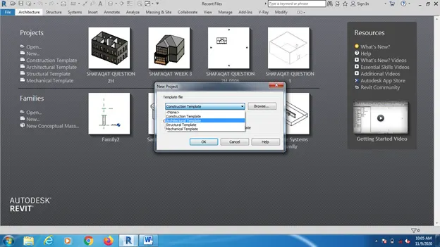
Step 2: Go to Architecture Toolbar, click on the Wall, Wall Architecture tab to create the walls of the layout.
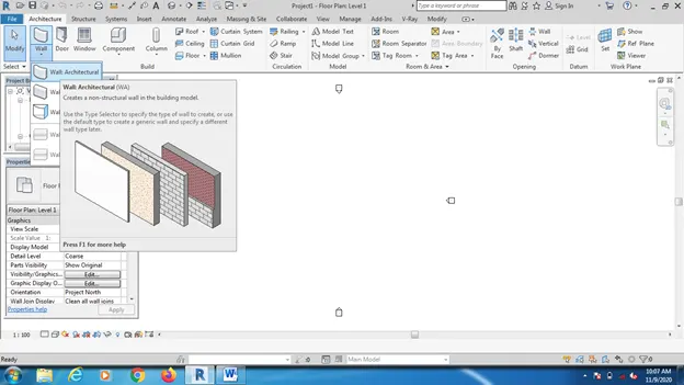
Step 3: Go to the property browser to select the type of wall and also change the thickness and height.
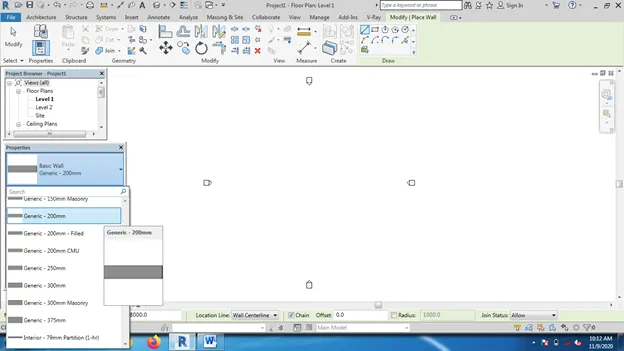
Step 4: Set the wall between the level 1 and level 2 as required with the help of base and top constraints. Base constraint as Level 1(Ground Floor) and top constraint as Level 2.
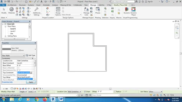
Step 5: GO to the 3d view.
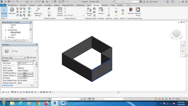
Step 6: Go to the Architecture Toolbar, Click on the wall Architecture, Go to the Properties to set the wall type as Interior Partition Wall. Or also go to edit option to set our own design and material.
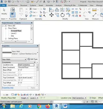
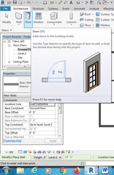
Step 7: Click on the Door option to add the doors into the layout. And also go to the properties option to set the door material and the dimensions of the door.
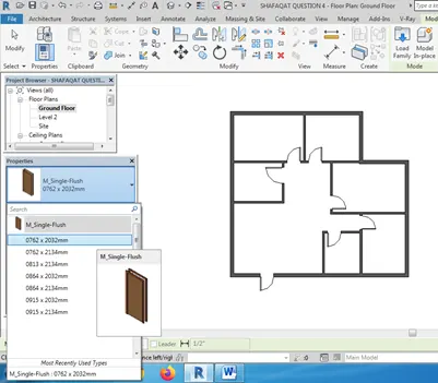
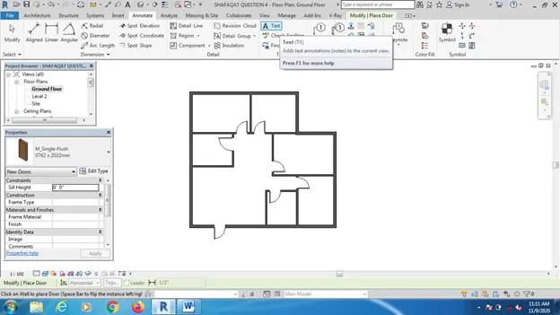
Step 8: Go to Annotate tab, click on the Text option and set the text for different rooms to identify them.
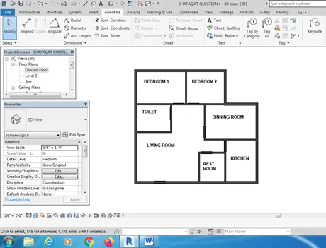
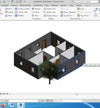
Result : The given layout in the 3D view looks as
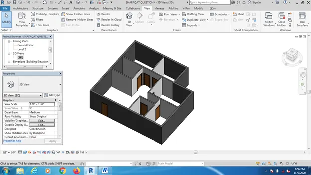
Question 5: Based on week 2 assignment, the components to be included in a residential unit were inserted to the Revit file. Place these components in appropriate locations to add details to your residential model
- Place Doors and windows in the wall at appropriate locations
b. The Living Room must include furniture set, couch table and TV desk and shelf cabinets
c. The Dining Room must include a table and chairs serving the purpose of eating
d. Bed Room must include a bed set, shelf, lighting and individual study desk and chair
e. Rest room should include bath tub and plumbing fixtures discussed in class
f. Kitchen should include countertops, gas stove cabinet and shelves to store food items
g. The wash/storage room can include washing machines and shelves to store clothes
All the components are available in Revit Library. Use them to place at appropriate locations to add details to your model. Use 3D navigation to check the model and its authenticity on a real time basis to verify the model
Aim: To add different components like doors, windows, Tables, Chairs, Beds etc. into the building layout.
Procedure:
Step 1: first open the layout created in the last week which consists of the doors .
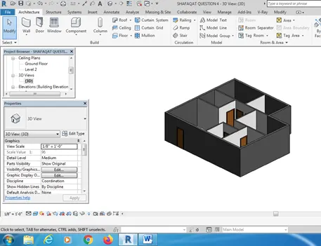
Step 2: To add windows into the layout, go to Architecture Tab, click on windows. Go to the properties browser to select the dimensions and the type of window.
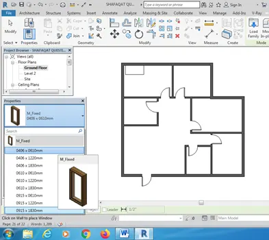
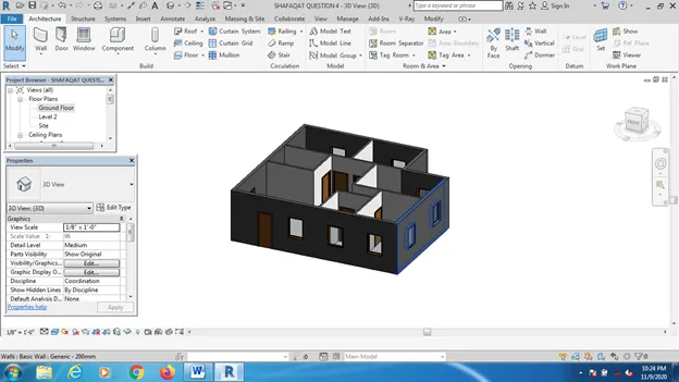
Step 3: to add the Components like Table, go to the Architecture, go to Components option, select Place a Component
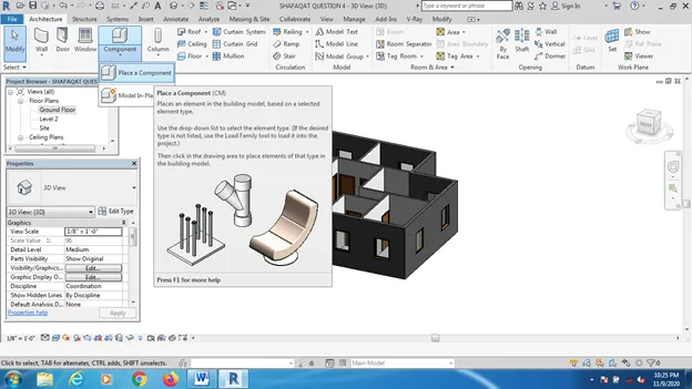
Go to the properties browser to select the table as M_Desk.
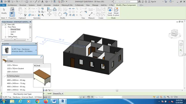
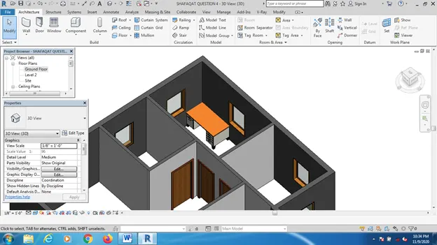
Step 4: In the same manner we can add different components like beds, chairs into the system.
Step 5: Or we can use Families to insert the different components.
Step 6: Go to the Camera view to view the inside of the bulding.
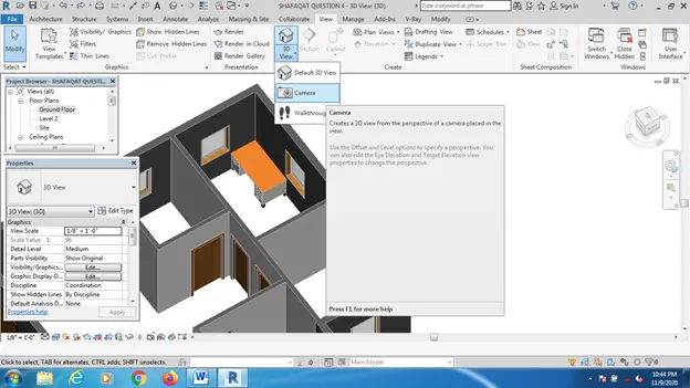
Select the direction of the camera which we want to view.
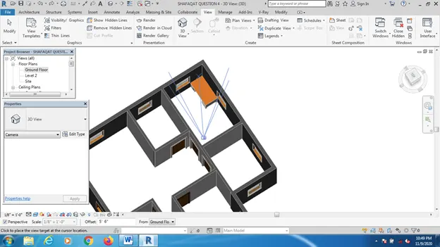
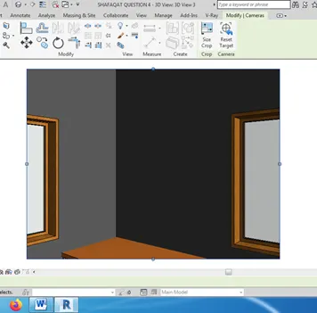
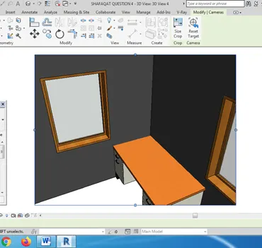
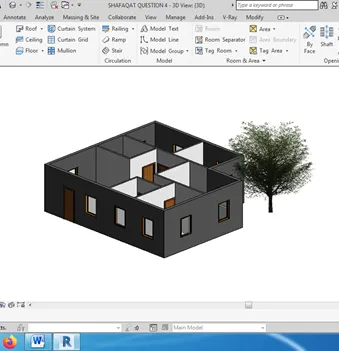
Step 7: Also we can add tree around the building by using the component option.
IN MY SYSTEM FAMILIES IS NOT AVAILABLE, SO I AM UNABLE TO ADD CHAIRS, BEDS AND OTHER FURNITURES.
Result: 3D view as