Week 3:- BiW Fixture Design Methodologies Challenges
1. What is Design Methodology?
A design methodology is a set of procedure that we must adhere to when creating a design.
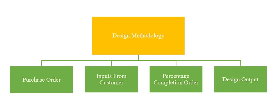
- Purchase Order - After receiving a purchase order from the customer, we begin creating. In essence, it is a signal to begin designing a specific fixture.
- Customer input - Before we begin the actual design work, the customer provides us with the fixture's requirements or specifications. Therefore, we must design fixtures considering every aspect of the customer.
- Percentage completion criteria - We must develop a timeline or time plan known as percentage completion criteria in order to finish design on time. This includes a list of all design-related tasks and the amount of time needed to perform them, such as concept design, final design, and two-dimensional drawings of every unit in the fixture.
- Design output - The design output is a large collection of data that includes, among other things, BOM, gas-cut or laser-cut DWG files, VMC IGS files, STEP files, and 3D & 2D documents. These data must be provided to our customer as part of the design result.
2. What are the inputs required from the customer to start designing a Fixture?
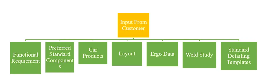
- Function Requirement - In general, this refers to the reason behind the design of a fixture, such as an inspection, welding, gluing, or riveting fixture.
- Preferred standard components - In order to save time, money, and efforts when developing and manufacturing non-standard components, we must utilize standard components as much as possible while constructing fixtures.
- Car product - PLP (Principle Locating Points) of fixture, geometric tolerance, read files and 3D are all included.
- Layout - Layout is essentially the management of space, which aids in the comprehension of the assembly line's overall work process.
- Ergo data - All business have standard ergo data, which they give to fixture designers so that they can design fixtures taking those aspects into consideration. For example, the height of the fixture is chosen based on how comfortable it is to work on. Therefore, we must build a fixture with safety, ease of use, and fool proof design in mind.
- Weld design - Based on the customer's specification of the type of welding (spot or seam) needed to attach components, we must design the fixture.
- Standard detailing templet - We can use the standard detailing templet that the customer provides us with to detail or dimension components in accordance with it.
3. What is the input we get from "Car Products"?
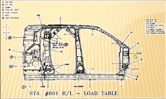
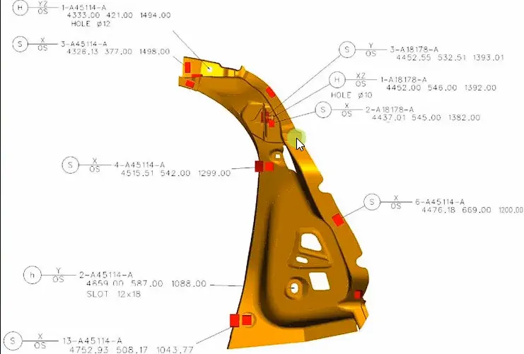
- GD&T - Geometric Dimensional and Tolerance are the acronyms for GD&T. The automobile package includes GD&T for every part, along with information on where to get clamps, slides, rests, and pins. The image below illustrates how GD&T are applied to specific part.
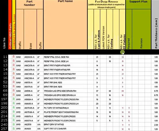
- Part list - Describes the components and method of assembly. Every component in the assembly has a unique part number, and the part list includes all of the part names for every component. This makes it easier to identify every component as you go through the assembly process.
- CAD part files of car parts - When designing fixtures, 3D CAD files of the parts are required.
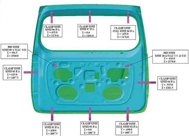
- Clamp plan - This is one of the most crucial pieces of information to have when building a fixture since it indicates where the clamps will be placed and on which component.
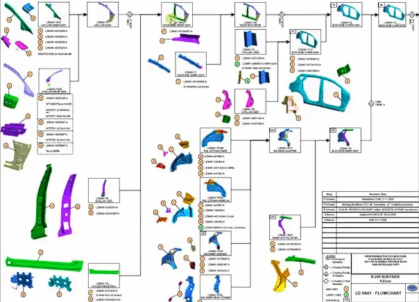
- Product assembly process sheet - This document outlines the steps or order in which components are assembled.
4. What is the Clamp plan?
A Clamp is a type of fastener that applies internal pressure to hold or secure things firmly together to prevent movement or separation.
Essential requirements of clamps
All clamps must fulfil four essential requirements. They are,
- The work piece needs to be kept rigid during the procedure.
- The clamping device must have a quick acting mechanism in order to minimize the amount of time needed to load or unload the tool.
- The clamping needs to be positive when it is subjected to chatter, vibration or intense pressure.
- The work item cannot be harmed by the clamp
Clamp Plan
Clamp plan is a crucial component of automotive products, it tells us just where to insert those clamping units, which are specific pin units.
- The location of the specific clamp or pin, as indicated by these data, should never be altered.
- We can make minor adjustments to our design here and there, but we shouldn't alter the input design data pertaining to the pin or clamp positions.
- There are clamp and pin units as well as further detail in the clamp plan. Additionally, it provides the precise location of Y and Z coordinates for designing. All you have to do is enter these coordinates, and the design process can begin.
- If all three coordinates, the complete diameter, and all other necessary information are provided for designing the future design phase, and occasionally the ministry as well. It so occurs that an additional thought position is provided, likewise in close proximity to the clamp or clamp site. Thus, constantly check to see if the clamp position has been altered.
- We should never adjust the clamp or vent positions without first asking. Thus, always be flexible in these circumstances. Therefore, before making any changes to the clamp, it is necessary to clarify again in case the tool or department sustain harm.
5. What is the purpose of a layout?
The layout's goal is to comprehend details such as the locations of fixtures and robots, the area that each robot covers when working, which fixtures are designated for the robots to complete specific tasks, etc. In order to grasp the process, the layout displays the complete assembly design.
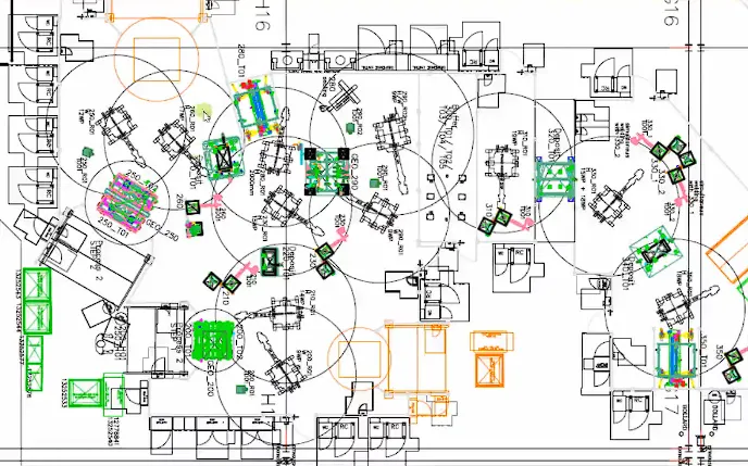
The robot's swept area, represented by the circle surrounding it, indicates how reachable the robot is, especially when paired with the confine circle. The layout gives information about the parts flow, robot stations, station pitch, sub assembly links, tool changers and tip dressers, accessories, plat form height and the sequence and height of loading and unloading. The layout document will tell you where each fixture is located and where the robots will be working. The circle surrounding the robot on the layout sheet is referred to as the robot's trapped area. This essentially sums up the robot's reachability, which is limited to a certain circle.
- Flow of parts - This diagram illustrates how components move from one station to another once a process is finished on an assembly line or shop floor.
- Station pitch - Station pitch is the separation between two stations. The arrangement demonstrates the little space between the two stations.
- Robot stations - This illustrates the layout-based placement of the robots and their accessories
- Sub assembly link - This is just the connection between the main assembly line and the assembly fixtures. It illustrates the connection between the main assembly line and the sub assembly fixtures.
Understanding the assembly line's overall strategy is the layout's primary goal. The layout that provides the aforementioned details, such as part flow, station pitch, robot stations, etc., is utilized to comprehend how robots operate, which fixtures are assigned to them, how much space is available, etc. The designers can create concept sketches of fixtures without any assembly line conflicts by taking the layout into consideration. Obtaining knowledge regarding space constraints is one of the primary goals since it aids in the development of robotic cells that operate without interference.
6. What is Ergo data?
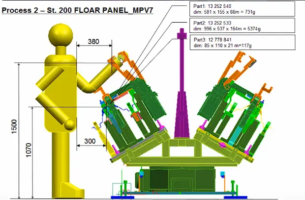
Every business has standard ergo data, which they give to fixture designers so that they can build fixtures taking those factors into consideration. For example, the height of the fixture is chosen based on how comfortable it is to work on. Therefore, we must build a fixture with safety, ease of use, and fool proof design in consideration. Ergo data is utilized to improve productivity, human comfort, safety, and a reduction in human mistake.
Let's examine several samples to better grasp what ergo data is. The base unit's height is determined by the worker's comfort level, posture, and height. One of the ergo statistic is height, and there are other data like this one that are determined by taking safety and human comfort into account.
7. What do you understand by weld study?
All weld study entails are a study of the welding gun we will employ in the welding fixture and the welding location. Studying welding gun details, weld matrix, weld point, geo weld points, re-spot weld points and other things are all included. The following points are studied in a welding study,
- Weld gun details - We will examine which kind of gun is appropriate for a given fixture, as well as where and how to use the chosen gun.
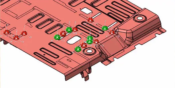
- Geo weld points - The proposed location for the geo welds are indicated in the geo fixture. These welds will ascertain the panel positions according on the information provided in the drawing. In the weld study inputs provided by the customers, the geo weld points are represented by a red sphere.
- Re-spot weld points - The re-spot tool is used to plan the re-spot weld locations. The strength and rigidity of the panel and its components will be decided by these welds. In the weld study inputs provided by the clients, the re-spot weld locations are shown as green spheres.
8. What are the criteria for percentage completion in the designing stage? Explain it in detail.
When developing and dispatching welding equipment, the percentage completion criteria is adhered to. The project is tracked using this percentage completion criteria to see if it is completed by the deadline that was promised to the customer when the projects were turned over to them. Additionally, it aids in project stage identification, allowing us to know how much of a project is finished and what steps are still outstanding, all of which contribute to project completion on schedule. To find the percentage of the task completed, the percentage completion criteria is broken down into four parts.
- Input & concept design
The project's percentage completion criteria will range from 0% to 25% if it is in the input and concept design stage. The project will proceed to concept approval and simulation check, which is the second step in the percentage completion criteria, after input and concept design are finished. - Concept approval & simulation check
The project's percentage completion requirement will fall between 25% and 40% if it is in the concept approval and simulation check stages. The project will proceed to design freezing and detailing, which is the third step in the percentage completion criteria, following the conclusion of concept approval and simulation check. - Design freezing & detailing
The project's percentage completion requirements will range from 40% to 85% if it is at the design freeze, and detail stage. The project will proceed to the fourth and final stage in the percentage completion criteria, check and final dispatch, following the completion of design freezing and detailing. - Check and final dispatch
The project's percentage completion criteria will fall between 85% and 100% if it is in the check and final dispatch stage. Following the check, the project will ultimately be successfully delivered to the client.
9. Brief about "output" in design?
In any industry, including BIW fixture design. We don't just design a component and send the customer the CAD file; you also need to send a ton of documents, including 2D and 3D drawings, which are for the detailing phase, as well as other information like bill of materials and boom, as well as other documents about this specific component and its standards.
The basic output are 3D models and 2D drawing of fixture. Output are classified as below,
- Unitized tools
Two different kinds of drawing sheets are needed for unitized tool testing, a key sheet and a layout sheet. Thus, fixtures and tools are examples of unitized tools. Therefore, precisely where are many units placed. For instance, everything needed for the pin unit, clamp unit, rest unit, and panel is included in the complete assembly welding fixtures.
Key sheet - An index of the tool base's units and their locations. It will feature a numbered balloon drawing that lists the units along with an orthogonal view of the fittings.
Layout sheet - An intricate drawing of each unit that shows every part of it. Key sheets are not required for the non-unitized tool. The drawing can have all the details needed on a layout sheet because it can stand alone.
The key sheet will therefore show you the precise placement and location of that specific instrument on the tool base. Essentially, it is an index of units and locations on the tool base. And where exactly he is in a given location. - Non-unitized tools
Tools that are self-contained and fully detailed on a layout sheet. Non-unitized tools are essentially those that are not part of a set; Stands and tool changers are two examples of non-unitized tools that can be used to complete the layout sheet and the component's full documentation without the requirement for a key sheet. Thus, these are known to be non-unitized tools.
The design output should compile following points,
- Whenever feasible, use approved standard components.
- The most basic and economical design is required.
- The design needs to adhere to all current ergonomic and safety regulation.
- The product must be designed to be handled carefully and without damage.
- Each design must have sufficient error proofing measures, such as proximity switched, rough locators, etc.
- The moving elements have to be as light as possible while still being as strong as possible.
- Simple and sturdy frames and structures are required.
- Approval for design and accessibility for regular upkeep and servicing.
- Motion control needs to be considering for any moving machinery.
- The designer is in charge of verifying clamps and welding guns.
10. What do you understand by structuring a design tree? How does it reduce errors during the design process?
The process of organizing a design tree entails naming all of the assemblies and pieces according to a certain standard. The criteria used by various clients to organize a design tree vary. It is a crucial procedure that aids in determining which project, tool, or unit a given part or assembly belongs to. This aids in preventing mistakes from occurring during the design, production, assembly, inspection, etc. It will be difficult to comprehend the design and there may be a high chance pf error if the parts or assemblies are not labelled correctly or the design tree is not organized correctly. The designation of a fixture, unit, or part indicates to which project, zone, or assembly it belongs. It can assist us in determining the number of identical or different sorts of goods being used in the assembly. The base unit will be the initial unit designed when creating a fixture. Standard parts should come last in a structural tree, with all manufacturing parts placed first. A structure tree makes it easier to analyse or comprehend the components of an assembly.
Structure of a design tree,
- The naming of the assemblies, parts, units have certain standard procedures.
- For example, P001_Z03_ST09_00_00_R
where,
P001 - Project name
Z03 - Zone name
ST09 - Station name
00 - Unit name
00 - part number.
R or L -Right / Left hand side of the panel. - In some cases, for example,
panel name will be represented
JG3 - This represents Jig name (represented instead / in the place of station name).
11. What are Units? Mention 5 types of Units.
An assembly with a specified purpose, such as clamping, positioning, or resting, is all that a unit is. A number of units are present in the fixture. The two main purpose of a fixture's design, according to the 3-2-1 principle of location, are to clamp and locate the component for which it is intended. The chart below represents the different units of fixture.
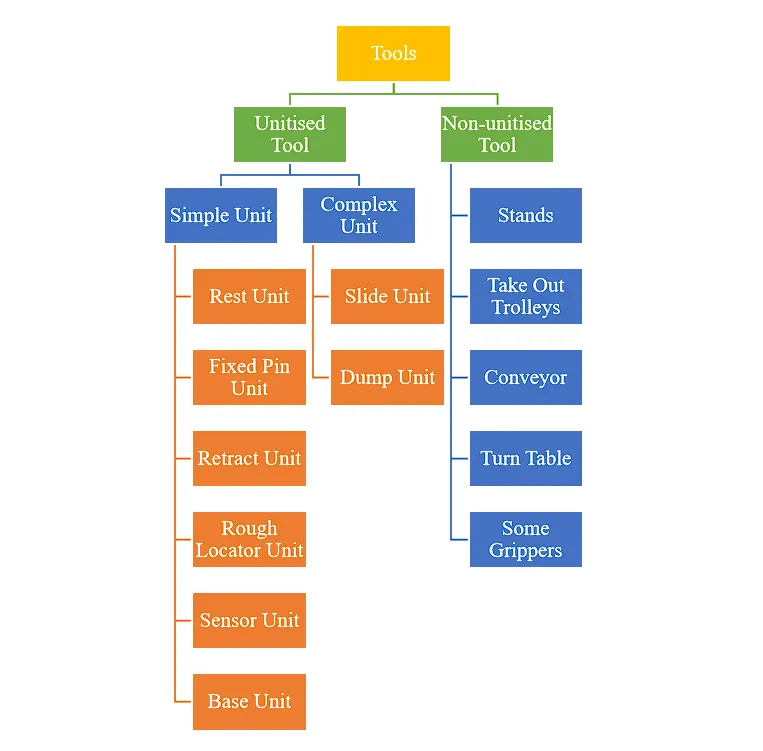
Units are classified into two, they are,
- Simple unit - In a simple welding fixture, the combination of these different units will be seen,
1. Rest unit
2. Fixed pin unit
3. Retract pin unit
4. Rough locator unit
5. Sensor unit
6. Base unit - complex unit - In a complex welding fixture, in addition with some of the simple units these complex units will be seen,
1. Slide unit
2. Dump unit
Five type of units,
- Base unit - A base unit is intended to hold other tool units, such as clamp, pin, rest, and other units. It can also hold other components that are required for a tool, such as trunk cable path and pneumatic valve box.
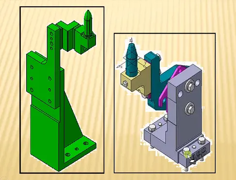
- Fixed pin unit - A fixed pin device uses pins to locate the automobile panel. Fixed pin unit consist of pin, pin retainers, shims, blocks, blades, and riser. To keep the pin firmly in place, use a pin retainer. The locating pins are usually used to precisely locate a body part so that a welding procedure may be carried out. A collection of properly positioned locating pins constrains the body part; hence, entire constraint by locating pin should always be fully limited to prevent any movement.
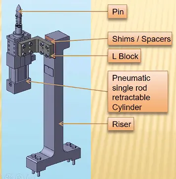
- Retract pin unit - The retractable pin unit is made to use pins find the automobile panel, nevertheless, the retractable pneumatic cylinder will hold the full pin package. In contrast to fixed pin units, retractable pin units can be retracted up to a predetermined distance and moved up and down. After welding, it is mostly utilized to unload the complex panel.
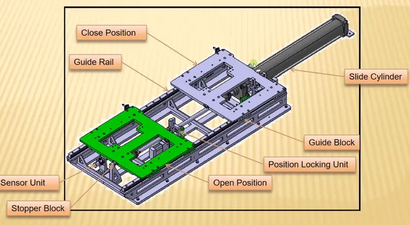
- Slide unit - The majority of complex fixtures with sliding mechanisms contain slide units. When there are space restrictions, this kind of equipment is utilized. The components of slide unit generally consist of a guide block, guide rail, position lock unit, stopper block and sensors.
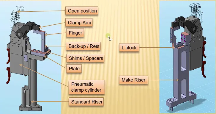
- Clamping unit - A clamp unit uses a pneumatic clamp cylinder to clamp or hold an automobile panel using NC blocks or mylars. After locating the pin unit, the clamping unit is utilized to clamp the item that has to be welded. Clamp arms and pneumatic cylinders are used to accomplish clamping. A clamping unit's general components include a clamping arm, finger, rest, shims, standard riser, and pneumatic cylinder.
12. Describe Fixed Pin units & their purpose.
A fixed pin device uses pins to locate the automobile panel. Fixed pin unit consist of pin, pin retainers, shims, blocks, blades, and riser. To keep the pin firmly in place, use a pin retainer. The locating pins are usually used to precisely locate a body part so that a welding procedure may be carried out. A collection of properly positioned locating pins constrains the body part; hence, entire constraint by locating pin should always be fully limited to prevent any movement.
Purpose of Fixed pin unit,
According to 3-2-1 principle, the introduction of two pins aids in the arrest of two of the six degree of freedom (two radial and four axial movements), while the installation of a minimum of three supports arrests the remaining six degrees of freedom. The purpose of the locating pins is usually to precisely place a body part so that a welding operation may be carried out. A collection of properly positioned locating pins constrains the body part; hence, entire constraint by locating pin should always be fully limited to prevent any movement.
13. What are the different parts of a fixed units?
A fixed pin unit consists of pin, pin retainers, shims, blocks, blades, and riser.
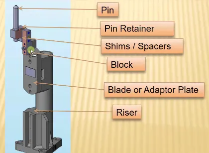
- Pins - It serves the purpose of locating the panel. The locating pins are usually used to precisely locate a body part so that a welding procedure may be carried out. A collection of properly positioned locating pins constrains the body part; hence, entire constraint by locating pin should always be fully limited to prevent any movement. Locating pins come in dozens of styles that can be used in a design. Stepped pins, which come in tiny or big heads, are among the most widely used pins. The round pins and diamond pins are also used.
- Pin retainers - The locating pins are held firmly in place by pin retainers. Pin retainers serve as both a resting spot and a means of holding pins in place. A counter hole is bored to accommodate the pin.
- Shims - Shims are generally employed to fill in tiny gaps or gaps between items. They are typically thin, tapered, or wedged pieces of material. Shims are usually employed to offer a flat surface, modify for better fit, or give support. Shims can also be employed as spacers to close up gaps left by worn parts. Shims are the tiny components that have thickness of 0.1, 0.2, 0.5, 1.0 and so forth. These will make up for the tolerance to stacking, which shows at the mylars. Tolerances are applied to every component of the fixture. The mylars will either raise or lower from their defined position as a result of this tolerance. Shims are used to modify the mylars in order to get the desired position. Above the mylars, there will be extra shifts to allow for tolerance adjustments.
- Riser - A riser is a manufacturing component that is used to raise or heighten fixture assemblies. The riser will be fastened to the blade at one end. L type and square type are the two types of risers.
- Blade - The plates that are fastened to the riser are called blades. Additionally, blades are mounted or affixed to cylinders, arms, etc.
14. What is the purpose of making a Rest unit & describe its parts?
The purpose of a rest unit is to support a car panel using NC blocks / mylars / rest. Only the component is rested; no force or upper clamp is used there. Because there are fewer pieces to build and the only function is to rest the car panel, it is the easiest unit to design. Owing to its simplicity, the remaining unit is integrated with other units to lower the project's total cost.
It can be used in conjunction with a clamp device to both clamp and rest an automobile panel. It can be used in conjunction with a locating equipment to both locate and rest the automobile panel. To cut cost, locating, clamping, and rest units can all be merged into one unit. It is not attached to any cylinder. It features a riser, blade, and rest mylar, and the various rest unit components are below. Retractable support units, numerous support units, and simple support units are other categories for rest units.
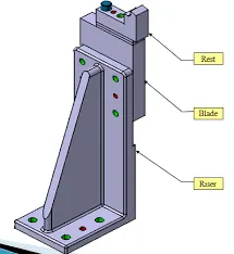
Parts of rest unit,
The parts of rest unit are as follows,
- NC block / mylars
The components that keep the panel together from top to bottom are mylars. It's a jaw type, meaning that it won't move while welding. Another name for it is fingers. It prevents the part from deforming as a result of welding forces. There are two varieties of mylars,
1. Clamping mylars
2. Resting mylars.
Only resting mylars can be seen in rest unit. The panel which rests on the part is known as resting mylars - Risers
A riser is a manufacturing component that raises or heightens fixture assemblies. The riser will have one end fastened to the base unit and the other to the blade. Riser can be of two types,
1. L type riser - L shaped riser is made via welding. The wedge-shaped structure known as the stiffener is utilised as a support and to withstand load. The stiffener will be inserted at the centre for support.
2. Square tube riser - Square tube risers are of frame type. - Blades
The plates that are fastened to the riser are called blades. Additionally, blades are mounted or affixed to cylinders, arms, etc. - shims
A shims is a thin piece of material, usually tapered or wedged, that is used to fill in tiny gaps and spaces between items. Shims are usually utilised to offer a flat surface, modify for better fit, or offer support. Shims can also be employed as spacers to close up gaps left by worn parts.
15. What are the basic fundamentals to design a Sensor unit?
A sensor is a tool used to measure or identify physical attributes. The unit, known as the unit sensor, is designed to use electrical sensors to sense the part or vehicle panel. Next, the sensor's output signal is sent to a PLC (Programmable Logic Control) for additional processing. Many kinds of sensors exist, including laser and proximity sensors.
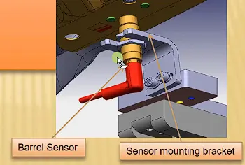
Basic fundamentals to design a sensor unit,
- It is important to detect each and every loose panel that is being welded in a tool
- Depending on the size of the panel, one or two sensors should feel it; it is preferable for the sensors to be placed diagonally opposite each other.
- In general, each sensor should be installed in a three-dimensional adjustable manner.
- We ought to make every effort to reduce the sensor's size.
- OMRON, IFM, Pepperl Fuchs, Sick and others are a few of the leading sensor manufacturers.
16. What is a Rough locator unit & What are the basic fundamentals to consider while designing it?
Rough locators are parts that are used to help the operator load components into the fixture by helping them locate the components accurately.
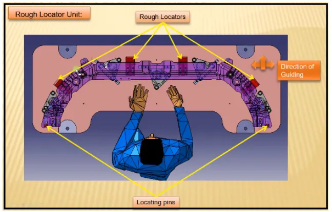
Basic fundamentals to consider while designing,
- A rough locator that must guide should be positioned at the automobile panel's edges.
- The rough locator needs to be positioned with a minimum of 2 to 5mm between it and the automobile components edge, at the same angle.
- In general, rough locators should lead the panels in the direction of pin assembly.
- Before 10mm to 15mm, or the beginning of the pin engagement, rough locators should begin guiding the panel.
- As seen in the accompanying image, rough locators should be built with an entry angle for automobile part entry.
- In general, rough locators ought to be made with two mounting slots for simple adjustment.
- The slots ought to face the direction of the vehicle's part guidance.
17. What is a Base unit and describe its parts?
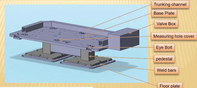
The purpose of a base unit is to support all other tool units, such as clamp, pin, rest, and so forth. Pneumatic valve boxes and trunk cable paths can also be put on top of base units.
Parts of base unit,
The parts of base units are as follows,
- Valve box
In essence, a valve box is a box that provides air to each pneumatic cylinder that is assembled within the fixture. Air is collected from the pneumatic cylinders and sent to the valve box using a single solenoid valve. - Trunking channel
One type of cable duct that aids in guiding and shielding the cabling and tubes used in fixtures is the trunking channel. - Measuring hole cover
The coordinate points are inscribed on the measurement hole cover. The location and placement of the specific units are indicated by the hole that mentions the coordinates. The measurement hole facilitates QC and CMM inspections. - Eye bolt
A bolt having a loop at one end is called an eye bolt. They serve the purpose of securely fastening a securing eye to a structure so that cables or ropes can be attached to it for lifting. When moving, the eyebolt is utilized to fracture or raise the base unit. - Pedestal and weld bar
The complete base unit will be put on a pedestal, which resembles a stand. - Floor plates
The entire base is mounted to the floor using floor plates. It also aids in achieving the fixture's flatness.
18. What is a Dump unit and What are its functions?
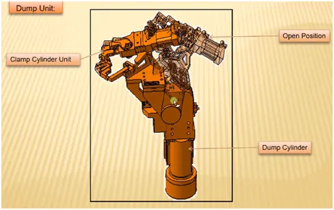
If you are under any constraints, you assemble the components in the dump unit. This is where the clamp unit, pin unit, and panel assembly will take place. Therefore, you cannot assemble in a typical manner. If you have a specific constraint.
Various uses for dump units. It has an intricate design and a dump cylinder. It is made up of a dump cylinder that is used to clamp and unclamp automobile panels. Multiple cylinders can be used in a dump unit to carry out this function.
The assembly holding the clamp mylars and pins is dumped by the first cylinder, after which this assembly completes the necessary task. We need to ensure that this unit allows us to remove the panel when it is in the open position.
19. What is a Slide unit? Mention where Slide units are commonly used.
The majority of complex fixtures with sliding mechanisms contain slide units. When there are space restrictions, this kind of equipment is utilized. The components of slide unit generally consist of a guide block, guide rail, position lock unit, stopper block and sensors.
Slide units are commonly used in,
- Slide units are typically found in intricate fixtures that require a sliding mechanism.
- This kind of device is utilized when there are spatial restrictions while placing the panel
- Application of slides for welding will be simple.
- By using a sliding unit to move the weld gun from one weld location to another weld place rather than a welding robot, the cost of the robot can be reduced.