Week 3:- BiW Fixture Design Methodologies Challenges
Q-19) What is a Slide unit? Mention where Slide units are commonly used.
A-19)
Slide units are further classified
- Manual Slides
- Hydraulic slides
- CNC slides
Slides are positioning units which are used to position the car part or panel units, weldguns, robot for further operation.
Slides may be classified as
- Hardened guide way
- LM guide way
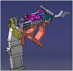
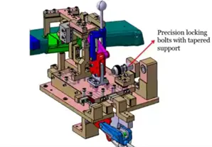
Fundamental of Slide Unit
- Cyclinders and LM guides to be validated for load and stroke.
- LM guide rail length should be standard and should be more than the actual stroke.
- Master guideway should be constrained and the subsidary guideway to be free.
- Slide to clamped in the working position.
- The LM rail should always be covered to protect against weld spatter and dust by bellow or sheet metal cover.
- The design should be checked for screw accessibility, ease of assembly, machinability of parts.
- The LM guide & rails are intergral assemblies and should not be seperated at any costs.
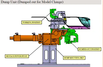
Q-18) What is a Dump Unit and what are its functions?
A-18)
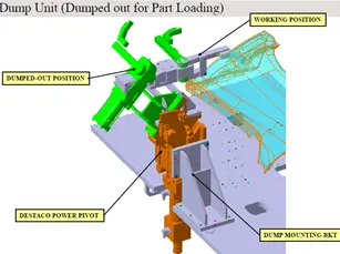
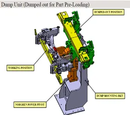
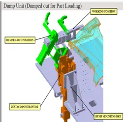
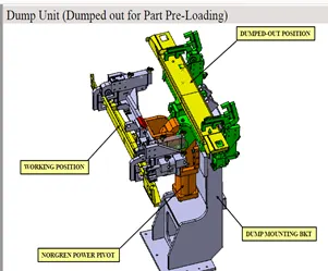
Dump unit is found in complex fixtures.
Dump unit consists of dump cyclinders to perform clamping and unclamping.
Functions – it plays a vital role when there is a geometrical constraint while placing a panel.
Q-17) What is a Base unit and describe it's parts?
A-17) Base unit is the unit used to mount all the other units like clamp unit, pin unit, rest unit
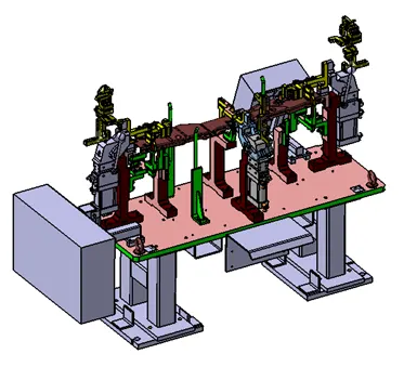
Parts of base unit-
- Valve Box
- Trunking channel
- Measuring hole cover
- Eye bolt
- Pedestal
- Floor Plates
- Valve Box – Valve box consists of one solonoid valve with one inlet and one outlet. The outlet in solonoid valve is used to supply the air to the pneumatic cyclinders from valve box.
- Trunking channel – Trunking channel is kind of cable duct, which helps to guide and protect the wirings/ tubes used in fixtures.
- Measuring hole cover – In the measuring hole cover the co-odrinates are engraved on it. The measuring hole helps in CMM inspection and QC inspection..
- Eye Bolt – An eye bolt is bolt with a loop at one end. They are used to firmly attached a securing eye to a structure so that the ropes or cables maybe tied to it for lifting purpose.
Q-16) What is a Rough locator unit & what are the basic fundamentals to consider while designing it?
A-16) Rough locator unit is a unit designed to guide the operator to locate the car panel on the pins accordingly. A rough locator can be of standard parts
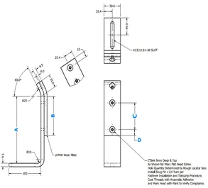
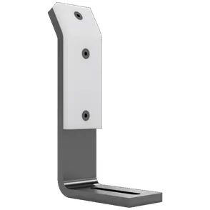
- Rough locators should be placed at the edges of the car panel.
- Rough locators should guide the panels in pin assembly direction in general.
- Rough locators should be designed with the entry angle for car part entry
- The slots should be in the diretion of car part guiding.
Q15) What are the basic fundamentals to design a Sensor unit?
A-15)
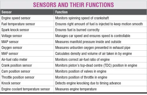
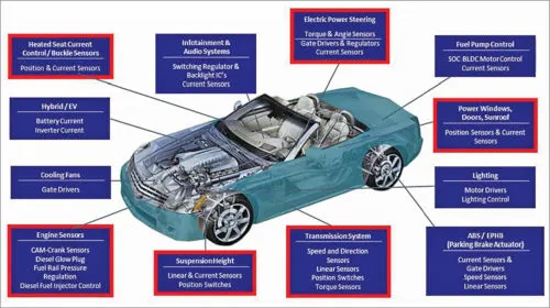
Sensors are the components of the system that provide the inputs that enable the computer (ECM) to carry out the operations that make the system function correctly. In the case of vehicle sensors it is usually a voltage that is represented by a code at the computer’s processor. If this voltage is incorrect the processor will probably take it as an invalid input and record a fault
Types of Sensors used
- Mass air flow (MAF) rate
- Exhaust gas oxygen concentration (possibly heated)
- Throttle plate angular position
- Crankshaft angular position/RPM
- Coolant temperature
- Intake air temperature
- Manifold absolute pressure (MAP)
- Differential exhaust gas pressure
Q-14) What is the purpose of making a Rest unit & describe its parts?
A-14)
Purpose of making a rest unit
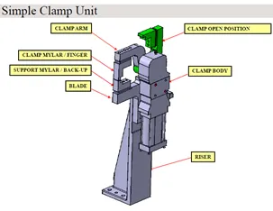
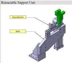
Rest unit is a unit designed for the purpose to rest/ support the car panel using NC block or mylars
The mylars in rest unit is known as resting mylars
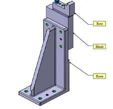
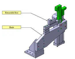
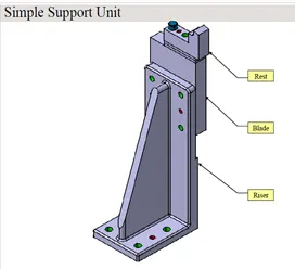
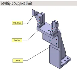
Rest unit consists of few mylars, risers and blades.
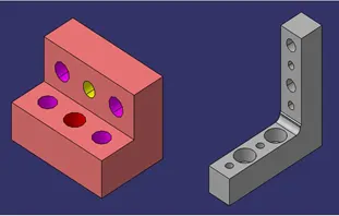
Parts of the rest unit –
NC block/mylars
Risers
Blades
NC block/mylars – it is jaw type, during welding it does not deforms.
It is also known as fingers
Mylars are of two types
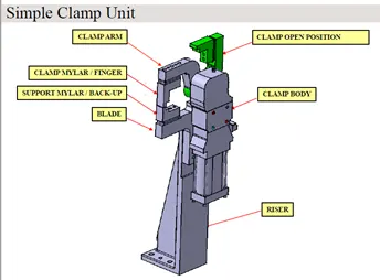
Clamping mylars
Resting mylars
Risers – Risers are manufacturing part used to raise/height the assemblies of fixtures.
One end of riser can be attached to base unit while the other end will be attached to blade
Risers are of two types
L-Type risers
Square tube risers
Q-13) What are the different parts of a fixed unit?
A-13)
Fixed pin units
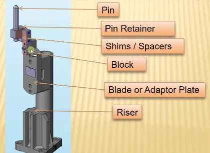
Different parts if fixed units are as follows
Pin
Pin retainer
Shims
Blade
Riser
Pin – the body part is constrained by a set of appropriately locating pin so total constraint by locating pin should be fully constrained at all times to prevent movement
Pin Retainer – It is used to hold workpiece at a constant position
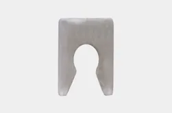
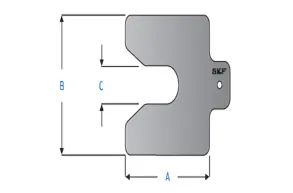
Shims- Shims are typically used in order to support, adjust for better fit, or provide a level surface.
Shims are the small parts which come in the thickness of 0.1mm, 0.2mm, 0.5mm… etc.
They will compensate the stack up tolerance which reflect the mylars
To adjust the mylars for getting the required position shims are used
Shims will be added above the mylars for adjusting according to given tolerance.
L-Type riser – L type risers are of welded type where the stiffener will be added at the centre for support
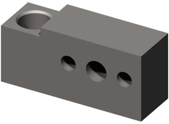
Blade- Blade are the plates which are attached to riser.
Blade is attached or mounted with cyclinders, arms etc.
Q-12) Describe Fixed Pin units & their purpose?
A-12)
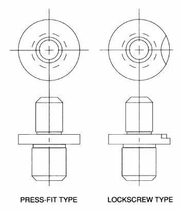
Typically the locating pin are used to locate a body part in a position sufficiently accurate to execute a welding process.
The body part is constrained by a set of appropriately locating pon so total consraint by locating pin should be fully constrained at all times to prevent any movement
Q-11) What are Units? Mention 5 types of units
A-11)
Units can be defined as different components combined together to give a single output. In automobile industry especially in BIW field a single unit plays an important role, for example: - complex robotic mechanism are installed at each assembly station for fixing of door panel and many other parts so that robotic mechanism is also mounted on a station or unit.
A unit can be categorised as -Simple unit
-Complex unit.
Simple unit consists of following-Fixed Pin Unit
- Retraction Pin Unit
- Rough Locator Unit
- Sensor Unit
- Base Unit
- Rest Unit
Complex unit consists of following –
Slide Unit
Dump Unit
Q-10) What do you understand by structuring a design tree? How does it reduce errors during the design process?
A-10)
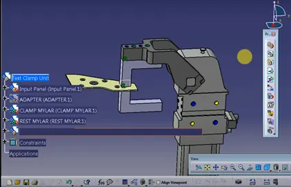
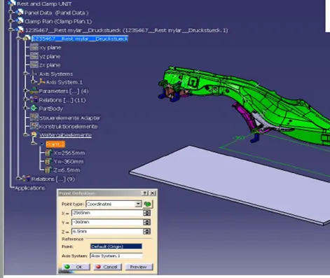
The process where all the assemblies and parts are mentioned according to standard name is known as design tree.
It is an important process which helps to identify a specific part or assembly as to which project, tool it belongs
Q-9) Brief about "Output" in design?
A-9)
Design Output
In a unitized tool it generally requires two types of drawing sheets,
- Key Sheets
- Layout Sheets
- Part detailing
Non Unitized tools.
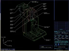
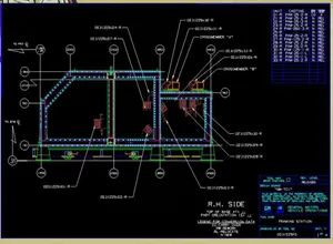
Tool level detailing i.e key sheet layout
Unit level detailing i.e layout and BOM
Part level detailing
Q-8) What are the criteria for percentage completion in the designing stage? Explain it in detail
A-8)
Q-7) What do you understand by Weld study?
A-7)
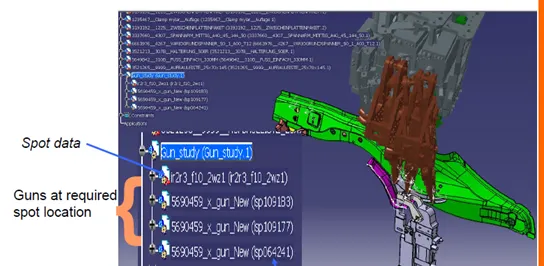
Welding is a fabrication process whereby two or more parts are fused together by means of heat, pressure or both forming a join as the parts cool. Welding is usually used on metals.The completed welded joint may be referred to as a weldment.
Some materials require the use of specific processes and techniques. A number are considered unweldabel a term not usually found in dictionaries but useful and descriptive in engineering.
The parts that are joined are known as a parent material. The material added to help form the join is called filler or consumable. The form of these materials may see them referred to as parent plate or pipe, filler wire, consumable electrode, etc.

Q-6) What is Ergo data?
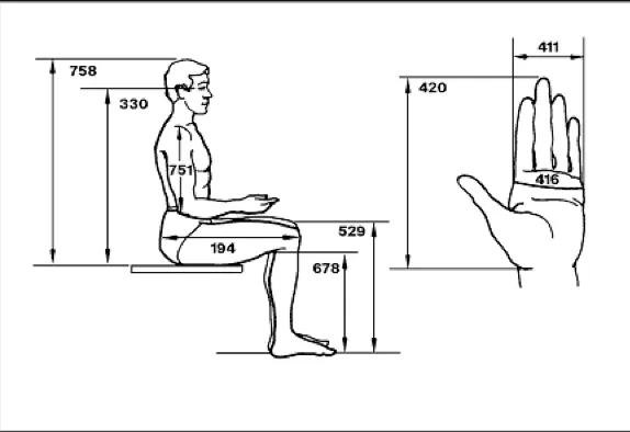
A-6) The application of measurement of products, in order to improve their human use, is called Ergonomics
Ergonomics is the scientific discipline concerned with the understanding of interactions among humans and other elements of a system, and the profession that applies theory, principles, data and methods to design in order to optimise human well-being and overall system performance.”
Ergonomics is the application of a set of average sizes of humans to the design of products. Whatever you design must fit the person who will use it. ... When designing you should consider the shape, weight, height and width of your product. Ergonomics and anthropometrics will provide the data.
Q-5) What is the purpose of a Layout?
A-5) he aim of layout is both to convey the message correctly and to present information in a logical, coherent way making the important elements stand out. Investing into the best logo design can make the content easier to understand.
Good layout is important in every community. This includes: It makes movement easy: When settlement has a good layout, it makes movement very easy, it prevents floods due to the presence of gutters and the spaces in their buildings. It improves sanitation: Settlements with good layouts are well-planned.
Proper layout enhances the look of the particular object and the objects as a whole piece of design in order to create a strong composition. The success of a layout depends on the arrangement of the individual visual elements and relationship — or visual hierarchy — formed between them
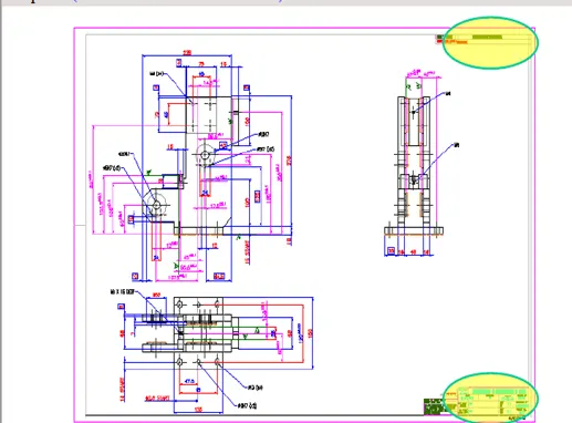
Q-4) What is the Clamp plan?
Q-3)What are the inputs required from the customer to start designing a Fixture
A-3)
Inputs required for car products
GD&T Sheets-
Geometric Dimensioning and Tolerance (GD&T) is a language of symbols and standards designed and used by engineers and manufacturers to describe a product and facilitate communication between entities working together to produce something.
Part list-Parts list , also known as a bill of materials (BOM) is a tabular list of the items used to make an assembly. Parts list is usually combined with the assembly drawing, but it is a separate and individual document and can be and provides a complete list of all parts needed to build the complete project
CAD files of car part-CAD files arevused throughout the engineering process from conceptual design and layout of products, through strength and dynamic analysis of assemblies to definition of manufacturing methods of components.
Clamp Plan
Product assembly process chart
Q-2) What are the inputs required from the customer to start designing a Fixture?
A-2)
Inputs required from customer,
Design Input
- Functional and performance requirement.
- System layout.
- Car product.
- Tool information sheet.
- Weld study information.
- Miscellaneous information.
Functional and performance requirements
- Product process assembly sheet
- Part assembly sequence.
- Sequence of operation.
- Cycle time
- System Layout
- Flow of parts
- Station pitch
- Car Products
- GD&T sheet
- Part list
- CAD files of the car part
Tool Information
- Tool Summary
- Tool Content Sheet
Weld study Information
- Welding Spots
- Welding Guns
Miscellaneous Information
- Customer preferences, standard parts to be used.
- Title sheet informations to be filled.
Informations derived from previous designs and development
Q-1) What is Design Methodology?
A-1)
Design Methodologies are as follows
Design methodologies are in 4 different stages
Stage-1
- Study the system layout thoroughly.
- Study the GD&T sheet
- Reviewing customer input data.
- Determine the number of tools.
- Study the PLP position.
Stage-2
- Retreive the car part.
- Determine the base height from the car part surface.
- Check for the interference with adjacent units or tools.
- Cut final sections and offset metal thickness.
Stage-3
- Retrieve customer approved standard sheets.
- Fill out the title block information.
- Create BOM
- Create layout.
- Create all necessary views.
- Detail the unit according to the customer specification.
Stage-4
- Review information, customer input data and key sheet.
- Plot job for check.
- Compelete check.
- Updating the errors.
- Back Check.