Week 2:- BiW Fixture Basics Challenge
Q-1) What is the process of project execution activity
A-1)
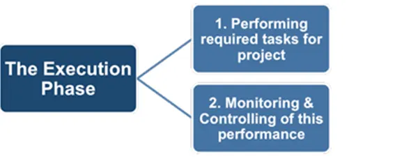
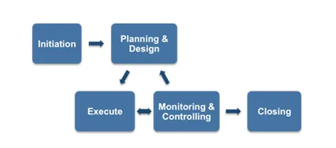
Essentially, work is done according to the project plan and that work is monitored and the results fed back to the people responsible for the plan so that it can be updated to reflect the progress made.
This phase is often called 'Execution and Control' because it does not represent a blind implementation of the initial project plan but rather a cyclical process. As you can see from the diagram above, the planning, executing, and the monitoring and controlling processes are all interdependent.
Executing consists of the processes used to complete the work defined in the project plan to accomplish the project's requirements. Execution process involves coordinating people and resources, as well as integrating and performing the activities of the project in accordance with the project plan. The main output of project execution is the project deliverables and producing these will be the responsibility of the project team who will be working to the project plan.
The actions performed during this process include:
1) Performing the activities needed to meet the project objectives
2) Obtaining and manage quotations, bids and proposals as needed
3) Managing the project team and manage other resources
4) Collecting and analyze performance data
5) Generating project data for status reports and forecasts
6) Managing risks
7) Conducting change control and implementing approved changes
8) Establishing and managing project communication channels
9) Collecting and documenting lessons learned
Q-2) What are the types of joining processes?
A-2)
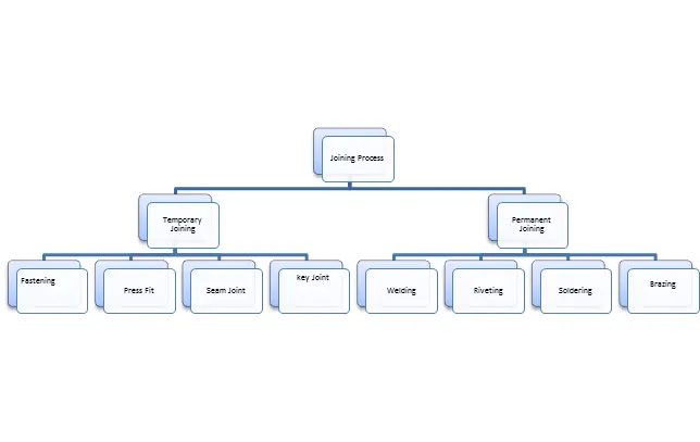
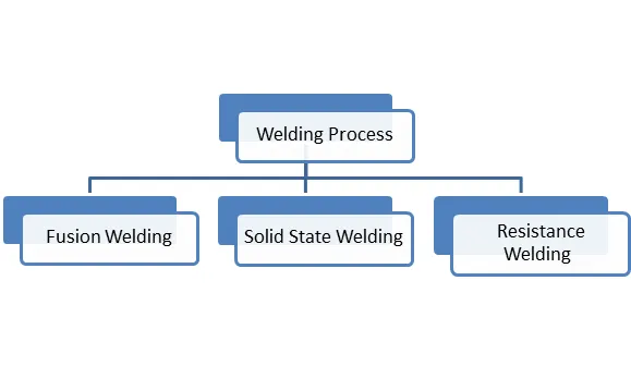
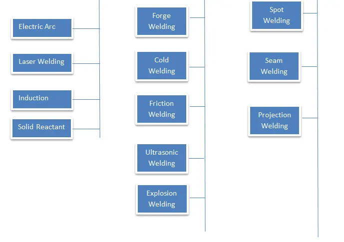
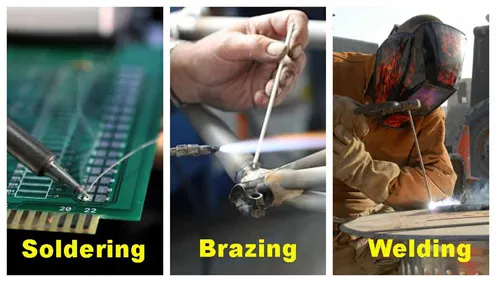
Joining processes includes welding, brazing, soldering, adhesive bonding of materials
They produce permanent joint between the parts to be assembled.
They cannot be separated by external forces.
They are mainly used to assemble parts to make a system.
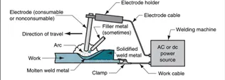
Welding- It is metal joining process in which two or more parts are joined or combined at their contacting surfaces by suitable application of heat and pressure.
Welding is done by applying heat alone, with no pressure applied.
In some, cases both pressure and heat is applied and in some cases only pressure is applied, without any external heat.
In some welding processes a filler material is used to facilitate joining.
Brazing- it is a metal joining process in which two or more metals are joined together by melting and flowing a filler metal into the joint, with the filler material having a lower melting point than the adjoining metal. It differs from the welding as it does not involve melting the work pieces.
During the brazing process the filler metal flows into the gap between the close fitting parts by capillary action. The filler metal is brought slightly above its melting temperature while protected by a suitable atmosphere usually a flux. A major advantage of brazing is the ability to join the same or different metals with considerable strength.
Common Techniques for brazing
- Torch Brazing
- Furnace Brazing
- Silver Brazing
- Vacuum Brazing
- Dip Brazing
Soldering-Soldering is metal joining process in which two or more metals are joined together by melting and putting filler metal into the joint. Unlike welding, soldering does not involve melting of work pieces.
The distinction between soldering and brazing is based on melting temperature of the filler alloy.
Soldering are of two types: - Soft Soldering and Hard Soldering
Hard Soldering- If the solder melts above 800 degree Fahrenheit, it is called hard soldering
Used where a strong joint is needed or where the parts will be used in greater heat than the melting point of soft solder.
The most widely used hard solders are silver alloy the solder that comes from ribbons, sheets, wire or pre-cut pieces of various shapes and sizes.
Soft Soldering: - Soft soldering is a quick method of joining most metal parts such as copper, brass, tinplate and steel.
The process is best confined to light fabrication where the joints are not subjected to heat and vibration and so do not need to be very strong.
Soft solder is an alloy made from varying proportions of tin and lead with antinomy
Q-3) What is Resistance Welding & its application in the automotive sector?
A-3)
Resistance Spot welding is a cost-effective joining technology that continues to be very popular in the automotive industry where high reproducibility and automation are essential criteria.
Resistance Spot Welding is a pressure welding process.
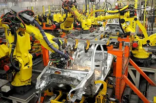
The conventional steel body of a car, on an average, contains 4500 spot weld joints. Resistance spot welding is the principle joining method used in automotive industries and has been for many years.
In this method the joint is produced by the heat generated due to the resistance of work pieces to the flow of current and application of pressure.
The weld is limited to the spots on overlapped work pieces and hence not continuous.
The pointed copper electrodes conduct the welding current to the work spot and also serve to apply pressure to form the strong joint.
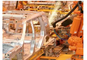
RSW is automated and used in the form of robotic spot welding in automotive industries to weld the sheet metals to form car body.
The advantages of spot welding are many: an economical process, adaptable to a wide variety of materials (including low carbon steel, coated steels, stainless steel, aluminum, nickel, titanium, and copper alloys) and thicknesses, a process with short cycle times, and overall, a relatively robust process with some tolerance to fit-up variations.
Q-4) What is fusion welding & types of fusion welding with its application in the automotive sector?
A-4)
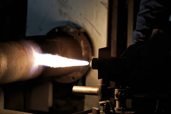
There exist a large number of fusion welding processes and the same can be further grouped on the basis of source of heat. Such processes where heat is applied by means of electric arc are termed as arc welding process. Similarly, all gas welding processes, resistant welding processes, and intense energy welding processes are basically examples of fusion welding.
Advantages of fusion welding processes
- Filler material can be applied easily. So a large lacuna can be filled.
- No need to apply external pressure, so primary shape of the components does not matter (a suitable shape is required to uniformly apply pressure).
- Joint design and edge preparation are not crucial as these parameters affect only achievable penetration.
- More than two components can easily be welded at a step.
Disadvantages of fusion welding processes
- The process is associated with distortion and residual stress generation as it involves melting and solidification.
- Palpable heat affected zone (HAZ) exists in the welded components. HAZ is always considered as the weak portion in welded assembly.
- Mechanical properties of parent materials are also severely affected by intense heating.
- Joining dissimilar metals by fusion welding is challenging task, especially if the metals have substantially different melting point and coefficient of thermal expansion.
- Arc welding processes
- Shielded Metal Arc Welding (SMAW)
- Gas Metal Arc Welding (GMAW)
- Tungsten Inert Gas (TIG) welding
- Submerged Arc Welding (SAW)
- Flux Cored Arc Welding (FCAW)
- Electro-Slag Welding (ESW)
- Electro-Gas Welding (EGW)
- Arc Stud Welding (SW)
- Carbon Arc Welding (CAW)
- Atomic Hydrogen Welding (AHW)
- Gas welding processes
- Air-Acetylene Welding (AAW)
- Oxy-Acetylene Welding (OAW)
- Oxy-Hydrogen Welding (OHW)
- Pressure Gas Welding (PGW)
- Resistance welding processes (many consider this as solid-state welding)
- Resistance Spot Welding (RSW)
- Resistance Seam Welding (RSEW)
- Projection Welding (PW)
- Percussion Welding (PEW)
- Flash Welding (FW)
- Upset Welding (UW)
- Intense energy welding processes
- Plasma Arc Welding (PAW)
- Electron Beam Welding (EBW)
- Laser Beam Welding (LBW)
Q-5) What is the 3-2-1 principle?
A-5)
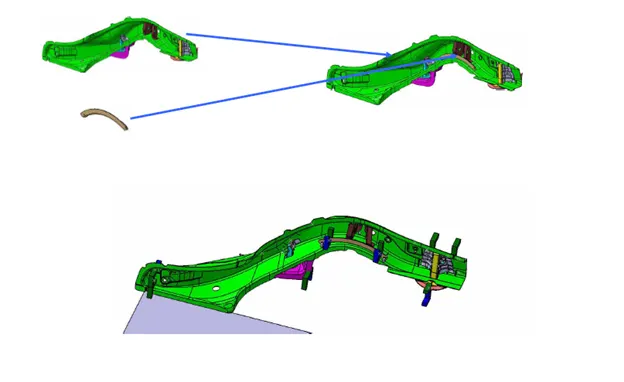
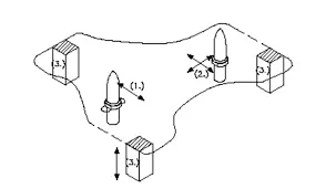
Every part has 6 degrees of Freedom (3 Linear + 3 Rotary) which need to be arrested to ensure proper location of the part in space.
The Location Principle used to achieve this is called the 3-2-1 Principle where:.
3 Stands for-Minimum 3 Rests with clamps to establish a part plane thus restricting 1 Up-Down motion + 2 Rotary motions.
Three locator blocks to establish part plane. Three locators are placed under the part plane. This restricts one axial movement downward and 4 radial movement . Together the three locators restrict five degree of freedom.
2 Stands for– A Round locating pin in a round hole that restricts motion in the 2 directions in the established plane. Round locating pin in a round hole that defines location in four directions perpendicular to the plane established. This restricts four axial directions.
1 Stands for-A Round locating pin in a slot that restricts the rotary motion in the established plane about the round pin. This restricts two axial movements.
Q-6) Define Body coordinate system?
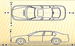
A-6) Body Co-ordinate System
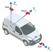
The vehicle coordinate system (XV, YV, ZV) used by Automated Driving Toolbox is anchored to the ego vehicle.
- The XVaxis points forward from the vehicle.
- The YVaxis points to the left, as viewed when facing forward.
- The ZVaxis points up from the ground to maintain the right-handed coordinate system.
The vehicle coordinate system follows the ISO 8855 convention for rotation. Each axis is positive in the clockwise direction, when looking in the positive direction of that axis.
Q-7) Elaborate Body plane system & its essentials.
A-7)
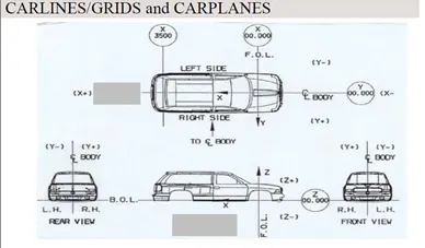
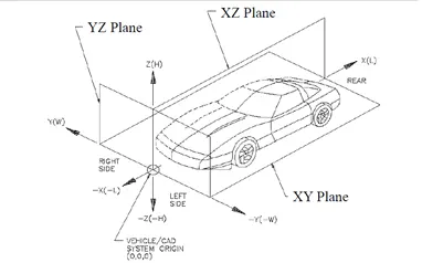
Every Product Design is done with respect to the Origin of a Universal co-ordinate system wherein the co-ordinates of the Origin are X=0, Y=0, Z=0
Every point of the vehicle gets identified with a unique co-ordinate.
This co-ordinate system becomes the common reference for the various agencies working simultaneously to produce a vehicle.
It is used to certify tooling and becomes a buy-off criteria between the various agencies
The directions are as follows
X is along the Length of the vehicle
X increases in positive direction from Origin to vehicle Rear and increases in negative direction from Origin to vehicle front. It is also called the “Front O Line” (F.O.L.) or the Fore-Aft direction (F/A).
Y is along the Width of the vehicle
Y increases in positive direction from Origin to vehicle RH and increases in negative direction from origin to vehicle LH. It is also called the “Center O Line” (C.O.L.) or the Cross-Car direction (C/C).
Z is along the Height of the vehicle.
Z increases in positive direction from origin to vehicle Top and increases in negative direction from origin to vehicle bottom. It is also called the “Body O Line” (B.O.L.) or the Up-Down direction (U/D).