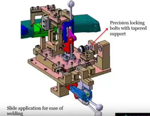
Week 3:- BiW Fixture Design Methodologies Challenges
1)
Design Methodology :
The design methodolgy is the process where the details about the steps involved in the design are inferred.
There are several methods involved in designing the Fixture design.
They are
- Purchase Order
- Customer Input
- Percentage Completion Criteria
- Design Output
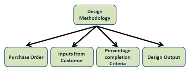
While designing the fixtures, The fixture data shouldnt be submitted alone. The data has to be submitted with the 2D drawing and the documentations.
2)
Input from Customer :
The process is taking the order from the customer at the start of work .In this process, we ask from the customer what function this model serves and try to get most of the standard components. Then the products information, layouts, ergo details, weld spots and study of the welds in the fixtures.
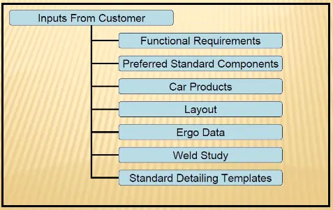
We will get the input from all the design aspects and the styling surface and the work will be started with the reference of the input surface. Then the assembly line constraints such as flow of part, station pitch, robot stations, platform heights, loading and unloading of the parts details are gathered from the layout.
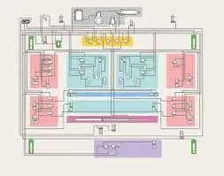
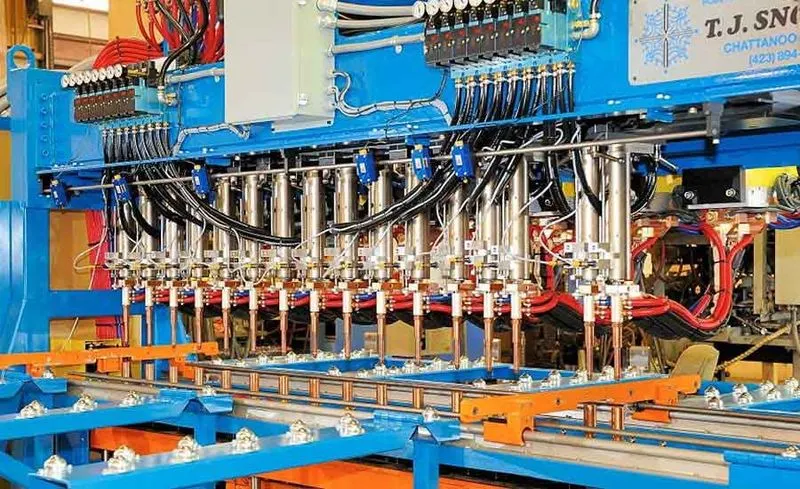
We also get the ergo data, Weld study and other inputs as well from the customer to satisfy the manufacturing layout and the effieciency of the products that is up to be manufactured.
3)
Car products :
The car products are the panels like Hood panels, fender panels, door panels etc.
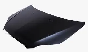
In this process we get the process involved or the process carried out in the manufacturing of the fixture. Process like hemming, welding, checking storage etc. are carried out here.
Preffered standards :
the process explains what standards are available and what processes are used in the manufacturing process of the fixtures. There are standards like ABB, NAAMS, DESTACO, ZYTRAN, TUNKERS are used in the manufacturing index. While manufacturing, we use standard parts for saving most time and money.
It also discusses about the components that are being used in the process. It also discusses about Tip Dressers (Tool sharpening method).
From car products we will infer all the design for construction of the parts from thereon. We will build the design on the part panel with taking them as reference and we will be working on them to entirely develop the component.
4)
Clamp plan :
The clamps or fixture clamps are used for machining of dimensionally stable workpieces in single or multiple clamping fixtures. Due to their compact design they can be arranged in a very limited space. The fixture clamp is only suitable for exterior clamping.
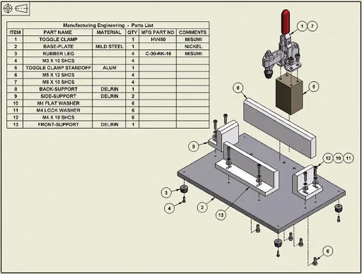
The clamp plan is the plan data that provides the exact location where the calmps are gtting placed in the fixtures to provide the appropriate support and arresting the degrees of freedom of the workpeice in all possible direction. The MCS Master control surface will provide the designer with the data of the clamping sequence from the GD&T data sheet.
The clamp plan also provides the info about the workpeice's clamping points where the fixture is prepared in accordance to it.
5)
Layout :
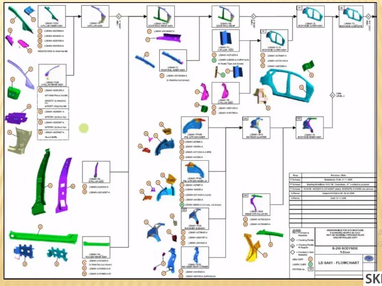
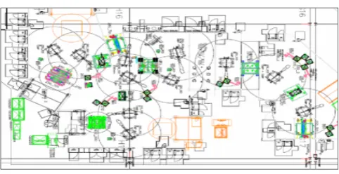
The purpose of the layout is that, it shows how the componens travels in the assembly line and how the robots and other stations are placed to get the maximum coverage of operations in the path it covers.
It shows basic features like
- Robot coverage area - Basically it shows the working area covered by each robot working on the area.
- Flow of parts - This shows how the flow of the workpeice is going to happen on the assembly line and how the part is approaching the station .
- Station Pitch - It shows how much gap is there between the stations which gives us a idea of how the workpeice should travel to get the most beneficial output out of it.
- Sub Assembly Links - It shows how the sub assemblies are assembled togather and how they will be joined to other sub assemblies and finally form a main assembly.
- Platform Heights - It shows the height of each platforms and how high the workpeice has to be lifted.
- Loading and unloading - As the name suggests, it shows how the loading and unloading of the parts are done.
6)
Ergo data :
The ergo data denotes the ergonomical data. It basically comes into picture when there is manual labour is required.
This study generally deals with the human behaviour of the labour who is going to work around the workpeice and then the fixture for the part will be designed.
The fixture generally takes the data of the worker with the basic measurement standards such as 95th percentile and then designs the fixtures accordingly.
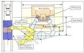
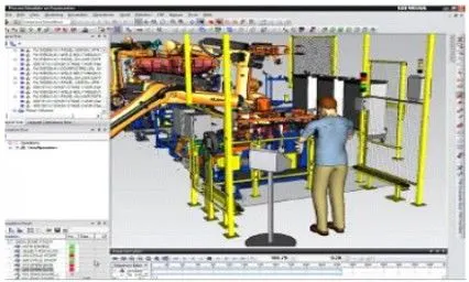
The ergo data is also produced with respect to the workpeice informations such as loading height of the workpeice so that the workpeice is not lifted so high while inturn results in the shoulder tiring workout for the labour.
It also takes the consideration of the safety parameters to ensure the safe work operating zone for the worker who works around the workpeice.
7)
Weld Study :
The weld study is the study of the welding spots that are going to welded on the workpeice. It also shares information about the weld gun that is used for the induction process of welding. It also shows how to use and where to use the specific seleced gun.
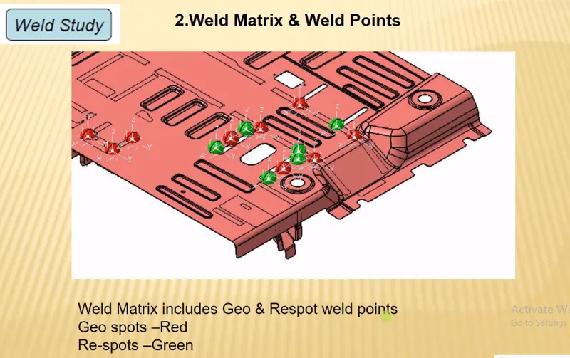
In general terms, all the weldments in a workpeice are not done in a single shot.
The welding are done in a sequencil order for compensating the parts that are going to sit on.
For instance, the welding spots are done for the workpeice first and then the reinforcements are coming in the picture and other welds for the weldments and the workpeice are done.
The red spots are indicating the spots done by the Geo spots.
The green spots are indicating the spots done by the re-spots.
8)
Percentage Study :
The percentage study denotes the percentage of the work that has been completely in the given time period.
When the car product data are given to the designer, it marks the day 1.
Untill the designer completes the Input and the concept design, it is graded as less than 25% of the work completion. In the conceptual design, the designer completes the design with the conceptual design where he makes the design as it can fulfil its created purpose. This point marks the 25% completion of the workpeice.
If the design is completed the design is send to the simulation team, where they check with the simulation and revert back to the designer again with the errors or satisfied results. This step marks the 40% completion of the process.
The simulation teams checks for the all aspects where in the design could end up in failure and give the report to the designer. The designer again updates or revises the model and then gives the revised model to the simulation team where they again do the checks to check if the new update gives any error with respect to the model.
Detailing and the design freeze in the project marks the 40 to 85% completion of the model in the process.
9)
Output :
The output process in design consists of lots of designs in 3D designs and 2D drafts in the documentation process alonfg with the report of the workpeice. This data is then given to the next team for manufacturing the workpeice. Therefore the output process is divided into two digitised process. They are
Unitised tools and Non Unitised tools
Unitised tools :
The unitised unit is the unit that gives you detailed drawing information and it also gievs you the information about how the components are designed. They are further more classified into two steps. They are
- Keysheet - It also shows the design in orthagonal or isometric view. It shows the information about the location of every units in the particular fixture.
- Layout sheet - It shows information about the assembly line and how the parts are going in out of the path in the assembly.
Non unitised tools :
This type of tool doesnt require a keysheet. Example - buffer storage and tool changer. Tools that require no input from the fixtures and the information about them is given in the layout sheet.
10)
Structure Design Tree :
It is an important process which helps us to identify a specific part or assembly, as to which project, tool or unit, it belongs to.
The structure design tree will be the index of all the components in the fixtures and also it is very important feature in the fixtures because it helps to identify all the manufactured part in whole fixture. Every manufactures will ask for any standards to which he can simply take as input and work on the system as every customer company has their own standard parts. This will reduce the effort that has to be put in by the manufacturer and also reduces the expenditure of time and money.
This helps us to avoid the errors during design study, manufacturing, assembly, inspection etc. If the parts or assemblies are not named properly or the design tree is not structured properly, it will create confusion to understand the design & may create major possibilities of making an error. Naming of the Fixture or a unit or a part, gives the information as to which the project or zone or assembly do they belong. It can help us to identify the quantity of items of same type or different types that are being used in an assembly.
The structure tree promotes easy understanding and also it helps in creating a workpeice's fixture without any doubts.
11)
Units and its types :
An unit is an assembly that consists of several sub units like Clamping unit, Loacator units, Resting units/ Docking stand and other sub assemblies. In fixtures, there are many types of units present to carry out the specific operation.
According to the process that are carried out in the fixtures, 3-2-1 process pins and clamps are created.
there are many types of units that serves differenrt purpose and ultimately helps in making the workpeice from the from scratch with the help of Fixtures.
The types are
- Fixed Pin Unit
- Retract Pin Unit
- Rough Locator Unit
- Rest Unit
- Base Unit
Rest Unit - It is used to rest the components
Fixed Pin Unit - It is used to arrest the motion of the component
Base Unit - All the units or sub assemblies are placed over the base unit.
Retract Pin Unit -It has pin retracting unit that is used to move pins to ensure proper loading and unloading of the component.
Rough Locator pins - It helps in correct loading of the components.
12)
Fixed Pin Unit :
It is the non movable pin that usually arrests the movement of the component in fixture.
Every fixture has a Fixed pin unit that usually helps in arresting some of motion that the part has, when it is freely suspended.
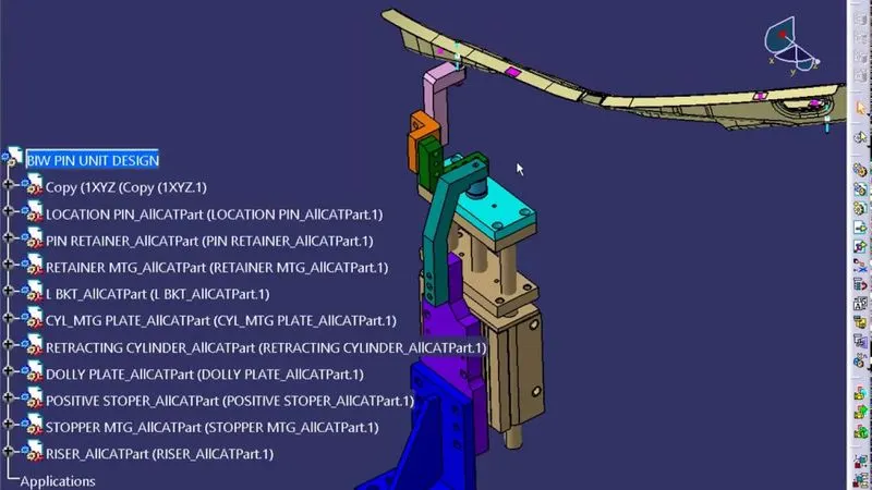
The salient features of a pin units are
- It is used to locate the component
- Two pins are used to locate the component
- First pin restricts four translational motion
- Second pin restricts two translational motion
- totally they arrest six degrees of freedom
13)
Parts of a Fixed unit
Fixed Pin Unit is a non movable locating unit that is used to arrest six degrees of motion. They are four translational motion and two rotational motion.
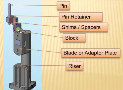
The parts in the Fixed uints are
- Pin
- Pin Retainer
- Shims
- Block
- Blade
- Riser
PIN :
They are used to locate the component and totally two pins are used. They in total constrain 8 degrees of freedom.
PIN RETAINER :
They are used to hold the pins
SHIMS :
They are basically used as spacers in the unit.
BLOCK :
Blocks are the components that comes in different shape according to the fixtures in which they are used.
BLADE :
These are the components that are used in risers to adjust the riser to the blocks.
RISER :
They are used to increase the height of the Unit.
14)
Need for Rest unit :
The rest surface are the surface that are used with the Mylars within the fixture. As rest unit is simple to manufacture and require less cost to produce. The rest unit is used for comning the clamp unit and locator unit. The rest unit is like a dock surface.
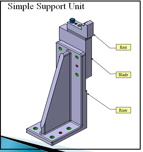
The parts of a Rest Unit are
- REST - The rest is the part where the component is placed on the rest unit.
- BLADE - Blades are bolted on the riser.
- SHIMS - They are used to compensate tolerance stack up. In pin unit we need to control two direction that are X and Y using shims or space. They generally are used to increase the heighth to match the components or workpeice's hole or other parts positioning so that they are matching perfectly.
- RISER - The riser is used to increase the height of the Unit.
15)
DESIGN OF THE SENSOR UNIT :
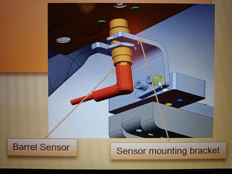
The sensors are used for measuring the physical property.
The unit whichbis built to sense the components ior car panelusing the electrical sensors are called unit sensors.
The output signal of sensor is then send to PLC ( Programmable Logic Control ) for further purposes.
There are different types of sensors such as ultrasonic sensors, Light sensor, Proximity sensors, water flow sensors etc.
The reason for the fixture to use sensor is that each component that are used in the fixture should be sensed. The car panels that are placed in the fixtures are being sensed by the sensors for their presnce and after that the process is carried out. This also ensures that the assembly that are used are manufactured with less errors. If there are multiple sensors used in the fixtures in different places to minimise the error in the workpeice.
16)
Rough Locator Unit :
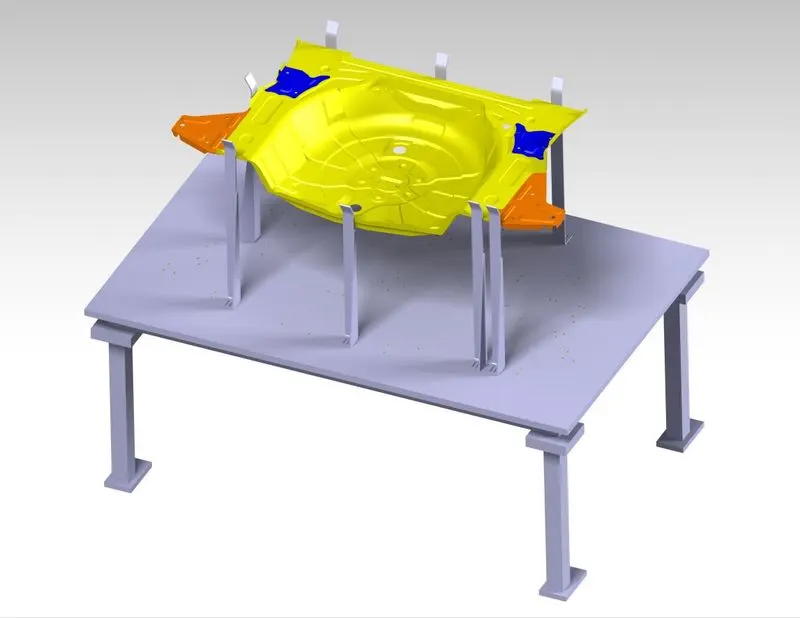
The rough locator unit is the unit that is used to locate components correctly in the fixture. It guides the operator while loading components in the fxture. Basically it is designed accordingly to fit our components. They basically perform the following steps in the unit. They are
- They are usually used to guide the component while loading and unloading the components with ease
- They have extra legs that are placed in such fashion that the boundary of the workpeice are touching so the part sits in perfectly.
- They help the pins to sit in the workpeice to arrest motion.
- Entry angle should be 30 to 45 degree and rough locator should start guiding the component before 10 to 15 mm to start the pin engagement.
- The easy adjustments, the rough locators are placed on the base with slots in it.
17)
Base Unit :
It is the unit that acts as a base to the unit that is going to be placed on top of it. The units that lie on top of the base unit are rest unit, sliding unit, clamping unit etc.
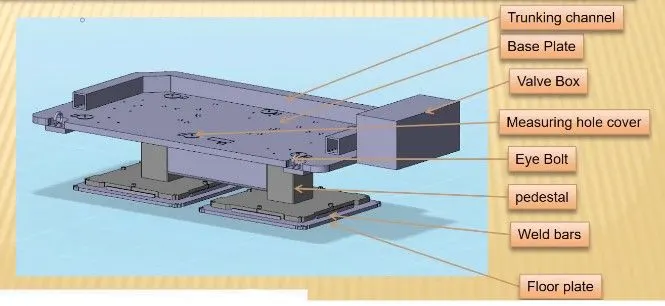
The parts that are involved in base unit are
- Floor plate - Plate that is used to join fixture and floor called floor plate
- Weld bars and pedastals - Pedastal is support or base on which fixture is mounted
- Eyebolt - They are used to give angular constraints as it can sustain 45 degrees of angle.
- Measuring hole cover - They are commonly known as the tooling hole from which the oter holes to the base are being drilled. These holes that are created are the reference holes. They also can be covered using measuring holes cover.
- Base plate - This plate is the plate on which all the other units are connected. These are very strong unit which is generally created this way to sustain the load of the workpeice.
- Trunking channel - Pneumatic fixture consists of solenoid valve and these valves are placed inside valve box. The trunking channel protects all the inlet valves which are attached to the Pneumatic systems such as cylinders, press, claamps etc.
18)
Dump Unit :
Dump unit is the unit that is used in a fixture as there is a external componrnt that has to be added in the workpeice. Basically, it is a space that is being created for the lack of space in the fixture. This is a complex cylinder consists of dump cyliner which is being used for clamping or unclamping of the component.
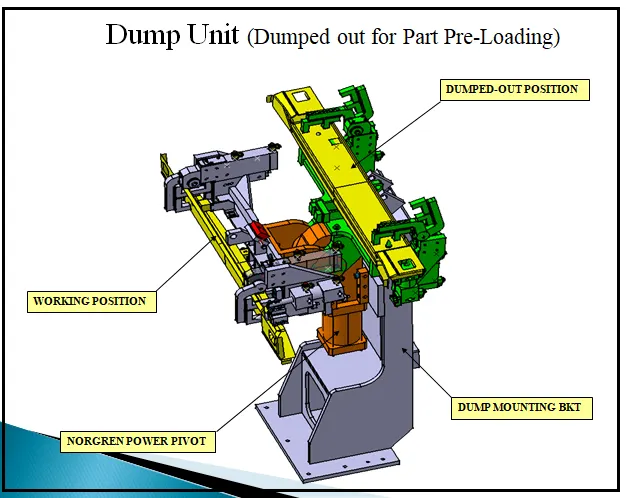
These are generally used in the system or in a unit where there is space constraint for holding the workpeice. The working position holds the position where the extra part from the base unit workpeice is going to sit on and get worked on. The dump mouting bucket is the place where the extra parts are collected in there. The out position is the one where the top of the workpeice is holded, or they work like the clamping unit.
19)
Slide Unit :
The slide unit is the unit that are otherwise known as posotioning units used to position fixtures, weldguns, units and robots. This unit consists of a rail that slides along with the entire units. The entire unit slides along with the sliding unit. It usually consists of open and close positions. These sliding unit is commonly used in automotive industry for different similar components.
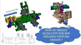
The sliding unit is the unit that has a rail that workpeice will sit upon it. When there are any operation going on or if the rail is sliding over the base unit, then the workpeice that is being connected to the rail will also move. For instance, if the workpeice has to move to a certain location to get another operation, as the robot has its arms constraints in distance and it cannot access the workpeice where the operation has to be carried out. In this case, the sliding unit that is placed on the top of the base unit can move the rail and this moves the unit towards the direction of the robot, so the robot can reach the part where the operation can be carried out. therefore the sliding unit does a major work in reducing the cost of the fixture or else the fixture's length is higher and more robots has to be placed to compensate the work or the workpeice has to be operated in two different station which is again a tedious task for the manufacturer to carry out.
The commonly use of sliding unit is found in the welding unit.