Week 3:- BiW Fixture Design Methodologies Challenges
1. What is Design Methodology?
Design methodology is the broader study of method in design, the principles, practices and procedures of designing. Steps followed during the concept designing stages of Fixtures design.
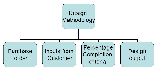
Purchase Order :
Conformation order from the customer to start the project work in form of the written document or mail. It gives clarification about the project need and start planning and purchase the parts or asseblies within the specified due date.
Inputs from Customer:
We need to get detailed specifications from the customer related to the concepts,standards for parts and assembly, manufacturing techniques,tolerance levels,drafting sheet for designed parts etc.
Percentage Completion Criteria :
Percentage completion criteria is project levels of completion
0-25 % - Input and Concept Design
25-40 % - Concept approval and Simulation Check
40-85 % - Design Freezing and Detailing
85-100 % - Check and Final Dispatch
Design output:
Its related to 2D detailed drawings and 3D models.
Detailed description about the tools going to be used.
Unitized tool : common base multiple opearations in sequence.
have key sheet and Layout sheet. Key sheet describes units and their placement (position and orientation) , Layout sheet is about detail drawings of individual parts and also for assemblis.
Non-Unitized tools: Stand alone tool can perform only one operation having only layout sheet.
2. What are the inputs required from the customer to start designing a Fixture?
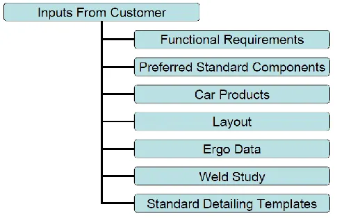
Functional Requirements :
Funtion that fixture is going to perform like welding, gluing, fastening, rivets,hemming etc.
Preffered Standards:
Use as many Standards components as possible in the assembly. It saves the production time and cost of the final product will be come down. Design phase will be simplified and customer provide requirement regarding the standards they need. OEM Standards include NAAms,FAUNC,Tunkers,Siemens,ABBetc.
Components include riser, L blocks,pins, clamps,switches,sensors,gearbox etc.
Car Product:
Include GD&Tstandards, parts list, cad files in 2D detailed drafting and 3D models, clamp plan.
Layout:
Flow chart , station accesories ,platform height.
weld study:
Types of weld, weld gun,hot spots
Ergonomics :
Deals with the comfortability of the operator
3. What is the input we get from "Car Products"?
Car Product:
Include GD&Tstandards, parts list, cad files in 2D detailed drafting and 3D models, clamp plan.
GD&T:
GD&T provides information about locating the pins, rest,clamp,dumps &slide information. while mounting they can use that data and mount the parts with pins or clamps.
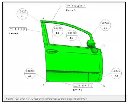
Part List :
Detailed description about the list of parts and assembly used in the project. project details, assemblies reference, part reference,part number, tools list, thickness information of each.
Cad Files :
Include the 2D detailed drafting of parts and assemblies used in the deign and alos with 3D models will be provided for manufacturing the part.
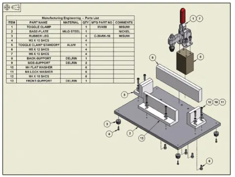
Clamp Plan:
Clamp plan gives you an idea where you need to hold the part in assembly line.
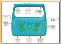
4. What is the Clamp plan?
Clamp plan gives an idea exactly where to hold the parts during inspection or resting or during the assembly or joining process.
Detailed description for the placement of pins or clamps will be provided with reference to the coordinates value both in local coordinates or as well in body coordinate system.
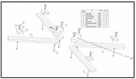
Clamp have some basic requirements as follows
- It need to hold the workpiece rigidly during operations.
- It should not damage or deform the part.
- Less time for loading and unloading the part.
- All degrees of freedom of the workpeice should be arrested.
5. What is the purpose of a Layout?
Layout gives an idea about how the components are placed in the assembly line and operations limits of each assemblies or subassemblies and also the conveyor lines or robotic operation limits.
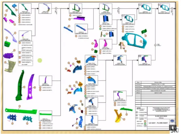
- It gives details or flow chart about the flow of components in subassemblies and between main assemblies.
- Lead time between stations and substations.
- Accessories like tool changers or grippers.
- Robotics operations and area coverage of the arms and how many operations that particular tool or robot is going to perform.
- Detailed Bill of Materials with the project requirements and level of completion can be checked over each stage with the tracking id.
- Load and unload the components
- Platform height required for different operations.
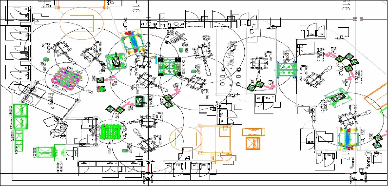
In above example , first robot will perform only one operation and one product at a time where as the later ones can able to work with multiple parts or with multiple machine access.
6. What is Ergo data?
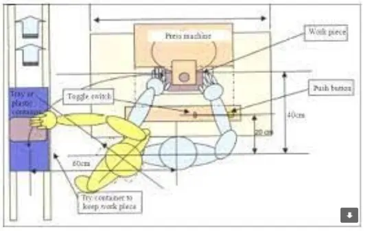
- Human comfortability while performing the operation.
- Manual labour is employed for performing the operations or robotic.
- Ergo data gives information of platform height , Loading height based on that fixture for the part will be designed.
- workpiece specifications and tool movements relative to the operations.
- Worker safety zone
- Human behaviour who is going to work around the workpeice and tool
- Consideration of the safety parameters to ensure the safe work operating zone for the worker who works around the workpeice.
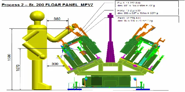
7.What do you understand by Weld study?
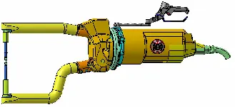
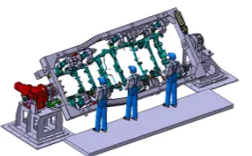
- Study of the welding spots where to perform welding on the workpeice. Weld gun details that is used for the induction process of welding. It also shows how to use and where to use the specific seleced gun.
- All welds in a workpeice or asseblies cannot be done in a single shot.
- The welding are done in a sequencil order for compensating the parts that are going to sit on or clamping requirements. .
- For instance, the welding spots are done for the workpeice first and then the reinforcements are coming in the picture and other welds for the weldments and the workpeice are done.
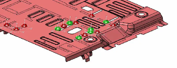
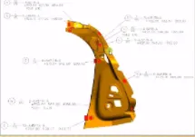
- The red spots are indicating the spots done by the Geo spots.
- The green spots are indicating the spots done by the re-spots.
8. What are the criteria for percentage completion in the designing stage? Explain it in detail?
Percentage completion gives an idea how much work is completed or progress state of the project.
0-25 % - Input and Concept Design
25-40 % - Concept approval and Simulation Check
40-85 % - Design Freezing and Detailing
85-100 % - Check and Final Dispatch
- Input from the customer related to the specifications and made conceptual design, the designer completes the design, which serves its functional requirements and standards based. This point marks the 25% completion of the workpeice.
- Completed design are send to the simulation team, check with the simulation and errors are noted and modications happens. The simulation teams checks for the all aspects where in the design could end up in failure and give the report to the designer. The designer again updates or revises the model and then gives the revised model to the simulation team where they again do the checks to check if the new update gives any error with respect to the model.
- Detailing and the design freeze in the project marks the 40 to 85% completion of the model in the process.
- once everything is finialsed they will do quality checks and dispatch the product to the customer.
9. Brief about "Output" in design?
Design output:
- Its related to 2D detailed drawings and 3D models.
- Detailed description about the tools going to be used.
- The output process in design consists of lots of designs in 3D designs and 2D drafts in the documentation process alonfg with the report of the workpeice. This data is then given to the next team for manufacturing the workpeice. Therefore the output process is divided into two digitised process.
Unitized tool : common base multiple opearations in sequence have key sheet and Layout sheet.
Key sheet describes units and their placement (position and orientation) ,it shows the information about the location of every units in the particular fixture.
Layout sheet is about detail drawings of individual parts and also for assemblies,It shows information about the assembly line and how the parts are going in out of the path in the assembly.
Non-Unitized tools: Stand alone tool can perform only one operation having only layout sheet.
Example - stands , buffer storage and tool changer. Tools that require no input from the fixtures and the information about them is given in the layout sheet.
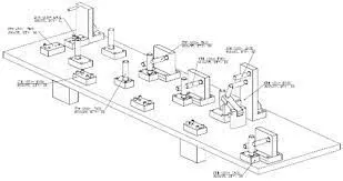
10. What do you understand by structuring a design tree? How does it reduce errors during the design process?
To identify a specific part or assembly, as to which project,assemb tool or unit, it belongs to.
base unit at first followed by standard parts next will be bought out parts.
Different customers have different set of standards for the structuring a design tree.
Helps us to avoid the errors during design study, manufacturing, assembly, inspection etc.
If the parts or assemblies are not named properly it will create confusion to understand the design & may create major possibilities of making an error of parts attached to wrong assembly.
Naming of a Fixture or a unit or a part, gives the information as to which project or zone or assembly do they belong.
To identify the quantity of items of same type or different types that are being used in an assembly.(Bolts, nuts, repeated parts )
Example:
POO1_AS_SAS_ST_A00_P00_F
P00 is project
AS is assembly line
SAS is subassembly line
ST is station
A00 is assembly number
P00 is Part number
F is front part
11. What are Units? Mention 5 types of units.
- Unit is an assebmly having a list of parts which will perform specific functions like welding, gluing, resting , inspecting etc. Locating the part is acheived by 3-2-1 prinicple.
- A fundamental issue with the metalworking process is locating the part to be machined, punched, bent, or stamped relative to the work platform.Hence, the accuracy with which a part is machined is quite dependent on the accuracy with which it is positioned in the fixture.
- Any variation in part location on the fixture adds to the dimensional tolerance that must be assigned to the finished parts and affect the surface finish of the components.
- Improper support or clamping can temporarily or permanently deform the part. Hence, techniques for supporting and clamping must be considered together with the method of locating in order to assure repeatability from part-to-part.
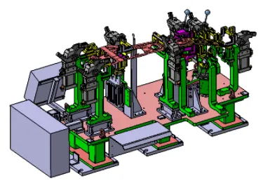
Types:
- Fixed pin unit
- Retractable pin unit
- Rough Locators
- Rest unit
- Base unit
- sensors unit
12. Describe Fixed Pin units & their purpose?
- Fixed Pin unit is a unit designed to locate the car panel using pins.
- Locate the object in a position to perform the operations.
- Fixed pin unit is arrest the movement of component in fixture in all directions(translationas and rotations) considering the DOF of object.
- Two directional shims are used to prevent the rotational movement of the object.
- Shims are used to compensate the tolerance offset values.
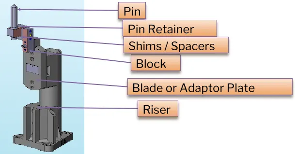
13. What are the different parts of a fixed unit?
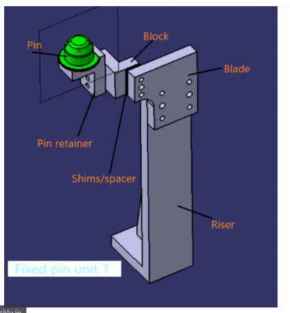
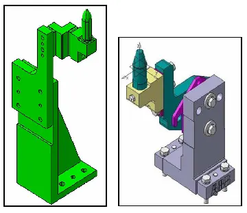
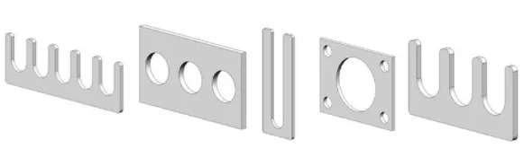
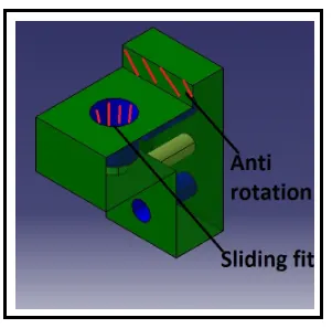
Shims:
Shim is a thin and tapered piece of material used to fill small gaps between the components. Sims are used to adjust for better fit of close tolerance. (0.1,0.2 upto 5mm)
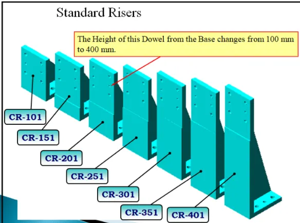
Risers:
Riser is a structure used to mount the clamps and rest. can L shaped, square or frame type.
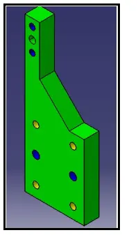
Blades:
The plate which connects Riser to the Clamp cylinder is named Blade. This plate plays an important role in building the unit. The plate can be of any shape. But we need to keep in mind that the plate should be as compact as possible.
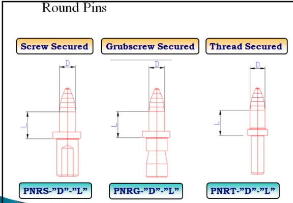
Pins:
Pin diameter should be cylindrical grinded to maintain the dimensionsal accuracy used to locate the panels. standard pins should be used as far as possible.
Round pin
Diamond Pin
Pin Retainer:
Designed to hold the pin in a place and also to rest the pin in a position.
14. What is the purpose of making a Rest unit & describe its parts?
A rest unit is a unit designed to rest / support the car panel using NC blocks / Mylar / Rest. And below are the different parts of a rest unit in general.
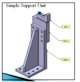
Rest unit is combined with other unit to reduce the cost of overall project cost.
It has a raiser and a normal blade , a spacer and shims to adjust the tolerances offset.
Shims:
Shim is a thin and tapered piece of material used to fill small gaps between the components. Sims are used to adjust for better fit of close tolerance. (0.1,0.2 upto 5mm)
Risers:
Riser is a structure used to mount the clamps and rest. can L shaped, square or frame type.
Blades:
The plate which connects Riser to the Clamp cylinder is named Blade. This plate plays an important role in building the unit. The plate can be of any shape. But we need to keep in mind that the plate should be as compact as possible.
Pins:
Pin diameter should be cylindrical grinded to maintain the dimensionsal accuracy used to locate the panels. standard pins should be used as far as possible.
15.What are the basic fundamentals to design a Sensor unit?
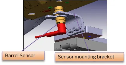
- A sensor unit is to sense the car panel by using Electrical sensors. This signals from the sensors will be feed to the PLC and so the next process will be executed by this signal to identify the components.
- Sensors should be adjusted in all three directions.
- Every single loose panel which are being welded in a tool should be sensed.
- Each panel should be sensed by 1 to 2 sensors depend on the size of panel
- Preferred to be in diagonal opposite ends of panel.
- Every sensor should be mounted in a 3 direction adjustable way in general.
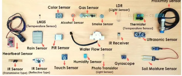
Types of sensors used in general :
- Proximity sensors
- LASER sensors
- Photoelectric sensors
16. What is a Rough locator unit & what are the basic fundamentals to consider while designing it?
- Guide the operator to locate the pin accordingly
- Panel edge should be same as the location of rough locators
- Its will be provided with two slots to move inwards or outwards. The slots should be in the direction of car part guiding.
- A rough locator can be of standard part or make part.
- Rough locators has to be placed in the same angle of the car part edge with a minimum distance of 2-5mm from the edge of the car part.
- Rough locators should start guiding the panel before 10 to 15 mm to the start of the pin engagement.
- Rough locators should be designed with entry angle for car part entry.
- Rough locators should be designed with two slots to mount for easy adjustments.
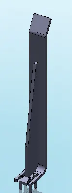

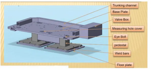
17. What is a Base unit and describe it's parts?
A base unit is the unit designed to mount all the other units like Clamp unit, Pin unit, rest unit,tool.
Its already holds the tool like pneumatic valve box, trunking cable path will also be mounted on to a base unit.
Floor Plate:
Used to join the fixture and floor
Weld bars :
used to mount the welding components like weld gun
Base plate:
plate where all units are mounted. Thickness of the plate should be sufficient to hold all the parts together.
Valve box:
Valve box stores the gas which requires for pneumatic components. Consists of solenoids valves and trunking channel protects all pressure inlets which is attached to all pneumatic devices
Eye bolt :
Move the fixture with the help of electric relay signals or manually with the ropes. Also to lift the base unit.
18. What is a Dump Unit and what are its functions?
Dump unit is hold all the assembly components in a particular constrians to perform the welding process or applying glue or hemming process.
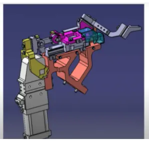
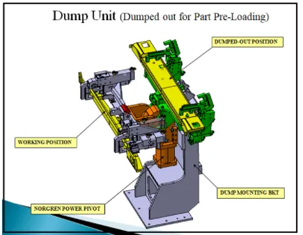
- Dump cylinder have open and close position to hold the parts.
- Dump cylinder to perform the operation of clamping and unclamp the car panels.
- It have more than one cylinder to perform more operations at the same time.
- Open to remove close to hold the component.
19. What is a Slide unit? Mention where Slide units are commonly used.
Slide units have adjustable strokes, managed by rolling ball screw, and are suitable for the assembly of series spindles.
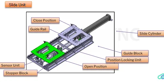
Used where lot of space constrians are there where we have sliding cylinder which expands.
Sensor unit:
used to sense the position guide rail.
Stopper Block:
prevents the movement of the slider with certain distance limits.
Position Locking unit:
unit to stop the movement of the slide when its operating.
Slide Cylinder :
used to open and close the piston rod to adjust the rail