Week 3:- BiW Fixture Design Methodologies Challenges
- What is Design Methodology?
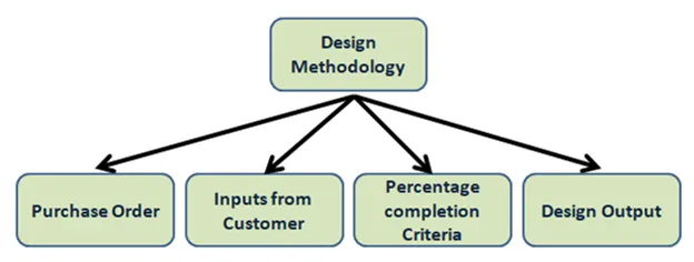
- Design methodology is the steps that is needed to be followed during the concept stage of design.
- Purchase order: - It is the first official document that we will receive from customer side, this document will basically give confirmation to us that the customer has agreed to our deal and we can start the project.
- Inputs from customer: - Inputs from the customer is the demands of the customer that we need to fulfill. Inputs like functional requirements, preferred standard components, car products, layout, ergo data, weld study, standard detailing templates. This all details are given by the customer to us.
- Percentage completion criteria: - Every project is divided into various stages. These stages will be assigned specific percentage value for the time it is needed to be completed, and by analyzing these percentage we will come to know how much our project is completed.
- Design output: - The design output will be a 3rd part, documents, 2D drawings, bill of materials, key sheet, layout sheet etc. will be included in this output.
- What are the inputs required from the customer to start designing a Fixture?
- Input from the customer is the certain demands that customer has from the project and we need to fulfill it. Input from the customer is given below-
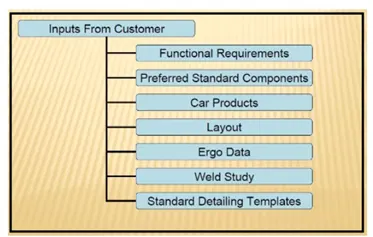
- Functional requirements: - It is the first input which will define for what purpose the fixture is being made, whether the fixture is made for welding, hemming, riveting, inspection etc. will be mentioned. This is an important factor as based on this input the entire design and development of the fixture is dependent.
- Preferred standard components: - During the development of any project the team always decides to involve as much as standard parts as possible. This will save the time involved in designing the part, which in turn will reduce the cost of the project. ABB, NAAMS, TUNKERS, ZYTRAN, DESTACO etc. produce some standard parts which are used in fixture design.
- Car products: - It is the input we receive from the customer. This include the 3D CAD model data, GD&T of parts, clamp plan, product assembly process sheets etc. these inputs are necessary to begin the project.
- Layout: - Layout gives the information about the flow of parts, robot station, tip dressers, tool changers, platform height, loading and unloading sequence etc. layout gives us the understanding of the complete assembly line.
- Ergo data: - Ergo data gives the interaction of the human behavior during the assembly line. It will include data like loading height, safety zone of operator etc.
- Weld study: - This input will show us how the weld gun will be used for the operation. It ill give us report of weld matrix and the weld point positions. This input is necessary as the further development of the fixture will be dependent on this.
- Standard detailing templates: - Every company has their own specific standard template used for 2D drawings and drafting. The customer will provide us their templates so that we can incorporate that in our 2D sheets.
- What is the input we get from car products?
- The input we get from the car products include –
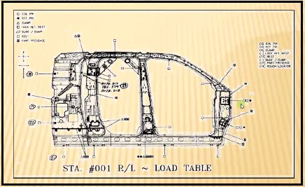
- Geometric dimensioning and tolerance (GT&D): - GD&T will be the part for which we need to design the fixture. It will provide information about locating pin, sequence of opening of clamps, rest, dump and slide stroke information.
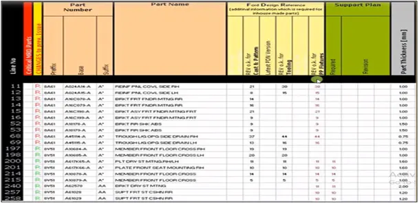
- Part list: - Part list will give us detailed information about the parts involved in the fixture. It will give us information like part name, part number, thickness of part, quantity of parts etc.
- CAD files: - CAD files of the parts give us information of 3D model, design analysis result. This information is very useful as it will give us an idea on starting to design a fixture.
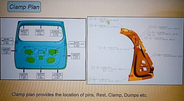
- Clamp plan: - Clamp plan is very important information as it will give us idea of places where we have our pins, clamps, dumps, rest, etc. We should never change the clamp position unless we ask the customer and they agree to it.
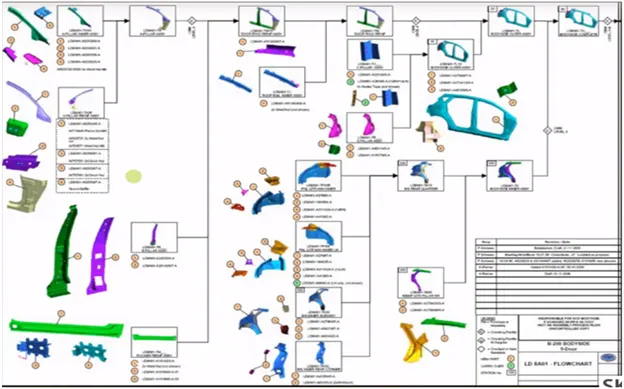
- Product assembly process sheets: - In product assembly process sheet, we will find what kind of products we are going to assemble for the particular unit or the component. The sequence of the assembly will also be given in this sheet.
4. What is clamp plan?
- A clamp is a device which is used to hold the work piece. It is a force actuating mechanism of the fixture.
- A clamp plan is a very important input from the customer, the clamp plan will give us information about area where the clamps will be fixed to ensure proper geometry of workpiece is maintained during the operation.
- Clamp plan provides information on location of pins, rest, clamps. dumps etc. The coordinates will also be mentioned in the clan plan. So, the design team can take the coordinates directly and start working on the fixture.
- We cannot change the clamp plan that is given by the customer. We have to inform the customer and if they agree then we can change it.
- What is the purpose of layout?
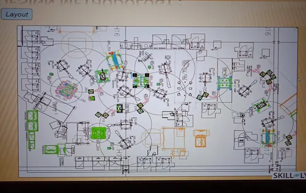
- Layout is the most effective arrangement of the machines, processing equipment, service department to achieve maximum efficiency of the 4 M (men, material, machine and method) in the plant.
- It will give the floor plan of how and where the machines will be placed, positions of the robots, storage racks, etc. It will also show the reachability of the robots to the fixture. Which is called as swept area of robot.
- Layout also provides information of flow of parts, station pitch, robot stations, tool changers, tip dressers, loading and unloading sequence.
- What is ERGO data?
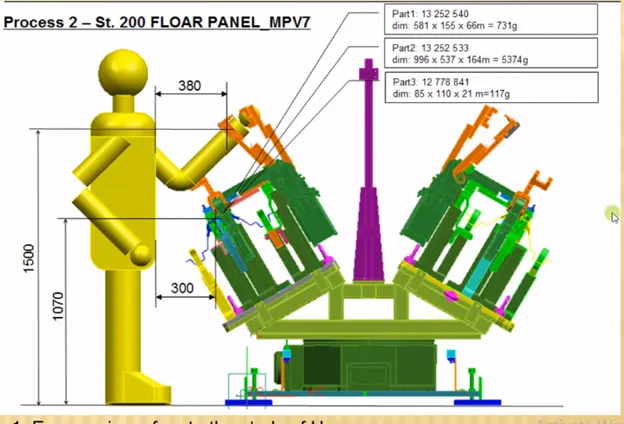
- Ergonomics is the application of psychological and physiological principles to the engineering and design of products, processes and systems. The goal of human factor is to reduce human errors, increase productivity and enhance safety and comfort with specific focus on interaction between human and rhing of interest.
- In any operation, the workers or operators at attain various postures, exerts force and work continuously in a cycle time to perform a particular task. This may cause high level of strain to the operators. To avoid the principle of ergonomics is applied in every operation wherever interaction of human with machine is involved.
- So, the ergo data is the input which gives human factors engineering data between operator and its working environment.
- It has various benefits like improved working conditions, reduce physical workload, improved work postures, reduce efforts of certain movements etc.
- What do you understand by weld study?
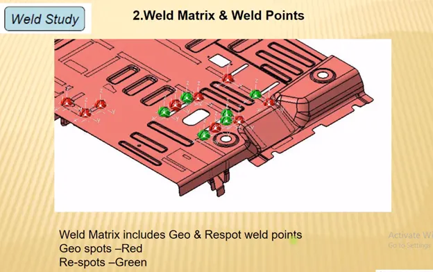
- Welding is a process which is widely used in automobile industry for joining of parts together. So, a welding fixture is necessary to be made so that the geometry of the part does not change during the welding process.
- Weld study includes study of gun and the weld matrix and weld points, geo spot and respot weld points.
- Weld gun study will give information about type of weld, temperature, type of current, approach of gun etc. weld matrix and the weld points will give us information on exactly where the welding will be done.
- There will be two welding stations, geo spots and respots. Geo spots will be the first round of welding operation. After this respot is done on the places where we could not weld in the geo spot station.
- What are the criteria for percentage calculation in designing stage? Explain it in details?
- Percentage completion criteria is the time period we assigned four different stages of the project and by analyzing this we will know how much our project is completed and which stages are behind the schedule. The percentage completion criteria is categorized as follows-
- 0 – 25% input and concept design: - We will get the inputs from the customer and by studying these inputs we will create a concept design of the fixture.
- 25 – 40% concept approval and simulation: - We will get the customers approval on the concept and we will also perform various simulations on the design.
- 40 – 85% design freezing and detailing: - Once the customer has agreed and approved on the design we will freeze the design and we will start with the 2D detailing of the parts. Once we have made all the parts, we will assemble the whole model.
- 85 – 100% check and final dispatch: - We will start the quality check on our fixture, then we will check the working of the fixture to see if it gives the intended output. Once all the checking work is done we will diassemble the assembly and pack it properly and dispatch it to the customer facility.
9. Brief about output in design?
- After the designing phase of a particular product, we not only make a 3D model, but we also have the simulation result perform on the model. We also make 2D detailed drawing sheets of all the parts that we have created, BOM, assembly sheets, etc. There are two types of tools-
- Utilized tool: - Utilized tools require two types of sheet that is key sheet and layout sheet. Key sheet shows the index, placement and location of particular units on tool base. Layout sheet is the detailed drawing of individual units to include all their component.
- Non-utilized tools: - Non-utilized tools are the tools like stands, tool Changers for which you don’t need the key sheet. It is the tools that can stand alone and can be detailed completely on the layout.
- What do you understand by structuring a design tree? How does it reduce errors during design process?
- Structuring a design tree is the process of naming all the assembly and parts in a systematic way and a specific standard, every customer has its own standard to structure design tree.
- If the parts or the assemblies are not named properly or it is not structured properly, then this will create a lot of confusion to understand the design.
- So, structuring our design tree is very important as it helps us to easily identify about the part or assembly belongs to which project. It can also help us to identify quantity of items of same type or different type used in assembly.
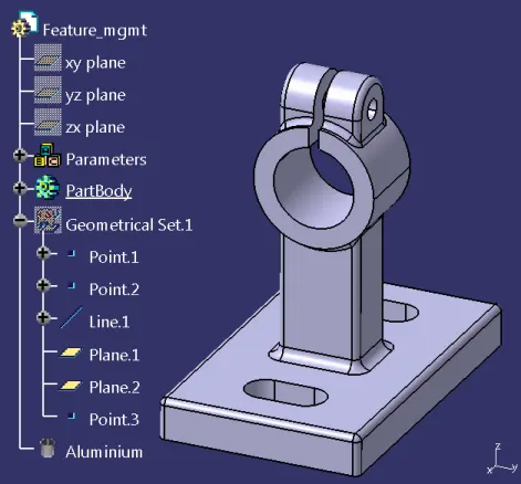
- From the above image we can see that the design parts are at the top and the standard parts are below.
- Blue highlighted number H1L – T9A – RRFRA – JG3 – 00 – 00 – 00, This is the product description or name.
- Here H1L- T9A is the project name, RRFRA is the panel name, JG3 is referring to the jig, number that is jig 3, 00 is the unit name, 00 is the part number, 00 is the component number.
- What are units? Mention 5 types of units?
- A unit is a device which has specific purpose, and is also part of a complex assembly. The BIW fixtures is assembly of many units. This units perform different functions. Units are off two types utilized and non-utilized tool.
- The units have specific function likes resting the panel, clamping the panel, locating the part, etc.
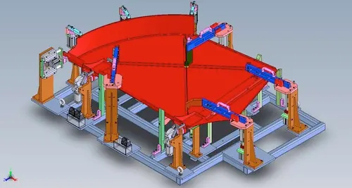
- The 5 types of units are
- Fixed pin unit – It is non-movable locating unit used for proper location of part and it arrests all the movement of past as well.
- Retract pin unit – It is movable locating pin unit which has retracting mechanism. This helps in ease of assembly of two components placed in different direction.
- Rough locator unit – It acts a rough guide so that the operator can mount the workpiece in proper place.
- Rest unit – Rest unit makes the panel rest on it.
- Base unit – It is unit on which all other units are mounted.
- Describe fixed pin units and their purpose?
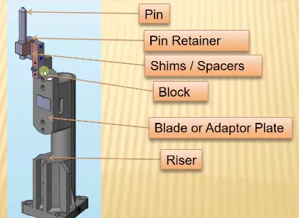
- Fixed pin unit is a non-movable locating unit used for proper location of part and it arrests all the movement of part as well. Fixed pin unit consist of pin, pin retainer, shims/spacer, block, blade or adaptor plate, riser. Riser is the part which is used to rise or increase the highest of the unit. Blades is mounted on the riser. Block will be mounted on the blade. Shims are small spacers which are used for stack up tolerance. Shims are made of various thickness like 0.1, 0.2, 0.5 mm etc. pin retainer will hold the pin and the pin is used to locate the part and restrict its motion.
- Purpose of fixed pin unit – The main purpose of the fixed pin unit is to locate the car panel and restrict its motion. It is placed following the 3-2-1 principle, so it is necessary to have two pins like 1 Pin will restrict 4 D.O.F. and the other pin must restrict 2 D.O.F.
- What are different parts of fixed unit?
- The different parts of fixed pin are as follows –
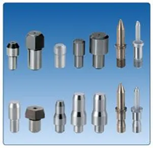
- Pin – pin or locating pin is used for location or positioning of workpiece in correct manner. This pin is made of precise dimension and tolerance. Usually two pins are enough to locate on a single plane. There are many types of locating pins available. It is up to us what kind o
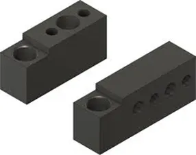
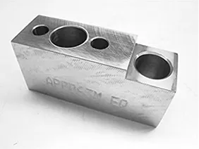
- Pin retainer – A pin retainer is a part which is used to hold the pin firmly and in position. A pin retainer can be a make part or a standard part also.
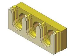
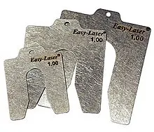
- Shims/spacer – Shims and spacers are plate of varying thickness which is used for compensation of stack up tolerance that is in assembly. The thickness of shims is 0.1mm, 02mm, 0.5mm, etc. sometimes in an assembly stack up tolerances is generated. This needs to be correct6ed so we use shims and spacers.
- Block – block can be machined to any thickness. This depends on the design of fixture and for what reason we want the block.
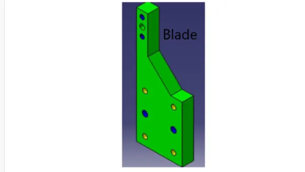
- Blade – Blades are plates attached to the risers, parts like cylinder arm etc. are mounted om the blade.
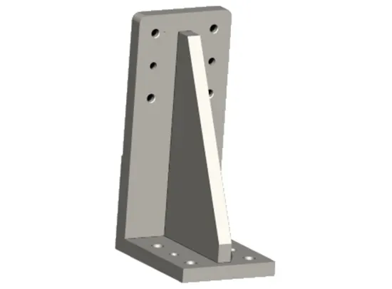
- Risers – Risers is a standard part which is used to rise up the height of whole unit. Risers are generally made of plate fabrication or plate and tube welding or form single gas cutting.
- What is the purpose of making rest unit and describe its parts?
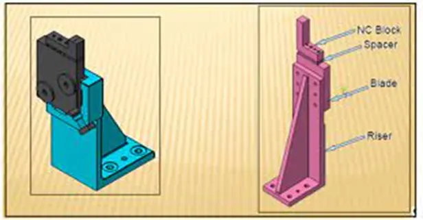
- Rest unit designed to support the car panel using Mylars, NC block. It is the simplest unit as it has only few parts like NC block, spacers/shims, blade, risers. Because of simplicity in design it is combined with other units to reduce the number of parts which will reduce cost. It can be combined unit so that it can clamp as well as rest the part, it can be combined with locating unit to locate as well as rest the part. The different parts of the rest unit are –
- NC block/Mylars – it is a part which is used to hold the panel from top and bottom. Mylars are of two kinds clamping Mylars and resting Mylars. Mylars have a jaw type shape, which improves the holding of part. Mylars are also known as fingers. It won’t allow the deformation of the part during the welding processes.
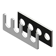
- Shims/spacers – Shims and spacers are plate of varying thickness which is used for compensation of stack up tolerance that is in assembly. The thickness of shims is 0.1mm, 02mm, 0.5mm, etc. sometimes in an assembly stack up tolerances is generated. This needs to be correct6ed so we use shims and spacers.
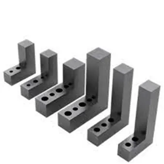
- Blade – Blades are plates attached to the risers, parts like cylinder arm etc. are mounted om the blade.
- Risers – Risers is a standard part which is used to rise up the height of whole unit. Risers are generally made of plate fabrication or plate and tube welding or form single gas cutting.
- What are the basic fundamentals to design a sensor unit?
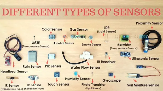
- Sensor is a device which detects or measures a physical property, and records, indicates or response to it. A unit which is designed to sense of object is called as sensor unit. The information from the sensor is sent to the PLC. A sensor is sensitive and can be damaged so a sensor cover is provided to it, there are different types of sensors like proximity sensor, laser sensor, infrared sensor, photoelectric sensor etc.
- Fundamental to designer sensor unit.
- Every single loose panel which is being welded by the tool should be sensed.
- Each panel should be sensed by one or two sensors depending upon size of panel.
- Every sensor should be mounted in a 3 directions adjustable way in general.
- What is rough locator unit and what is the basic fundamentals considered while designing it?
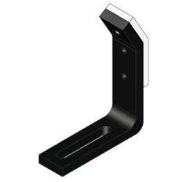
- Rough Locator is a device which is used to guide the workpiece in proper place. These rough locators is mainly used when manual operator is present, but it is also used in automation rocket are act as a fool proofing method.
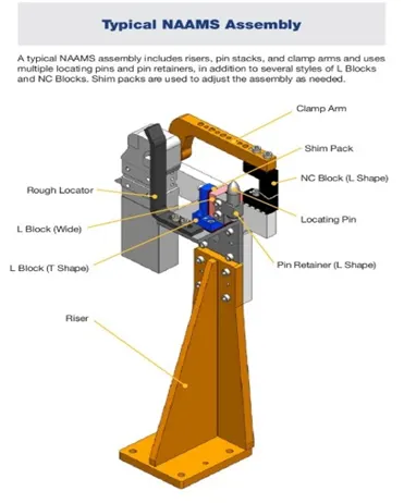
- Fundamentals considered while designing rough locators –
- Rough locators should be placed at edges of car panel, which it has to guide.
- They should be placed in same angle or car edge angle and minimum of 2-5mm distance should be maintained from edge of car panel.
- It should guide the panel in locating pins.
- Rough locator should start guiding the car panel before 10-15 mm from start of engagement.
- Rough locator should be designed with entry angle for car panel, which is generally 30-45 degree.
- The rough locator should be designed with two slots for easy adjustments.
- The slot should be in direction of car part guiding.
- What is a base unit and descried its parts?
- A 1base unit designed to mount all other units on it. It also mounts other tools like pneumatic valve box, trunking cable path etc. will be mounted on the base unit. The base unit can be firmly fixed to the ground or it can be a movable unit.
- Base unit parts are given below-
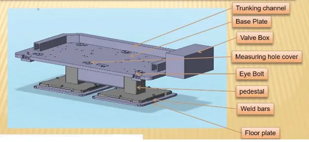
- Floor plate – Floor plate is used to mount entire base with floor. It also helps to achieve the flatness of the fixture.
- Weld bars and pedestal – Pedestal is a structure where entire unit of base will be mounted.
- Measuring hole cover – The base plate has several holes for mounting of units on it. These holes are measured by CMM machine to check if their position is accurate or not. A plate is used to cover the holes so that no dust or other particles can damage the whole.
- Valve box and trunking channel –Valve box supplies air to all the pneumatic cylinders in the assembly. A valve box consists of solenoid valve which is used to collect air from pneumatic cylinders to valve box.
- Base plate – A base plate is a heavy plate of large thickness because it carries weight of the entire assembly. It is machined to maintain parallelity and it also has holes drill on it to mount the units.
- What is a dump unit and what are its function?
- Dump unit is a complex unit which is used in planes where there is a space constraint or some other constraints. When we have some geometrical constraints and we cannot mount clamp unit, rest unit, etc. in a normal way then dump unit is used. It consists of dump cylinder to perform operation of clamping and unclamping of car panel.
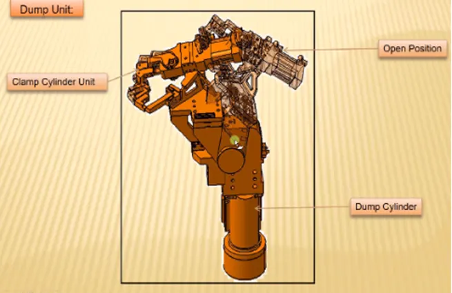
- Function of dump unit –
- When there is a particular constraint and we cannot assemble component in normal way. Dump unit is used.
- It has a dump cylinder which performs the opening and closing action. It has a clamp cylinder unit too.
- This dump Unit is complex in design and so it is used only in need.
- What is a slide unit? Mention where slide units are commonly used?
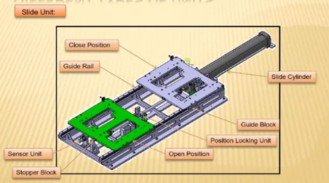
- Sliding units are positioning units which are used to position car part or panel, units, robots, for further operations. Sliding units are used in places where we have space constraint and different units cannot be used so we use sliding unit. It consists of full parts –
- Sliding cylinder – This is used to move the panel from open position to close position and vice versa.
- Position looking unit – It is used to lock the plate at a particular place and it will not allow it to move.
- Guide rail – It is used to guide the plate to move from one position to next.
- Stopper block – It is used to control the motion of sliding unit.
- Sensor units – it is used to sense whether the component is moving properly or not.