Week 3:- BiW Fixture Design Methodologies Challenges
Answer No.01
Design Methodology is a process to follow the pre designing stages of fixture design. We have four main design methodologies.
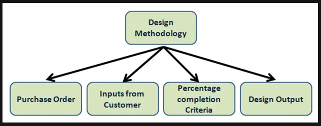
1) Purchase order: The purchase order is also known as PO. PO is an official document that buyers send to sellers to document the sale of products. In the purchase order we have a different types of information like,
- Price
- Brand details
- Delivery location and date
- Billing address
- Uses information
2) Inputs from customer: In every project the customer has its own requirementsand they give different inputs.
- Function requirements
- Standard components
- Layout ( flow of part and station pitch )
- Car body parts
- Ergo data ( its provide information of loading height )
- Design guidelines
- Weld study
3) Percentage completion criteria: In this we know how many days the project will take to complete.
- 00 - 25% input and concept design
- 25 - 40% approval and simulation
- 40 - 85% freezing and detailing
- 85 - 100% final dispatch
4) Design output: The design output is 3D models and 2D drawing. In this we have a key sheet and layout drawing sheets.
Answer No.02
The inputs required from the customer to start designing a fixture.
a) Functional requirements: What are the process tyhe fixture going to do, when we are taking requirements from the customer. depends on the design and raw material.
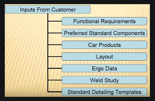
b) Preferred standard components: Every customer wants standard components. At the same time the different companies follow the different standards like, ABB, NAAMS and ZYTRAN.
c) Car products: Its provides information of locating pins, rest, clamp plan, part list and product assembly process sheet.
d) Layout: layout gives information related to flow of part, station pitch and robot station, tool changer, sub assembly links and last one loading unloading.
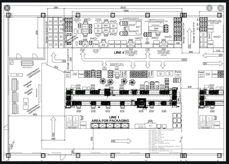
e) Ergo data: Refers to the study of human behavoir and movements. its provide information of loadind height.
f) Weld study: Weld study is matrix of Geo and Respot weld points.
g) Standard detailing templates: Every customer have their own detailing templates.
Answer No.03
The input we get from Car Products is,
a) Geometric dimensioning and tolerance: The GD& T provides thei nformation how to locate pins, clamp and rest information of each station.
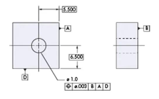
b) Part list: In this all about the part names, part numbers and part thickness. all these parts are going to be assembled in the fixture.
c) Clamp plan: Clamp plan is importent input from customer. The clamp position should not be changed without knowledge of customer.
d) Cad file: The cad file will be given from customer to develop a fixture design process.
e) Product assembly process sheet: The process sheet will provide all the information related to stage wise assembly and finished product.
Answer No.04
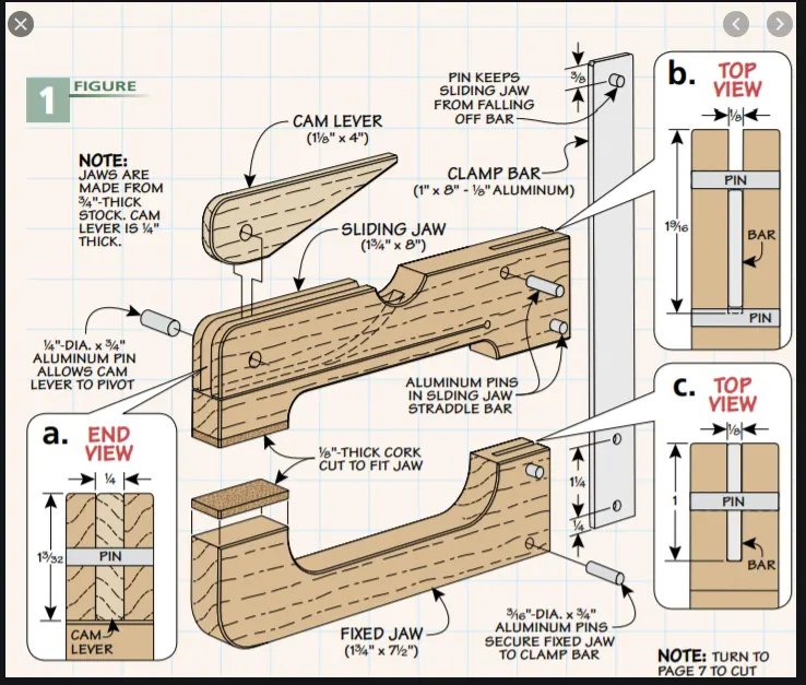
The clamp plan is to be hold or clamp car panel with NC blocks by using a clamp cylinder. Clamp plan is importent input from customer. The clamp position should not be changed without knowledge of customer.
Answer No.05
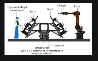
The basic purpose of a Layout is to understand the information about the production and where the fixture and robots are been placed. The layout shows entire assembly information to understand.
- flow of part
- station pitch
- robot station
- tool changer
- sub assembly links
- loading and unloading.
Answer No.06
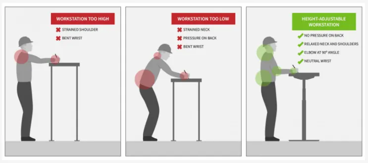
Ergo data is the inputs which gives human factor engineering data, between the operator and his working environment. The work place sutable for the worker.
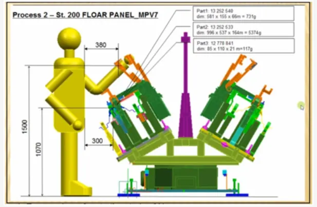
The ergo data improve working condition and reduce the work load. The basic study of ergo data is to be integration of human and machine.
Answer No.07
Weld study gives information about the weld gun, weld study matrix includes geo and respot weld points. We are doing number of weldings to tyhe particular body part or component.
The weld points is the points where the weld is going to happen. Geo weld ponits are welded in geo fixture and respot weld be done after the geo weld. Geo weld colour is in red and respot weld colour is in green or in multi colour.
Answer No.08
The percentage completion criteria in the designing stage is time plan which we define to complete the design.
- 00 - 25% input and concept design
It is the starting stage of the design where we will get all the design details from the customer, then the project design will start.
- 25 - 40% approval and simulation
Once project is designed then the project will send to customer for his approval. Once customer approval is done then it will go to simulation check.
- 40 - 85% freezing and detailing
In this freezing and detailing if we have any changes, the changes will done here and once again send to customer to his approval. Then after the freezing and detailing will done.
- 85 - 100% final dispatch
In this process the design will send to quality inspection then after dispatch to customer.
Answer No.09
The output of design is 3D models and 2D drawings of the tools. iIn this we have two types.
1) unitised tools: The unitised tools are like pin unit, clamp unit, rest unit. At the same time in this we have key sheets and layout sheets.
2) Non unitized tools: Non unitized tools are stand tools.
- Approved standard components
- Design must be as simple as possible
- Safety and ergonomic requirements
- Validate clamps and all weld guns
- Frames and structures are to be simple and study
Answer No.10
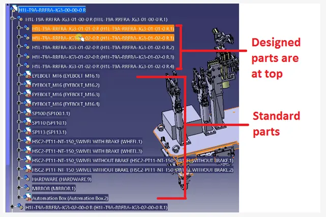
Structuring a design tree is a process where all the assemblies and parts names in specific starndand. In project design every customer have their own standards.
The parts which are designed by us should be place in top. The design tree will led to manufacturing the parts.
Answer No.11
While desinging the fixture we use different types of units. Units are part of the unitized tolls. We have two types of units.
1) Simple
- Rest unit
- Fixed pin unit
- Retract pin unit
- Rough locator unit
- Sensor unit
- Base unit
2) Complex unit
- Slide unit
- Dump unit
Answer No.12
The fixed pin unit ia a unit designed to locate the car panel using pins. The fixed pin unit have a riser, block, shims and blade.
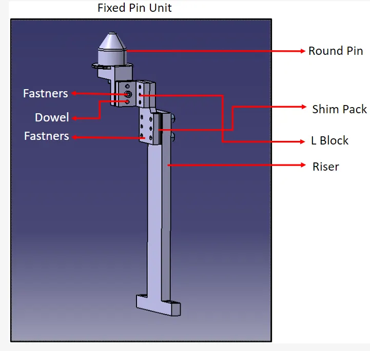
The purpose of fixed pin unit ishelp the parts to locate for welding operation. It is the part of the 3-2-1 principle. It restricts the 6 degrees of freedom.
Answer No.13
The different parts of a fixed unit are,
- Riser
- Blades
- Block
- Shims
- Pin retainer
- Locating pin
Answer No.14
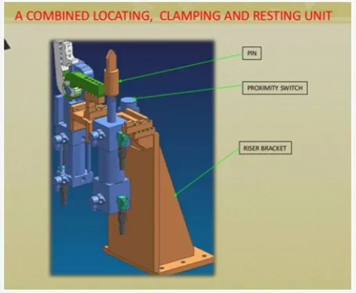
The purpose of making a Rest unit is to be support the car panel by using NC blocks, rest and mylar. It is the simple design and reduce the cost the project.
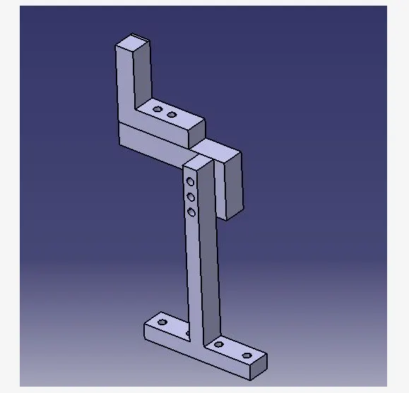
The main parts in the rest unit is Riser, blades, shims and mylars'
Riser: Riser is the stardand part which is used to rise up the height.
Blades: Blades also rise the heights. In this parts like cylinder, arms.
Shims: Shims are the thinkness plates, these are the small parts. the thinkness of part is 0.1mm,0.2mm and 0.3mm. The shims are used in one direction up and down to adject the height.
Mylars: Mylar is the components which is holds the car panel. In the we have two types top side mylars called as clamping mylars and the bottom side mylars called as resting mylars.
Answer No.15
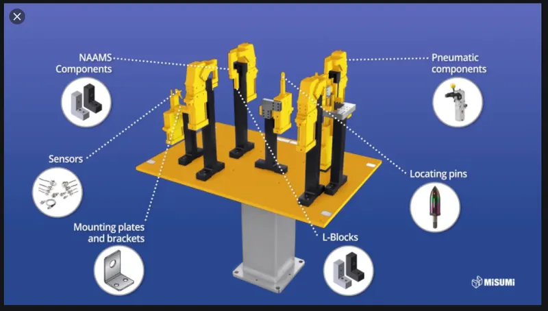
The basic fundamentals to design a Sensor unit is designed to be sense the car panel by using electrical sensors. The signals from the sensors will be fed to the PLC.
Fundamental of Sensor:
Every single loose panel which are being welded in a tool should be sended.
Every sensor should be mounted in a 3 direction adjustable way in general.
Types of sensors:
Proximity sensor
Laser sensor
Photo electric sensor
Answer No.16
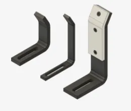
The rough locator unit is to be designed to guide the operator, to locate car panel on to the pins accordingly. Everu panel that we are going to assemble in that particular panel.
Fundamentals of rough locator:
Rough locators should be placed at the edges of the car panels, same angle ( 2 - 5 mm ) minimum distance.
It should guide the panel in pin arresting direction.
It should be designed with two slots to mount for easy adjustments.
Answer No.17
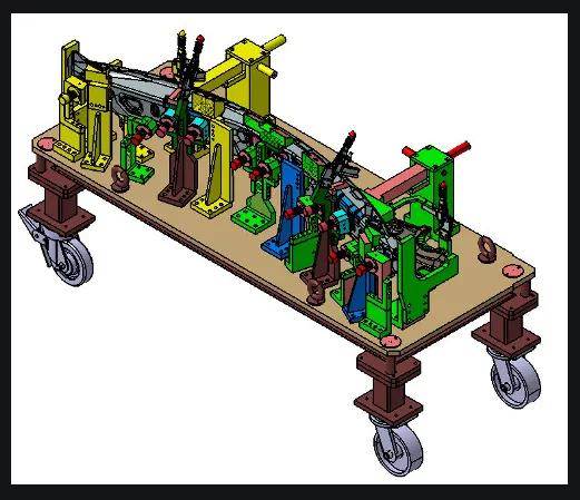
Base unit is designed to mount all the onther units of the tools. ( like other all units are clamp, pin, rest ). And aslo other parts necessary for a tool like vavle box, trunking cable path will also be mounted on to a base unit.
Base unit parts:
- Floor plate
- Weld bar
- Eyebolt
- Measuring hole cover
- Valve box
- Trunking cable path
- Floor panel
- Pedestal
Answer No.18
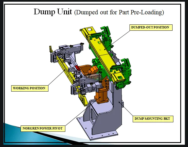
The dump unit is very complex unit to design. In the dump unit we have a less place to design. The dump unit is used to be operate the clampindg and unclamping the car panel.
Answer No.19
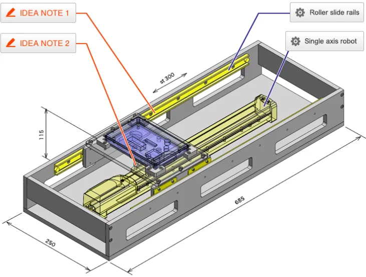
Slide unit is used to position the fixture, weld gun, units, robots into the futher operation.
Slide unit main parts:
- Close position
- Guide rail
- Slide cylinder
- Locking unit
- Sensor unit
- Stopper block.