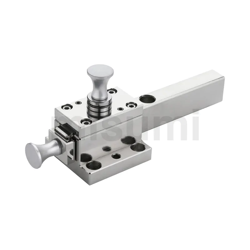
Week 3:- BiW Fixture Design Methodologies Challenges
| What is Design Methodology? |
Design methodology refers to a systematic approach or process used to guide the creation and development of a design solution. It provides a structured framework that designers follow to effectively and efficiently address design problems and achieve desired outcomes. Design methodology encompasses a range of activities, strategies, and techniques aimed at generating innovative, functional, and aesthetically pleasing designs. Here's an explanation of design methodology without plagiarism:
-
Problem Identification: The design methodology begins with identifying and understanding the problem or design challenge. This involves gathering information, conducting research, and analyzing user needs, constraints, and objectives. Clear problem definition is crucial for guiding the design process.
-
Research and Exploration: Designers engage in extensive research and exploration to gain insights, explore different possibilities, and generate ideas. They study existing designs, analyze market trends, explore materials and technologies, and seek inspiration from various sources. This research phase helps designers broaden their understanding and develop a foundation for their design concepts.
-
Concept Generation: Based on the insights gained from research, designers move into the concept generation phase. They brainstorm, sketch, and generate a variety of design concepts and solutions. This phase encourages creativity, encourages divergent thinking, and promotes the exploration of multiple design directions.
-
Concept Evaluation: After generating design concepts, designers evaluate and refine them against defined criteria and objectives. This evaluation involves considering factors such as feasibility, functionality, aesthetics, usability, sustainability, and manufacturability. Concepts may be further developed, combined, or eliminated based on the evaluation results.
-
Prototyping and Testing: Design methodology often involves building physical or digital prototypes to test and validate design concepts. Prototypes allow designers to evaluate the performance, functionality, and user experience of the design solution. Iterative prototyping and testing cycles help refine and improve the design based on feedback and user insights.
-
Detail Design and Development: Once a design concept is selected, designers move into the detail design and development phase. This involves refining the design, specifying materials, components, and dimensions, creating detailed technical drawings, and preparing documentation for production or implementation.
-
Production and Implementation: The final stage of design methodology focuses on the production or implementation of the design solution. This may involve coordinating with manufacturers, suppliers, or other stakeholders to ensure the design is realized according to specifications. Designers may also provide support during the production or implementation process to ensure the design's successful realization.
Throughout the design methodology, collaboration, communication, and iteration are essential elements. Designers often work in multidisciplinary teams, collaborating with experts from different fields to leverage diverse perspectives and expertise.
Design methodology provides a structured and systematic approach to the design process, enabling designers to navigate complexities, solve problems, and create innovative and functional design solutions that meet user needs and objectives.
2. What are the inputs required from the customer to start designing a Fixture?
To start designing a fixture, the following inputs are typically required from the customer:
-
Purpose and Requirements: A clear understanding of the purpose of the fixture and the specific requirements it needs to meet. This includes information on the intended use, desired functionality, and any specific features or constraints.
-
Product or Component Details: Detailed information about the product or component that the fixture will be designed to hold, support, or manipulate. This includes dimensions, weight, shape, material properties, and any special considerations.
-
Quantity and Production Environment: The expected quantity of fixtures needed and the production environment in which they will be used. This information helps in determining factors such as durability, repeatability, and ease of use.
-
Design Constraints: Any specific design constraints or limitations that need to be considered. For example, space limitations, compatibility with existing equipment or systems, ergonomic requirements, safety regulations, or industry standards.
-
Budget and Timeline: The customer's budget and desired timeline for the fixture design and manufacturing process. This information helps in determining the level of complexity, material choices, and feasibility of design iterations.
-
Sketches, Drawings, or Samples: Any available sketches, drawings, or physical samples of the product or component, as well as any existing fixture designs or concepts. These visual references provide valuable insights and help the designer understand the customer's expectations.
-
Communication and Collaboration: Effective communication channels and collaboration platforms to facilitate discussions, feedback, and updates during the design process. This ensures that the customer's input is incorporated and the design aligns with their expectations.
It is important to note that these inputs may vary depending on the complexity of the fixture and the specific industry or application. Working closely with the customer throughout the design process allows for iterative improvements and ensures the final fixture meets their requirements.
3. What is the input we get from "Car Products"?
When working with "Car Products," the following inputs are commonly obtained:
-
Product Specifications: Detailed specifications of the car product, such as its dimensions, weight, shape, and intended use. This information helps the designer understand the specific requirements and constraints that need to be considered during the design process.
-
Functional Requirements: Clear understanding of the product's intended functionality, including any specific features, components, or mechanisms that need to be incorporated. This includes aspects such as storage capacity, structural integrity, ease of installation, and compatibility with the car or related systems.
-
Material Preferences: Information about the preferred materials for the car product. Factors such as durability, strength, weight, and aesthetics play a crucial role in material selection. The customer's preferences, budget, and any industry or safety standards should be considered when choosing appropriate materials.
-
Existing Design or Reference: If the customer has an existing design or reference product, it can serve as a starting point for the new design. Any design files, drawings, or samples of similar car products can help the designer understand the desired style, functionality, or improvements the customer is seeking.
-
Branding and Aesthetics: Guidance on branding elements, including logos, colors, and visual style, that need to be incorporated into the car product. Maintaining brand consistency and aligning with the customer's visual identity is important for product coherence and market appeal.
-
Regulatory and Safety Standards: Awareness of any industry-specific regulations, safety standards, or certifications that the car product must meet. This ensures compliance with legal requirements and the safety of users.
-
Budget and Timeline: The customer's budgetary constraints and desired timeline for the product development and manufacturing process. This information helps the designer make appropriate decisions regarding design complexity, material choices, and feasibility of design iterations.
-
Market and Target Audience: Understanding the target market and audience for the car product is crucial. Factors such as consumer preferences, trends, and competition in the market help inform design decisions to create a product that meets customer needs and stands out in the market.
-
Communication and Feedback Channels: Establishing effective communication channels and feedback mechanisms to keep the customer informed and involved throughout the design process. Regular updates, design reviews, and opportunities for customer input ensure that the final car product aligns with their expectations.
These inputs may vary depending on the specific type of car product being designed, such as car accessories, interior components, exterior parts, or electronic systems. Gathering comprehensive input from the customer ensures that the designed car product meets their requirements, market demands, and industry standards.
4. What is the Clamp plan?
In the context of engineering or manufacturing, a "clamp plan" refers to a systematic approach or strategy for the proper use of clamps in a project or process. A clamp plan outlines the considerations, techniques, and procedures to ensure the effective and secure clamping of components or objects. Here are the key aspects typically included in a clamp plan:
-
Component Analysis: Understanding the components or objects to be clamped, their material properties, dimensions, and specific requirements. This analysis helps determine the appropriate clamping methods, forces, and types of clamps to be used.
-
Clamping Method Selection: Choosing the most suitable clamping methods based on the application, such as direct clamping, toggle clamping, vise clamping, or fixture clamping. The selection depends on factors like the shape, size, and accessibility of the components.
-
Clamp Type and Size: Selecting the appropriate clamp types and sizes based on the component analysis. Different clamp types include C-clamps, bar clamps, quick-action clamps, spring clamps, or custom-designed clamps. The sizes should be compatible with the dimensions of the components and provide adequate clamping force.
-
Clamping Sequence: Establishing the proper sequence for applying clamps to ensure stability and accuracy during the assembly or manufacturing process. The clamp plan outlines the order in which clamps should be positioned, tightened, and released to maintain alignment and prevent distortions.
-
Clamping Force Calculation: Determining the required clamping force to securely hold the components together without causing damage. Factors such as material properties, joint types, and external loads or vibrations are considered to calculate the appropriate force. This ensures proper clamping while avoiding excessive or insufficient pressure.
-
Safety Precautions: Incorporating safety measures to protect personnel and components during the clamping process. This includes providing proper training on clamp usage, using personal protective equipment, and considering potential risks such as pinch points, over-tightening, or releasing clamps safely.
-
Quality Control Checks: Defining inspection and verification procedures to ensure the quality and accuracy of clamping operations. Regular checks are performed to verify proper alignment, clamping force, and overall integrity of the clamped components. This helps identify and rectify any issues early on.
-
Documentation and Communication: Maintaining clear documentation of the clamp plan, including drawings, diagrams, or written instructions. Effective communication with the team members involved in the project ensures consistent understanding and adherence to the clamp plan.
A well-defined clamp plan helps streamline the clamping process, minimize errors, ensure proper alignment, and contribute to the overall efficiency and quality of the project or manufacturing operation.
5.What is the purpose of a Layout?
In fixture design, a layout serves the purpose of determining the spatial arrangement and configuration of components, features, and elements within the fixture. The layout provides a visual representation of how the various elements will be positioned and interconnected to achieve the desired functionality and effectiveness of the fixture. Here are the key purposes of a layout in fixture design:
-
Spatial Organization: The layout helps organize and allocate space within the fixture design. It ensures that all the required components, such as clamps, supports, guides, and locators, are appropriately placed to securely hold and position the workpiece or object being worked on. The layout helps optimize the use of available space and promotes efficient utilization of the fixture.
-
Interconnection and Compatibility: The layout identifies the interconnections and relationships between different components of the fixture. It ensures that the elements are positioned and aligned properly to work in harmony and achieve the desired functionality. The layout also considers compatibility with external systems or equipment, ensuring smooth integration and operation.
-
Accessibility and Ergonomics: A well-planned layout takes into account the accessibility and ease of use for operators or workers. It ensures that critical components or adjustment mechanisms are readily accessible for setup, loading, and unloading of workpieces. Ergonomic considerations in the layout help promote operator safety, comfort, and efficient workflow.
-
Clearances and Tolerances: The layout specifies the necessary clearances and tolerances between components to accommodate the workpiece and any required movements or operations. It ensures that there is sufficient space for the workpiece and any associated tooling or tool changes without interference or collisions.
-
Alignment and Precision: The layout facilitates precise alignment of the workpiece within the fixture. It defines the reference points, locating features, and alignment mechanisms to ensure accurate positioning and repeatability. The layout may include provisions for adjustment and fine-tuning to achieve the desired level of precision and alignment.
-
Visualization and Communication: The layout serves as a visual representation that helps communicate the fixture design concept to stakeholders, including designers, engineers, and clients. It aids in conveying the intended arrangement, functionality, and design intent, allowing for collaborative discussions, feedback, and improvements before the actual construction or fabrication of the fixture.
Overall, the purpose of a layout in fixture design is to provide a clear and comprehensive plan for the spatial arrangement, interconnection, and functionality of the fixture's components. It ensures optimal utilization of space, promotes efficient operations, enables precision, and facilitates effective communication throughout the fixture design process.
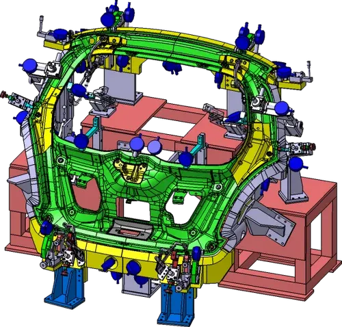
6. What is Ergo data?
In the context of ergonomics, "ergo data" refers to the collection and analysis of relevant data and information related to human factors, physical capabilities, and ergonomic considerations in the design and evaluation of products, systems, or work environments. Ergo data helps inform the design process by providing insights into human capabilities, limitations, and preferences to optimize usability, comfort, and safety. Here are some key aspects related to ergo data:
-
Anthropometric Data: Ergo data includes anthropometric measurements and data related to human body dimensions, sizes, and proportions. This data helps in designing products and workspaces that accommodate a wide range of users, ensuring appropriate fit, reach, and clearance for various body types.
-
Biomechanical Data: Ergo data also involves biomechanical measurements and data related to human movement, strength, and range of motion. This data helps assess the physical demands and stresses imposed on the human body during various tasks and activities. It guides the design of products and workstations that reduce the risk of musculoskeletal disorders and optimize ergonomics.
-
Strength and Force Data: Ergo data includes information about human strength capabilities, grip strength, force exertion, and lifting capacities. Understanding these factors helps determine appropriate force requirements, handle designs, and weight limits for products or equipment to prevent overexertion and fatigue.
-
Reach and Accessibility Data: Ergo data considers reach and accessibility measurements to ensure that controls, buttons, displays, or tools are within comfortable reach and visible to users. It helps establish optimal placement and positioning of components to minimize awkward postures or excessive reaching.
-
Posture and Movement Data: Ergo data involves studying and analyzing human posture, body movements, and repetitive tasks. This data helps identify potential ergonomic risks, such as awkward postures, repetitive motions, or prolonged static positions. It informs design decisions to promote neutral and comfortable body postures and minimize the risk of injuries or discomfort.
-
User Feedback and Surveys: Ergo data may include user feedback, surveys, or subjective assessments regarding comfort, usability, and satisfaction with a product, system, or workspace. This data provides insights into user preferences, perceptions, and areas of improvement to refine the design and enhance user experience.
-
Task Analysis: Ergo data involves detailed task analysis, which includes observing and documenting the physical requirements, steps, and durations of specific tasks. This data helps identify ergonomic challenges, workflow inefficiencies, and potential areas for optimization or automation.
By gathering and analyzing ergo data, designers and engineers can make informed decisions to create products, systems, or work environments that are more comfortable, safe, and efficient for users. Ergo data plays a crucial role in reducing the risk of injuries, improving productivity, and enhancing overall user satisfaction.

7. What do you understand by Weld study?
A "weld study" refers to the systematic examination and analysis of a welding process, joint design, or weldment to assess its quality, performance, and integrity. It involves evaluating various factors related to the welding operation, such as welding parameters, materials, joint configurations, and post-weld treatments. The primary goal of a weld study is to ensure that the weldments meet the required standards, specifications, and performance criteria. Here are some key aspects typically considered in a weld study:
-
Welding Process Evaluation: The study involves evaluating the welding process itself, which could be arc welding (such as MIG, TIG, or stick welding), resistance welding, or other methods. The study examines the suitability of the chosen process for the specific application, considering factors such as the material type, thickness, and joint configuration.
-
Welding Parameters: The weld study assesses the welding parameters used during the welding process, including current, voltage, travel speed, shielding gas flow rate, and electrode selection. The study aims to optimize these parameters to achieve desirable weld quality, such as proper penetration, fusion, and minimal defects like porosity or undercut.
-
Joint Design and Preparation: The weld study examines the joint design and preparation, including joint type, fit-up, bevel angles, root openings, and edge preparations. It ensures that the joint design is appropriate for the intended application and that it facilitates proper weld fusion and strength.
-
Material Considerations: The weld study takes into account the materials being welded, including their composition, thickness, and metallurgical properties. It considers factors such as material compatibility, heat-affected zone (HAZ) effects, distortion control, and the need for pre- or post-weld treatments like preheating or stress relieving.
-
Quality Control and Inspection: A crucial aspect of a weld study is implementing quality control and inspection techniques. This involves non-destructive testing (NDT) methods such as visual inspection, ultrasonic testing, X-ray examination, or dye penetrant inspection to assess weld quality, detect defects, and ensure compliance with relevant codes or standards.
-
Performance and Durability: The weld study evaluates the performance and durability of the weldment in the intended application. This includes analyzing factors such as load-bearing capacity, fatigue resistance, corrosion resistance, and environmental considerations to ensure the weldment meets the required specifications and can withstand the anticipated service conditions.
-
Documentation and Recordkeeping: A weld study typically involves documenting the weld procedure, welding parameters, inspection results, and any deviations or corrective actions taken during the study. This documentation serves as a reference for future production or maintenance activities and ensures traceability and accountability.
Overall, a weld study is conducted to assess the welding process, joint design, and weldments to ensure they meet quality standards, performance requirements, and industry or regulatory specifications. It helps identify areas for improvement, optimization, or corrective actions to enhance the overall weld quality and reliability.
8. What are the criteria for percentage completion in the designing stage? Explain it in detail.
The criteria for determining the percentage completion in the designing stage can vary depending on the specific project, industry, and organizational practices. However, some common criteria used to evaluate the progress and completion of the design stage include:
-
Conceptualization and Ideation: This criterion assesses the development of initial concepts, ideas, and design alternatives. It considers the generation and exploration of different design options, sketches, brainstorming sessions, and concept presentations. The percentage completion can be determined based on the number of concepts explored, their level of refinement, and the selection of a preferred concept.
-
Design Requirements and Specifications: The completion percentage can be based on the establishment and documentation of design requirements and specifications. This includes gathering client or user inputs, understanding functional needs, performance criteria, regulatory requirements, and any specific constraints. The percentage completion is determined by the clarity and completeness of the documented design requirements.
-
Preliminary Design Development: This criterion evaluates the progress in developing the preliminary design. It considers activities such as creating 2D or 3D models, generating layouts, performing calculations or simulations, and creating initial prototypes or mock-ups. The percentage completion can be based on the level of detail and fidelity achieved in the preliminary design development.
-
Design Review and Feedback Incorporation: The completion percentage can be determined based on the progress made in conducting design reviews and incorporating feedback. This includes presenting the design to stakeholders, receiving feedback, addressing concerns or suggestions, and making necessary design modifications or refinements. The percentage completion considers the number of design iterations completed and the incorporation of feedback from relevant parties.
-
Detailed Design Development: This criterion assesses the progress in developing the detailed design. It involves creating detailed engineering drawings, specifying material selections, tolerances, manufacturing processes, and assembly methods. The completion percentage can be determined by the extent to which the detailed design is developed, including the level of detail in the drawings, component specifications, and manufacturing considerations.
-
Design Validation and Analysis: This criterion evaluates the progress in performing design validation and analysis activities. It includes conducting simulations, stress analysis, prototyping, testing, and verification against design requirements. The completion percentage can be based on the completion of validation activities, the resolution of identified issues, and the achievement of desired performance criteria.
-
Design Documentation and Handover Preparation: This criterion considers the completion of design documentation and preparation for the handover to the next stage or team. It includes finalizing design reports, drawings, specifications, bills of materials, and any relevant documentation. The percentage completion can be determined based on the level of completeness and readiness of the design documentation.
It's important to note that the criteria for percentage completion in the design stage may vary depending on the project context and organizational practices. It is typically defined and agreed upon by the project team and stakeholders at the beginning of the project to ensure consistent evaluation and tracking of design progress.
9. Brief about "Output" in design?
In the context of design, "output" refers to the tangible or intangible deliverables or results that are generated as a result of the design process. It encompasses the final outcomes, artifacts, and documentation that communicate the design solution and enable its realization. Here's a brief overview of the concept of "output" in design:
-
Design Artifacts: Output in design often includes physical or digital artifacts that represent the design solution. These may include sketches, drawings, renderings, models, prototypes, or mock-ups. These artifacts help visualize and communicate the design concept, aesthetics, and functionality to stakeholders, clients, or production teams.
-
Design Documentation: Output in design also involves comprehensive documentation that provides detailed information about the design solution. This may include design specifications, technical drawings, bills of materials, manufacturing instructions, or assembly guidelines. The documentation ensures that the design can be accurately interpreted, implemented, and reproduced.
-
Design Presentations: Design output includes presentations or visual materials used to effectively communicate and pitch the design concept. This may involve slideshows, interactive presentations, or multimedia materials that highlight the design features, benefits, and potential impact. Design presentations help engage stakeholders, gather feedback, and generate support for the design solution.
-
Design Reports: Output in design can take the form of written reports that summarize the design process, research findings, design decisions, and rationale. These reports provide a comprehensive overview of the design solution, including its background, objectives, constraints, user research, and evaluation results. Design reports help stakeholders understand the design approach and support informed decision-making.
-
Design Guidelines or Standards: In some cases, design output includes the development of guidelines or standards that establish design principles, best practices, or criteria for future projects. These guidelines serve as a reference for designers, ensuring consistency, efficiency, and quality in subsequent design endeavors.
-
Design Files or Data: Output in design involves the creation and organization of design files or data that represent the design solution in a digital format. This may include CAD (Computer-Aided Design) files, 3D models, design databases, or design specifications stored in electronic formats. Design files enable efficient collaboration, revision control, and future modifications.
-
Design Deliverables: Finally, output in design comprises any specific deliverables agreed upon between the design team and clients or stakeholders. These deliverables can vary depending on the project scope and context. They may include design iterations, design options, user interface designs, branding materials, packaging designs, or any other design-specific outcomes.
The design output serves as the culmination of the design process, capturing the design solution in a tangible form that can be shared, reviewed, evaluated, and implemented. It plays a crucial role in effectively communicating the design intent, enabling collaboration, facilitating decision-making, and supporting the realization of the design solution.
10. What do you understand by structuring a design tree? How does it reduce errors during the design process?
Structuring a design tree refers to the organization and hierarchical arrangement of design elements, components, or subassemblies in a systematic and logical manner. It involves creating a visual representation or a hierarchical structure that captures the relationships and dependencies between various design entities. Here's an explanation of how structuring a design tree helps reduce errors during the design process:
-
Visual Clarity and Understanding: A well-structured design tree provides a clear visual representation of the design hierarchy and relationships. It helps designers understand the overall structure of the design and how different components or subassemblies are connected. This clarity aids in identifying potential errors or inconsistencies early in the design process.
-
Design Decomposition and Modularity: Structuring a design tree allows for the decomposition of complex designs into smaller, more manageable components or subassemblies. By breaking down the design into modular units, it becomes easier to analyze, validate, and troubleshoot individual components or subassemblies, reducing the likelihood of errors propagating throughout the entire design.
-
Dependency Management: The hierarchical structure of a design tree captures the dependencies between different design elements. It helps ensure that changes made to one component or subassembly are correctly reflected in related elements. By managing and tracking these dependencies, errors due to inconsistent or outdated information can be minimized, preventing design inconsistencies and issues during manufacturing or assembly.
-
Design Revision Control: A structured design tree facilitates efficient revision control and version management. Each design element or component can be tracked and versioned, allowing designers to revert to previous versions if errors or issues arise. This helps in maintaining a record of design changes, ensuring traceability, and enabling error correction while minimizing the risk of introducing new errors.
-
Design Validation and Verification: A design tree structure allows for systematic design validation and verification processes. Design elements or subassemblies can be individually analyzed and verified for their performance, functionality, and compatibility with other components. This approach helps catch errors or design conflicts early on, enabling timely corrections and reducing the likelihood of costly errors during the manufacturing or assembly stages.
-
Collaboration and Communication: A well-structured design tree promotes effective collaboration and communication among design team members and stakeholders. It provides a common framework for discussing and reviewing the design, making it easier to communicate design changes, modifications, or clarifications. This reduces the chances of misinterpretation or miscommunication, leading to fewer errors caused by misunderstandings.
-
Error Localization and Troubleshooting: In the event of an error or issue in the design, a structured design tree aids in localizing and isolating the problem to specific components or subassemblies. This targeted approach simplifies the troubleshooting process, allowing designers to focus on the specific area where the error occurred and facilitating prompt resolution.
By structuring a design tree, designers can enhance their understanding of the design, manage dependencies, track revisions, validate components, and facilitate effective collaboration. These benefits contribute to reducing errors and ensuring a more efficient and error-free design process.
11. What are Units? Mention 5 types of units.
In the context of fixture design, "units" refer to the individual components or elements that make up the fixture. These units are designed and assembled together to create a functional and purposeful fixture. Here are five types of units commonly used in fixture design:
-
Base Unit: The base unit forms the foundation or support structure of the fixture. It provides stability, rigidity, and a solid platform for mounting other components. The base unit is typically designed to withstand the loads, forces, and vibrations associated with the fixture's intended use.
-
Clamping Unit: The clamping unit is responsible for securely holding and positioning the workpiece or object within the fixture. It includes components such as clamps, vises, or holding devices that provide the necessary grip and immobilization. The clamping unit ensures that the workpiece remains stable during machining, assembly, or inspection processes.
-
Guiding Unit: The guiding unit consists of components that guide the movement of tools, workpieces, or other elements within the fixture. It includes features such as guide rails, guide blocks, or linear motion systems that facilitate precise and controlled movement along specified paths. The guiding unit ensures accurate positioning and alignment during various operations.
-
Locating Unit: The locating unit is responsible for establishing the reference points or positions of the workpiece within the fixture. It includes features such as locating pins, holes, or surfaces that ensure consistent and repeatable positioning of the workpiece. The locating unit aids in achieving precise alignment, orientation, and dimensional accuracy during machining or assembly processes.
-
Support Unit: The support unit provides additional support or reinforcement to the fixture structure or specific components. It includes elements such as braces, brackets, or support arms that enhance stability, load-bearing capacity, or vibration damping. The support unit helps maintain the structural integrity and performance of the fixture under varying loads and conditions.
These different units in fixture design work together to create a robust, functional, and efficient fixture system. They are designed to meet the specific requirements of the workpiece, manufacturing process, or inspection procedure. Each unit plays a critical role in ensuring accurate positioning, secure clamping, controlled movement, and reliable support, thereby enabling the successful execution of the intended operations.
12. Describe Fixed Pin units & their purpose?
Fixed pin units are a type of component commonly used in fixture design. These units consist of fixed pins that are strategically positioned within a fixture to serve specific purposes. Here is a description of fixed pin units and their purposes:
Fixed Pin Units: Fixed pin units are designed to hold and locate workpieces or objects within a fixture. They typically consist of cylindrical pins that are securely mounted in predetermined positions within the fixture structure. The fixed pins are rigidly attached and cannot be adjusted or moved during the operation of the fixture.
Purpose of Fixed Pin Units:
-
Workpiece Alignment: Fixed pin units play a crucial role in aligning workpieces accurately within the fixture. The pins are strategically positioned to engage with specific features or reference points on the workpiece, ensuring precise alignment in terms of orientation, position, or angle. This alignment is essential for consistent and accurate machining, assembly, or inspection processes.
-
Locating and Indexing: Fixed pin units serve as locating devices to establish reference positions or points on the workpiece. By engaging with corresponding holes, slots, or other features on the workpiece, the fixed pins provide a reliable and repeatable method of positioning the workpiece within the fixture. This allows for consistent and repeatable setups, minimizing errors and ensuring consistent quality.
-
Workpiece Stability: Fixed pin units contribute to the stability and immobilization of the workpiece during machining, assembly, or inspection operations. The pins prevent undesired movement, shifting, or rotation of the workpiece within the fixture, ensuring that the desired features or areas remain accessible and positioned correctly.
-
Support and Load Distribution: In certain cases, fixed pin units may also provide additional support or distribute loads on the workpiece. By engaging with specific areas, the pins can help distribute forces or loads evenly, preventing distortion, deformation, or damage to the workpiece. This is particularly important when working with delicate or sensitive components.
-
Facilitating Workflow: Fixed pin units also aid in streamlining the workflow and setup processes in a fixture. By providing fixed and reliable reference points, they simplify and expedite the positioning of workpieces within the fixture. This improves overall productivity, reduces setup time, and ensures consistent and efficient operations.
Overall, fixed pin units are integral components in fixture design, serving to align, locate, stabilize, and support workpieces. They contribute to the precision, accuracy, and repeatability of machining, assembly, or inspection processes by establishing reliable reference points and maintaining the desired workpiece positions within the fixture.
13. What are the different parts of a fixed unit?
A fixed unit, also known as a stationary clamp or fixed clamp, is a device used in various applications to securely hold and position workpieces within a fixture. While the specific design and components can vary depending on the application and manufacturer, here are the different parts commonly found in a fixed unit:
-
Clamp Body: The clamp body is the main structural component of the fixed unit. It provides the framework and housing for the other components. The clamp body is typically made of a sturdy material such as steel or aluminum to ensure strength and rigidity.
-
Clamping Arm: The clamping arm is a movable component attached to the clamp body. It is responsible for applying the clamping force to hold the workpiece in place. The clamping arm can be adjusted or locked into position to achieve the desired clamping pressure.
-
Clamp Pad/Jaw: The clamp pad or jaw is the part of the fixed unit that comes into direct contact with the workpiece. It is designed to grip the workpiece securely without causing damage or deformation. The clamp pad may have a smooth surface, serrated teeth, or specialized gripping elements depending on the application and workpiece requirements.
-
Mounting/Base Plate: The mounting or base plate provides the interface between the fixed unit and the fixture or workbench. It is typically attached to the clamp body and allows for secure mounting of the fixed unit to the fixture. The mounting plate may have holes or slots for bolts, screws, or other fasteners for attachment.
-
Fasteners: Fasteners such as bolts, screws, or clamping knobs are used to secure and tighten the different parts of the fixed unit. These fasteners ensure that the clamp body, clamping arm, clamp pad, and mounting plate are held together securely, providing stability and maintaining the clamping force.
-
Adjustment Mechanism: Some fixed units feature an adjustment mechanism that allows for fine-tuning of the clamping force or position of the clamping arm. This mechanism can be in the form of a threaded screw, a cam lever, or other mechanisms that provide controlled and precise adjustments.
-
Locking Mechanism: To secure the clamping arm in position and prevent unintentional movement or release of the workpiece, a locking mechanism is often incorporated. This mechanism can be a lever, a ratcheting mechanism, or other means of locking the clamping arm in place.
It's important to note that the specific design and components of a fixed unit can vary depending on the intended application, industry, and manufacturer. However, the aforementioned parts represent the fundamental components commonly found in fixed units used for clamping and securing workpieces in a wide range of fixtures and setups.
14. What is the purpose of making a Rest unit & describe its parts?
A rest unit is a component used in fixture design to provide support and stability to a workpiece during machining, assembly, or inspection processes. Its primary purpose is to prevent the workpiece from sagging, bending, or deforming under its own weight or the forces applied during the operation. Here is an explanation of the purpose of a rest unit and its main parts:
Purpose of a Rest Unit:
-
Support: The main purpose of a rest unit is to provide support to the workpiece. It helps distribute the weight of the workpiece evenly, preventing sagging or deformation that could compromise the accuracy or quality of the operation. The rest unit ensures that the workpiece remains stable and properly positioned throughout the process.
-
Stability: By offering a stable base, a rest unit helps minimize vibrations and unwanted movements of the workpiece. This stability is crucial for achieving precise and consistent results during machining or assembly operations. It reduces the risk of errors and ensures that the workpiece remains securely in place.
-
Accessibility: A rest unit facilitates easy access to the workpiece from multiple angles. It allows operators or machines to approach the workpiece without obstruction, enabling efficient and effective operations. This accessibility is particularly important when working on complex or intricate parts that require precise positioning and manipulation.
Parts of a Rest Unit:
-
Rest Body: The rest body is the main structural component of the rest unit. It provides a stable foundation and support for the workpiece. The rest body is typically designed to be rigid and durable, capable of withstanding the forces exerted during the operation.
-
Support Surface: The support surface is the part of the rest unit that comes into contact with the workpiece. It is usually flat or contoured to match the shape of the workpiece, ensuring optimal contact and support. The support surface may incorporate features such as grooves, ridges, or anti-slip materials to enhance grip and prevent movement.
-
Mounting/Base: The mounting or base of the rest unit provides a means for attaching it to the fixture or workbench. It is usually designed with mounting holes, slots, or other provisions to allow secure installation and adjustment of the rest unit's position.
-
Adjustability Mechanism: Some rest units include an adjustability mechanism to accommodate workpieces of different sizes or shapes. This mechanism allows the rest unit to be adjusted vertically or horizontally to match the specific requirements of the workpiece and operation. It enables versatility and adaptability in supporting various workpiece configurations.
-
Locking Mechanism: To ensure that the rest unit remains securely in place during the operation, a locking mechanism may be incorporated. This mechanism can be in the form of clamps, bolts, or other locking devices that prevent unintended movement or displacement of the rest unit.
The design and configuration of rest units can vary depending on the specific application and requirements. However, the core purpose remains consistent: to provide stable support and prevent deformation or movement of the workpiece. By utilizing a rest unit, the fixture design ensures that the workpiece remains properly positioned, accessible, and stable throughout the machining, assembly, or inspection process.
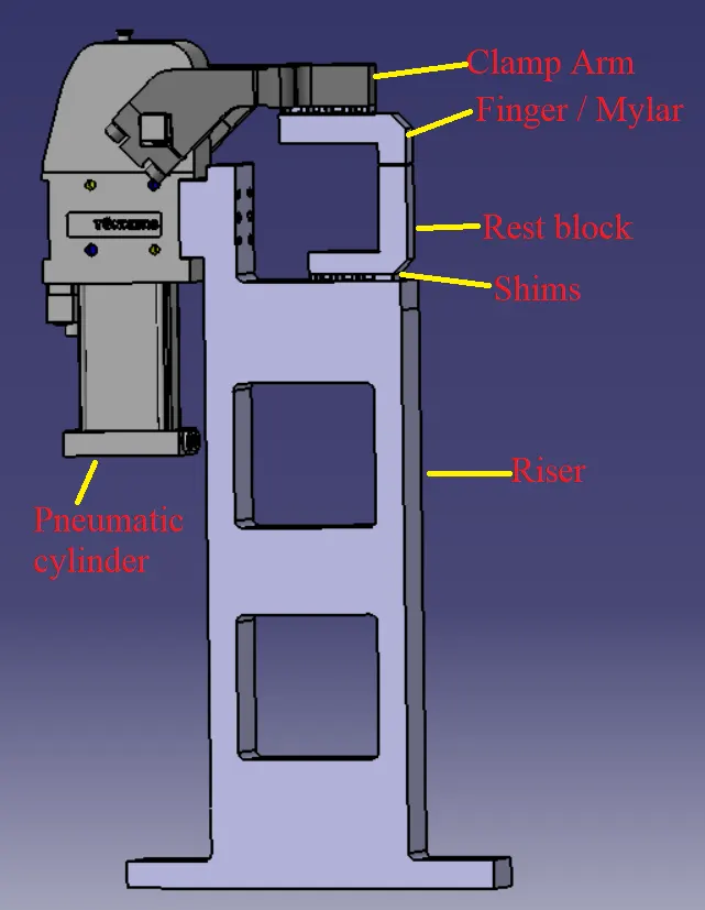
15.What are the basic fundamentals to design a Sensor unit?
Designing a sensor unit in fixture design involves considering several fundamental factors to ensure its effective integration and functionality within the fixture system. Here are some basic fundamentals to consider when designing a sensor unit specifically for fixture design:
-
Measurement Requirement: Determine the specific measurement requirement for the fixture. Identify the parameter you need to measure, such as position, force, pressure, or temperature. Consider the desired accuracy, range, and resolution of the measurement.
-
Sensor Selection: Select a sensor that is suitable for the measurement requirement and compatible with the fixture system. Consider factors such as sensor type (e.g., proximity sensor, load cell, temperature sensor), measurement principle, range, sensitivity, response time, and environmental compatibility.
-
Mounting and Positioning: Determine the optimal location and mounting method for the sensor unit within the fixture. Consider the sensor's physical dimensions, mounting requirements, and the need for precise positioning relative to the workpiece or other fixture components.
-
Mechanical Integration: Ensure proper mechanical integration of the sensor unit into the fixture design. Consider factors such as mounting brackets, fixtures, or adapters needed to securely hold and align the sensor unit within the fixture structure. Ensure that the sensor's position is stable and accurately aligned with the measurement target.
-
Electrical Connections: Determine the electrical connections required for the sensor unit. Consider the power supply requirements, signal output format (analog or digital), and any additional electrical interfaces needed for communication or data acquisition. Ensure proper cable routing, shielding, and grounding to minimize noise and interference.
-
Signal Conditioning: Evaluate if the sensor's output requires signal conditioning to enhance accuracy or compatibility with the fixture system. Depending on the sensor type, you may need amplification, filtering, linearization, or calibration circuitry to process and adapt the sensor signal for optimal use within the fixture system.
-
Environmental Considerations: Assess the operating environment of the fixture system and its potential impact on the sensor unit. Consider factors such as temperature, humidity, vibration, and exposure to contaminants. Choose a sensor that can withstand the environmental conditions or implement protective measures, such as enclosures or sealing, to ensure reliable and accurate measurements.
-
Integration with Control System: Determine how the sensor unit will integrate with the control system or data acquisition system of the fixture. Consider the compatibility of the sensor's output with the control system inputs and the necessary interfaces or protocols for data transfer. Ensure that the control system can accurately interpret and utilize the sensor data for process control or feedback.
-
Testing and Calibration: Plan for the testing and calibration of the sensor unit within the fixture system. Develop procedures for sensor calibration against known standards or reference measurements. Consider the frequency of calibration, any in-situ calibration requirements, and methods for validating the sensor's performance and accuracy within the fixture system.
By considering these basic fundamentals, you can design a sensor unit that effectively integrates into the fixture system, provides accurate measurements, and contributes to the overall functionality and performance of the fixture design.
16. What is a Rough locator unit & what are the basic fundamentals to consider while designing it?
A rough locator unit in fixture design is a component used to position and align workpieces within a fixture during the initial stages of the manufacturing process. It helps establish a rough reference point or orientation for the workpiece, allowing for subsequent operations to be performed accurately. Here are the basic fundamentals to consider when designing a rough locator unit in fixture design:
-
Workpiece Constraints: Understand the specific constraints and requirements of the workpiece. Consider factors such as its shape, dimensions, and the critical features that need to be located and aligned. Analyze the tolerances and permissible variations in the workpiece dimensions to determine the level of precision required in the rough locator unit design.
-
Locating Points: Identify the key points on the workpiece that will be used for rough positioning and alignment. These points should provide sufficient stability and guidance for subsequent operations. Typically, three or more locating points are used to establish a stable reference frame.
-
Locating Elements: Select appropriate locating elements that will engage with the workpiece to establish the desired positioning and alignment. Common locating elements include pins, pads, or surfaces with specific contours or profiles that match corresponding features on the workpiece. Consider factors such as the material, shape, size, and location of the locating elements.
-
Locating Mechanism: Determine the mechanism used to engage and disengage the locating elements with the workpiece. This mechanism should allow for easy insertion and removal of the workpiece while ensuring a secure and stable connection during operation. Consider mechanisms such as manual clamping, spring-loaded mechanisms, or pneumatic/hydraulic systems based on the specific requirements of the fixture design.
-
Stability and Rigidity: Ensure that the rough locator unit is designed to provide sufficient stability and rigidity to hold the workpiece securely during rough positioning. Consider factors such as the material selection, structural design, and reinforcements to minimize any movement or deflection during operation.
-
Compatibility with Fixture: Ensure that the rough locator unit is compatible with the overall fixture design and can be easily integrated. Consider factors such as the available space within the fixture, mounting options, and any necessary adjustments or accommodations required for proper alignment and positioning.
-
Clearances and Interference: Account for any necessary clearances and avoid interference between the rough locator unit and other fixture components or tooling. Ensure that the rough locator unit does not obstruct the subsequent operations or hinder access to critical areas of the workpiece.
-
Ease of Use and Maintenance: Design the rough locator unit to be user-friendly and easy to operate. Consider factors such as ergonomics, accessibility for loading and unloading the workpiece, and any provisions for adjustment or maintenance of the rough locator unit itself.
-
Documentation and Standardization: Document the design details and specifications of the rough locator unit for future reference and replication. Consider standardizing the rough locator unit design across similar workpieces or processes to streamline production and ensure consistency.
By considering these fundamental aspects, you can design a rough locator unit that effectively positions and aligns workpieces within a fixture, providing a reliable and repeatable reference for subsequent manufacturing operations.
17. What is a Base unit and describe it's parts?
In fixture design, a base unit refers to the foundational component of a fixture system that provides support, stability, and the structural framework for holding and positioning workpieces. It serves as the starting point for building the entire fixture assembly. Here is a description of the basic parts typically found in a base unit:
-
Base Plate: The base plate is a flat, rigid component that forms the bottom surface of the fixture. It provides a stable foundation and support for the entire fixture assembly. The base plate is often made of materials such as steel, cast iron, or aluminum to ensure durability and dimensional stability.
-
T-Slots or Keyways: T-slots or keyways are milled or extruded slots integrated into the base plate. These slots are used to secure and position fixture components such as clamps, locators, or other workholding elements. They enable easy adjustment and reconfigurability of the fixture by allowing various components to be mounted and positioned along the slots.
-
Mounting Holes: The base unit typically features pre-drilled or tapped holes that allow it to be securely mounted to a workbench, machine table, or other supporting structures. These mounting holes facilitate proper alignment and attachment of the base unit to ensure stability during operation.
-
Alignment Pins or Dowels: Alignment pins or dowels are often incorporated into the base unit to provide accurate and repeatable positioning of the fixture assembly. These pins ensure precise alignment between the base unit and other fixture components, such as subplates, modular units, or tooling nests.
-
Guideways or Rails: In some cases, base units may include guideways or rails that allow for linear or sliding motion of fixture components. These guideways enable the adjustment of certain fixture elements to accommodate different workpiece sizes or configurations. They ensure proper alignment and movement control within the fixture assembly.
-
Leveling Mechanism: To compensate for uneven surfaces or to achieve precise leveling, a base unit may incorporate a leveling mechanism. This mechanism typically includes adjustable feet or screws that allow for fine-tuning and leveling of the fixture assembly to ensure proper alignment and stability during operation.
-
Riser Blocks or Shims: Riser blocks or shims may be used in the base unit to raise or elevate certain components to the desired height. These blocks or shims are positioned between the base plate and other fixture elements to compensate for variations in workpiece dimensions or to align specific features of the workpiece with the tooling or machining elements.
-
Structural Supports: Depending on the complexity and size of the fixture assembly, additional structural supports such as columns or braces may be incorporated into the base unit. These supports provide added rigidity, strength, and stability to the fixture assembly, particularly for larger or more intricate fixtures.
The specific design and configuration of the base unit may vary depending on the requirements of the fixture application, the type of workpiece being held, and the machining or assembly processes involved. However, the primary function of the base unit remains consistent—to provide a solid foundation, structural support, and proper alignment for the entire fixture system.
18. What is a Dump Unit and what are its functions?
In the context of fixture design, a dump unit is a specialized component used to unload or remove finished or processed workpieces from a fixture or machine. Its primary function is to facilitate the safe and efficient ejection or disposal of workpieces after the completion of a manufacturing or assembly process. Here is an explanation of the dump unit's purpose and functions:
-
Workpiece Discharge: The main function of a dump unit is to provide a mechanism for discharging or removing workpieces from the fixture. It is designed to handle the release and controlled movement of the workpiece to a designated area or conveyor system for further processing or packaging.
-
Ejection Mechanism: A dump unit incorporates an ejection mechanism that performs the physical action of pushing or releasing the workpiece from its fixed position within the fixture. This mechanism can be pneumatic, hydraulic, mechanical, or a combination thereof, depending on the specific requirements of the application.
-
Controlled Release: The dump unit ensures that the ejection or release of the workpiece is controlled and precise. It allows for the workpiece to be discharged smoothly and without causing damage or misalignment.
-
Safety and Protection: The dump unit is designed with safety considerations in mind. It aims to protect both the workpiece and the operators from any potential hazards during the unloading process. Safety features such as sensors, interlocks, or guards may be integrated into the dump unit to ensure safe and reliable operation.
-
Workpiece Orientation: In some cases, the dump unit may also be responsible for controlling the orientation of the workpiece during ejection. It can be designed to rotate, tilt, or position the workpiece in a specific manner to facilitate its proper alignment with downstream processes or to ensure it falls into the desired container or collection area.
-
Integration with Conveyor or Handling Systems: Dump units are often designed to seamlessly integrate with conveyor systems or other handling equipment. They ensure a smooth transition of the workpiece from the fixture to the subsequent stages of the production line, such as sorting, inspection, packaging, or further machining.
-
Customizability: Dump units can be customized to suit specific application requirements. This includes considerations such as the size and weight of the workpiece, the desired speed and force of ejection, and compatibility with the overall fixture and production setup.
-
Maintenance and Reliability: Dump units should be designed for ease of maintenance and reliability. They should have accessible components for inspection, cleaning, and potential repair or replacement. Additionally, the dump unit's design should consider factors such as wear and tear, lubrication requirements, and any necessary preventive maintenance procedures.
By incorporating a dump unit into the fixture design, manufacturers can automate the unloading process, improve production efficiency, and ensure the safe handling of finished workpieces.
19. What is a Slide unit? Mention where Slide units are commonly used.
In fixture design, a slide unit refers to a component that allows linear movement or sliding motion of a workpiece or fixture element within the fixture system. It enables precise positioning, adjustment, or transfer of the workpiece or tooling along a defined path. Slide units are commonly used in various industries and applications where controlled linear motion is required. Here are some areas where slide units are commonly utilized:
-
Assembly and Manufacturing Processes: Slide units find extensive use in assembly lines and manufacturing processes where precise movement and positioning of workpieces or tooling are crucial. They enable the smooth transfer of components between workstations, alignment of parts during assembly, and controlled movement of fixtures or cutting tools during machining operations.
-
Inspection and Quality Control: Slide units are employed in inspection and quality control processes to facilitate the movement of workpieces or measuring devices for accurate dimensional checks, gauging, or testing. They ensure that workpieces are positioned correctly under inspection equipment, allowing for efficient and reliable quality control procedures.
-
Material Handling and Conveying Systems: Slide units play a vital role in material handling and conveying systems. They enable the controlled transfer of goods, parts, or components along production lines, conveyor belts, or automated systems. Slide units ensure smooth movement and accurate positioning of items during loading, unloading, sorting, or packaging operations.
-
Packaging and Labeling: In packaging applications, slide units are utilized to move packages or containers through different stages of the packaging process. They allow for precise alignment under filling nozzles, labeling machines, or sealing devices. Slide units help optimize packaging operations by ensuring proper positioning and synchronization of various packaging components.
-
Machine Tools and CNC Machining: Slide units are commonly integrated into machine tools and computer numerical control (CNC) machining systems. They facilitate the movement of workpieces, cutting tools, or fixtures to enable different machining operations such as milling, drilling, or grinding. Slide units provide precise and repeatable motion, enhancing the accuracy and efficiency of the machining process.
-
Robotics and Automation: Slide units are an integral part of robotic systems and automation applications. They enable linear movement and positioning of robotic arms, end effectors, or tooling in pick-and-place operations, assembly tasks, or material transfer processes. Slide units ensure precise and controlled motion, enhancing the capabilities of robotic systems in various industries.
-
Testing and R&D Facilities: Slide units find use in testing and research and development (R&D) facilities where controlled movement and positioning of test samples, experimental setups, or instrumentation are required. They allow for precise adjustments, alignment, and translation of objects within the testing environment, facilitating accurate data collection and analysis.
Slide units come in various designs, including linear slides, guided cylinders, linear bearings, or ball screw-driven systems, depending on the specific application requirements. They offer smooth and controlled motion, allowing for accurate positioning and adjustment of workpieces or tooling within the fixture system or production line.