Week 2:- BiW Fixture Basics Challenge
- What is the process of Project Execution activity?
Usually, the project lifecycle has four stages: Initiation, Planning, Execution, and Closure. Here we are focusing on Project execution and their activities. This is the phase where a physical product or visual activity takes shape for all imaginary considerations from the initial two stages. This is an essential stage because the customer pays value to the product from this stage.
Project Execution activities are:
- Task creation.
- Setting deadline.
- Task assigning.
- Task tracking.
- Communication and meetings.
- Engaging with customers and stakeholders.
- Schedule changes or submissions.
Mostly, Automotive Domine (mainly BIW and Tooling section) considers the above 7 points and integrated them as a below flow of activities.
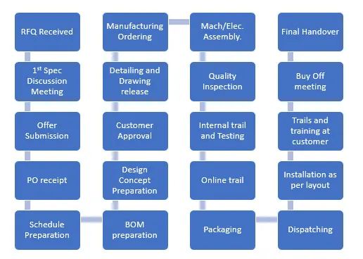
Initially, it starts from the project's basic requirements and specifications in the RFQ stage (Request for Quotation). These stages work by considering the Technical, Timeline, and Financial Factors of the projects and drawing the requirements. Secondly, in the 1ST spec Discussion Meeting, the spec Discussion Meeting, here team conducts an internal meeting considering the above factors and prepares a draft for submission. Thirdly, Offer Submission, after the internal meeting the total number of fixtures used to produce, the Time taken for each stage like Design and Detailing, Simulation, Manufacturing, and Assembly, and the Cost of the whole process. Fourthly, the Customer responds back with PO receipts. Other activities mentioned above in the flow chart are performed. Finally, the Product is handed over to the customer following all the suggestions and requirements.
2. What are the types of joining processes?
Joining processes are used to connect two or more components or parts together to form a complete structure or product. There are various types of joining processes available, each suitable for different materials, applications, and desired joint characteristics. Here are some common types of joining processes:
-
Welding: Welding involves melting the materials to be joined, typically metals, and allowing them to cool and fuse together. It is achieved using various methods such as arc welding, gas welding, TIG welding, MIG welding, and spot welding.
-
Soldering: Soldering is a process used to join metal components by melting a lower melting point metal alloy called solder. The molten solder creates a bond as it solidifies, commonly used in electrical and electronic applications.
-
Brazing: Similar to soldering, brazing uses a filler material with a higher melting point to join metal components. The base metals are heated below their melting point, allowing the molten filler material to flow into the joint by capillary action.
-
Adhesive Bonding: Adhesive bonding involves using adhesives or glues to join components. Adhesives, available in various forms, are applied to the mating surfaces and form a strong bond after curing.
-
Mechanical Fastening: Mechanical fastening methods use mechanical elements like screws, bolts, nuts, rivets, clips, or clamps to join components together. These fasteners create a secure joint through mechanical interlocking or compression.
-
Fastening with Interference Fit: Components can be joined using interference fit, where one component is slightly larger than the other. The press-fit or shrink-fit forces the components together, creating a secure joint without additional fasteners.
-
Fusion Bonding: Fusion bonding, or fusion welding, is used for joining thermoplastic materials. The materials are heated to their melting point, pressed together, and allowed to cool and solidify, resulting in a strong bond.
-
Riveting: Riveting involves using a cylindrical fastener called a rivet to join components. The rivet is inserted into pre-drilled holes, and its ends are formed or pressed to create a permanent joint.
-
Ultrasonic Welding: Ultrasonic welding utilizes high-frequency vibrations to generate heat and bond thermoplastic materials. The materials are pressed together under pressure and subjected to ultrasonic vibrations, which create localized melting and bonding.
-
Friction Stir Welding: Friction stir welding is a solid-state joining process primarily used for metals. It employs a rotating tool that generates frictional heat, softening the material, and mechanically mixing it to form a joint.
These are some of the common joining processes used in manufacturing and construction. The choice of a specific joining method depends on factors such as the materials being joined, joint strength requirements, production speed, cost considerations, and the intended application of the joint.
3. What is Resistance Welding & its application in the automotive sector?
Resistance welding is a joining process that involves the use of electric current and pressure to create a bond between metal components. The process relies on the resistance of the materials to electrical current, generating heat at the joint interface. As the materials heat up, they soften and fuse together, forming a strong weld.
Resistance welding has numerous applications in the automotive sector due to its ability to create high-quality and durable joints. Here are some key applications of resistance welding in the automotive industry:
A. Spot Welding: Spot welding is the most widely used form of resistance welding in the automotive sector. It involves joining two or more metal sheets at discrete points, typically using copper alloy electrodes. Spot welding is used extensively in the assembly of automobile bodies, including joining sheet metal panels, reinforcement members, and brackets.
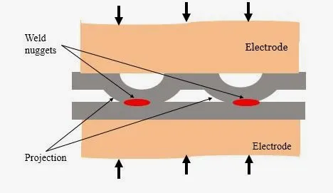
B. Projection Welding: Projection welding is commonly employed in the automotive industry to join components with raised features or projections. It is ideal for joining parts such as brackets, studs, nuts, and electrical terminals. Projection welding provides strong and reliable joints, making it suitable for high-stress applications.
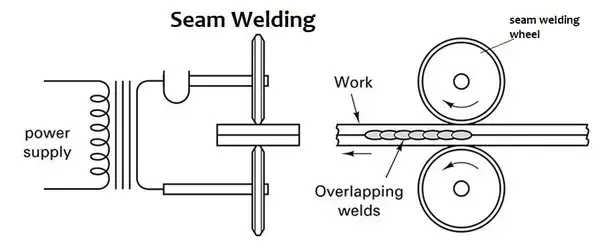
C. Seam Welding: Seam welding is used to create continuous welds along the length of overlapping metal sheets. It is commonly utilized in the fabrication of fuel tanks, exhaust systems, and other automotive components that require leak-tight and durable joints. Seam welding offers high productivity and consistent weld quality.
D. Flash Butt Welding: Flash butt welding is used to join metal components end-to-end. It involves clamping the ends of the components together and passing a high current through them. The resulting heat melts the material, and when the current is interrupted, pressure is applied to forge the weld. Flash butt welding is utilized for joining suspension parts, drive shafts, and other critical automotive components.
E. Resistance Spot Weld Bonding: Resistance spot weld bonding combines spot welding with adhesive bonding. It involves applying adhesive between two metal sheets and then spot welding them together. This hybrid process provides a combination of mechanical strength and corrosion resistance, making it suitable for joining dissimilar materials or lightweight materials like aluminum in automotive manufacturing.
Resistance welding offers several advantages in the automotive sector. It is a fast process, allowing for high production rates. The joints created are strong, reliable, and durable, meeting the rigorous demands of automotive applications. Additionally, resistance welding is cost-effective, energy-efficient, and environmentally friendly compared to some other joining processes.
4. What is fusion welding & types of fusion welding with its application in the automotive sector?
Fusion welding is a type of joining process that involves melting the base materials to be joined and allowing them to solidify, creating a bond between them. The heat required for fusion welding can be generated through various means, such as an electric arc, gas flame, or laser. Fusion welding is commonly used in the automotive sector for joining metal components. Here are some types of fusion welding along with their applications in the automotive industry:
A. Gas Metal Arc Welding (GMAW): Also known as Metal Inert Gas (MIG) welding, GMAW uses a consumable electrode wire and a shielding gas to protect the weld pool from atmospheric contamination. GMAW is widely used in the automotive sector for joining steel components, such as body panels, frames, and exhaust systems.

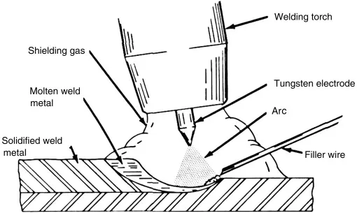
B. Gas Tungsten Arc Welding (GTAW): Commonly known as Tungsten Inert Gas (TIG) welding, GTAW employs a non-consumable tungsten electrode and an inert shielding gas to protect the weld area. GTAW is frequently used in automotive applications for joining aluminum and stainless steel components, including fuel tanks, suspension parts, and engine components.
C. Shielded Metal Arc Welding (SMAW): SMAW, often called stick welding, utilizes a consumable electrode coated with a flux to shield the weld pool. SMAW is employed in the automotive industry for repair work, fabrication of frames, and joining thicker steel components, such as structural parts and chassis components.
D. Flux-Cored Arc Welding (FCAW): FCAW is similar to GMAW, but it employs a tubular electrode filled with flux instead of a solid wire. This flux provides both shielding and additional alloying elements to enhance the weld's properties. FCAW is used in automotive manufacturing for applications such as welding exhaust systems, frames, and structural components.
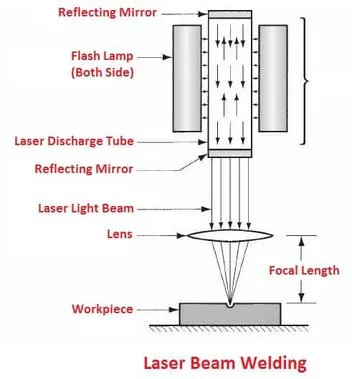
E. Laser Beam Welding (LBW): LBW utilizes a high-energy laser beam to melt and join the materials. It offers precise control and high welding speeds. In the automotive sector, LBW is employed for joining small and intricate components, such as sensors, fuel injectors, and electrical connections.
F. Electron Beam Welding (EBW): EBW uses a focused beam of high-velocity electrons to melt and join the materials. It is capable of producing deep, narrow welds with minimal heat-affected zones. EBW is utilized in the automotive industry for joining critical components, including engine parts, transmission components, and aerospace applications.
Fusion welding techniques provide strong and reliable joints in the automotive sector. The specific welding method used depends on factors such as the materials being joined, the required joint strength, production efficiency, and the intended application of the welded components.
5. What is the 3-2-1 principle?
The 3-2-1 principle, also known as the "locating principle," is a fundamental concept used in the field of manufacturing and machining for accurate and repeatable positioning of workpieces or fixtures. It provides a systematic approach to establish a stable reference for machining operations. Here's an explanation of the 3-2-1 principle without plagiarism:
The 3-2-1 principle consists of three points of contact or constraints that are used to position a workpiece in a desired orientation. These points of contact are achieved through the use of locators or reference features on the workpiece and corresponding surfaces or features on the fixture or machine.
The principle is as follows:
-
Three Points of Contact: The first step involves establishing three points of contact between the workpiece and the fixture or machine. These points should form a stable and non-deformable relationship. Ideally, the three points should be non-collinear, meaning they should not lie on the same straight line. This arrangement prevents rotation and translation of the workpiece in any unwanted directions.
-
Two Planes of Constraint: Once the three points of contact are established, two additional planes of constraint are introduced. These planes are perpendicular to each other and provide further stability to the workpiece. The planes of constraint restrict unwanted movements, such as tilting or twisting, ensuring the workpiece remains securely positioned.
-
One Direction of Insertion: The final step involves defining a single direction of insertion. This direction allows for consistent and repeatable placement of the workpiece in the fixture or machine. It ensures that the workpiece is always positioned in the same orientation, simplifying the setup process and promoting accuracy in machining operations.
By following the 3-2-1 principle, manufacturers can achieve precise and consistent positioning of workpieces, which is crucial for maintaining dimensional accuracy and achieving desired machining results. This principle is widely used in various industries, including automotive, aerospace, and general manufacturing, to ensure efficient and reliable production processes
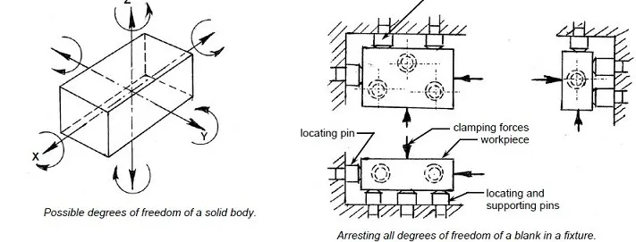
The body coordinate system is a reference frame or coordinate system used to define and describe the position and orientation of an object or body in three-dimensional space. It provides a consistent and standardized framework for spatial measurements and analysis. Here's an explanation of the body coordinate system without plagiarism:
In the body coordinate system, the object or body of interest serves as the reference for defining the coordinate axes. The system is typically defined based on the body's geometric features or functional requirements, making it specific to that particular object or body.
The body coordinate system consists of three mutually perpendicular axes known as X, Y, and Z. These axes are used to describe the position and orientation of the body in three-dimensional space.
-
X-Axis: The X-axis is the horizontal axis that extends from the body, typically from the rear to the front or left to right, depending on the specific application or convention. It represents the body's longitudinal or lateral direction.
-
Y-Axis: The Y-axis is the vertical axis that extends perpendicularly to the X-axis. It represents the body's vertical or height direction.
-
Z-Axis: The Z-axis is the remaining axis that completes the three-dimensional coordinate system. It extends perpendicular to both the X and Y axes, representing the body's transverse or depth direction.
The body coordinate system allows for precise measurements and descriptions of positions, distances, angles, and orientations of points, features, or components on the body. It serves as a common reference frame for various applications, including engineering design, analysis, manufacturing, assembly, and quality control.
It is important to note that different objects or bodies may have different body coordinate systems based on their specific characteristics or applications. Therefore, the body coordinate system is defined and adapted to suit the needs of the particular object or body under consideration.
The body plane system is a reference framework used to define and describe the orientation and motion of an object or body in three-dimensional space. It consists of three mutually perpendicular planes that intersect at a common point, known as the origin. The body plane system provides a standardized way to analyze and communicate the movement and position of body segments. Here's an elaboration of the body plane system and its essentials without plagiarism:
-
Sagittal Plane: The sagittal plane divides the body into left and right halves, creating a vertical plane that passes through the body's midline. It is perpendicular to the frontal plane and extends from front to back. Movements occurring within the sagittal plane include flexion and extension, such as bending forward or backward. The sagittal plane is essential for analyzing movements in activities like walking, running, and bending.
-
Frontal Plane: The frontal plane, also known as the coronal plane, divides the body into front and back halves, creating a vertical plane perpendicular to the sagittal plane. It extends from side to side. Movements occurring within the frontal plane include abduction and adduction, such as raising or lowering the arms sideways. The frontal plane is crucial for understanding movements like side bending, lateral movements, and jumping jacks.
-
Transverse Plane: The transverse plane, also called the horizontal plane, divides the body into upper and lower halves. It is perpendicular to both the sagittal and frontal planes, extending horizontally. Movements occurring within the transverse plane include rotation and twisting motions. Examples include rotating the trunk or hips. The transverse plane is essential for analyzing activities like throwing, swinging, and twisting movements.
These three planes, along with their associated movements, form the foundation of the body plane system. They provide a comprehensive framework for understanding the body's motion and orientation in three-dimensional space.
Essentials of the body plane system:
-
Standardized Terminology: The body plane system uses standardized terminology to describe movements and orientations. Terms such as flexion, extension, abduction, adduction, rotation, and others are used to precisely communicate the direction of movement or position of body segments.
-
Consistent Orientation: The body plane system maintains a consistent orientation, with the sagittal plane positioned in a vertical direction, the frontal plane in a side-to-side direction, and the transverse plane in a horizontal orientation. This consistency allows for clear and unambiguous communication across different disciplines and professions.
-
Common Reference Point: The body plane system utilizes a common origin point where the three planes intersect. This origin serves as a reference point for measuring distances, angles, and positions within the body plane system.
-
Analytical Tool: The body plane system is a valuable analytical tool for assessing movement patterns, identifying joint actions, and understanding the biomechanics of various activities. It aids in diagnosing and rehabilitating injuries, designing exercise programs, and improving performance in sports and physical activities.
By using the body plane system, researchers, clinicians, coaches, and practitioners can analyze and communicate the movement and position of body segments consistently and accurately, leading to better understanding, assessment, and management of human movement.