Week 3:- BiW Fixture Design Methodologies Challenges
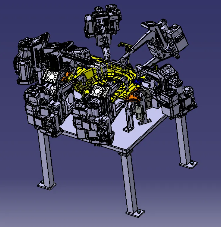
1] What is Design Methodology?
Ans : - Design Methodology is steps followed during the concept designing stages of fixture design.
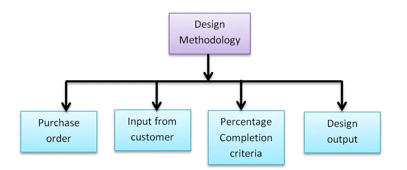
Purchase order: - Order confirmation from customer side or go ahead from customer for detail design on the basis of given concept.
Input from customer: - Major inputs from the customer to study and plan accordingly.
1. Functional requirements: - For which function is the fixture is going to be designed e.g. welding, riveting, gluing, fastening, checking, storage, etc.
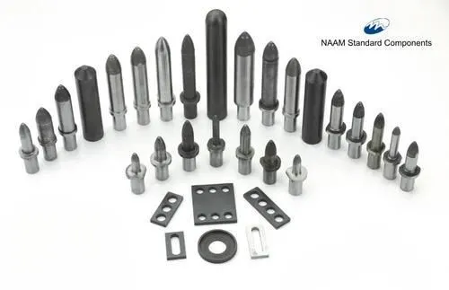
2. Preferred Standard components: - this includes parts which are already available at customer side or standard parts provided from customer. Also by which standards the part should be manufactured standards like ABB, NAAMS, DESTACO, ZYTRAN and TUNKERS. Standard parts like clamps, cylinders, risers, pins, L-blocks, retainers, etc.
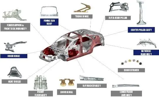
3. Car Products: - a 3D file and 2D drawing of part is given from the customer side to study and analyse tolerances, PLP points, resting points, part list and clamp plan. This helps in planning of the fixture.
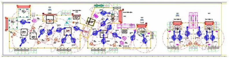
4. Layout: -Layout od entire assembly line to understand the processes, work flow and space constrains for the fixture. Layout provides an information of Flow parts, Station Pitch, Robot Stations, Accessories like Tool changer and tip dresser, Sub assembly links, Platform height, Loading and unloading sequence/heights.
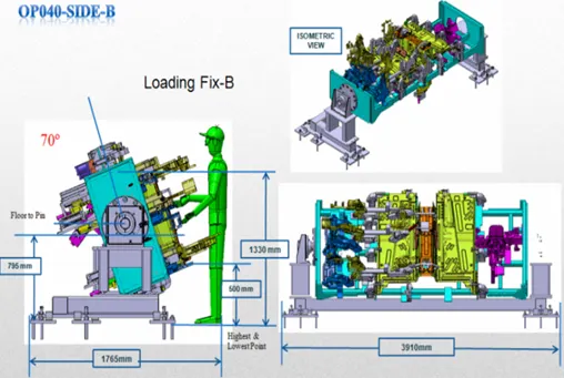
5. Ergo Data: - for Manual fixtures Ergo data is important since it is working with manuals so the fixture should be designed such way that a working person should not suffer any kind of inconvenience while working on the fixture. Ergo data refers to the study of human behavior and movements. Ergo data provides information of loading height, working safety zone of operator, etc.
6. Weld study: - Weld study is given by customer to show where the welding will be conducted accordingly what will be the weld gun position, the locations of weld spots and accordingly the spot weld gun positions. This helps in designing the fixture to leave the space for weld gun.
7. Standard Detailing Templates: -Every company has its own standards for drawing, drawing templates.
Percentage Completion Criteria: - scheduling of Designing processes, time required for completion of designing, simulation, DAP, etc. A predicted timeline is given to the customer. Percentage completion criteria is followed in the design stages and dispatch stages of the welding fixtures
· 0-25% - Input and Concept Design
· 25-40% - Concept approval and Simulation Check.
· 40-85% - Design Freezing and Detailing
· 85-100%- Check and Final dispatch
Design Output: - Provision of design documents such as 2D drawings, 3D step files, Calculations, simulation results, BOM, BOP, etc.
* Unitized tools: - (multiple units on a common base) require two types of drawing sheets
Key sheet- An index of units and their placements on the tool base
Layout sheet- A detail drawing of individual unitsto include all of their components
* Non-unitized tools:- Tools that can stand alone and can be detailed completely on a layout sheet
-*-*-*-*-*-*-*-*-*-*-*-*-*-*-*-*-*-*-*-*-*-*-*-*-*-*-*-*-*-*-*-*-*-*-*-*-*-*-*-*-*-*-*-*-*-*-*-*-*-*-
2] What are the inputs required from the customer to start designing a Fixture?
ANS :- Major inputs from the customer to study and plan accordingly.
1. Functional requirements: - For which function is the fixture is going to be designed e.g. welding, riveting, gluing, fastening, checking, storage, etc.
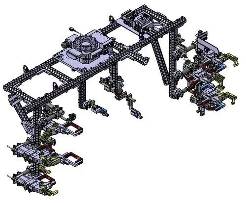
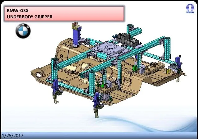
2. Preferred Standard components: - this includes parts which are already available at customer side or standard parts provided from customer. Also by which standards the part should be manufactured standards like ABB, NAAMS, DESTACO, ZYTRAN and TUNKERS. Standard parts like clamps, cylinders, risers, pins, L-blocks, retainers, etc. 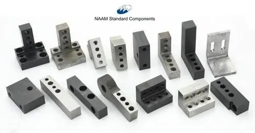
3. Car Products: - a 3D file and 2D drawing of part is given from the customer side to study and analyse tolerances, PLP points, resting points, part list and clamp plan. This helps in planning of the fixture.
4. Layout: -Layout od entire assembly line to understand the processes, work flow and space constrains for the fixture. Layout provides an information of Flow parts, Station Pitch, Robot Stations, Accessories like Tool changer and tip dresser, Sub assembly links, Platform height, Loading and unloading sequence/heights.
5. Ergo Data: - for Manual fixtures Ergo data is important since it is working with manuals so the fixture should be designed such way that a working person should not suffer any kind of inconvenience while working on the fixture. Ergo data refers to the study of human behavior and movements. Ergo data provides information of loading height, working safety zone of operator, etc.
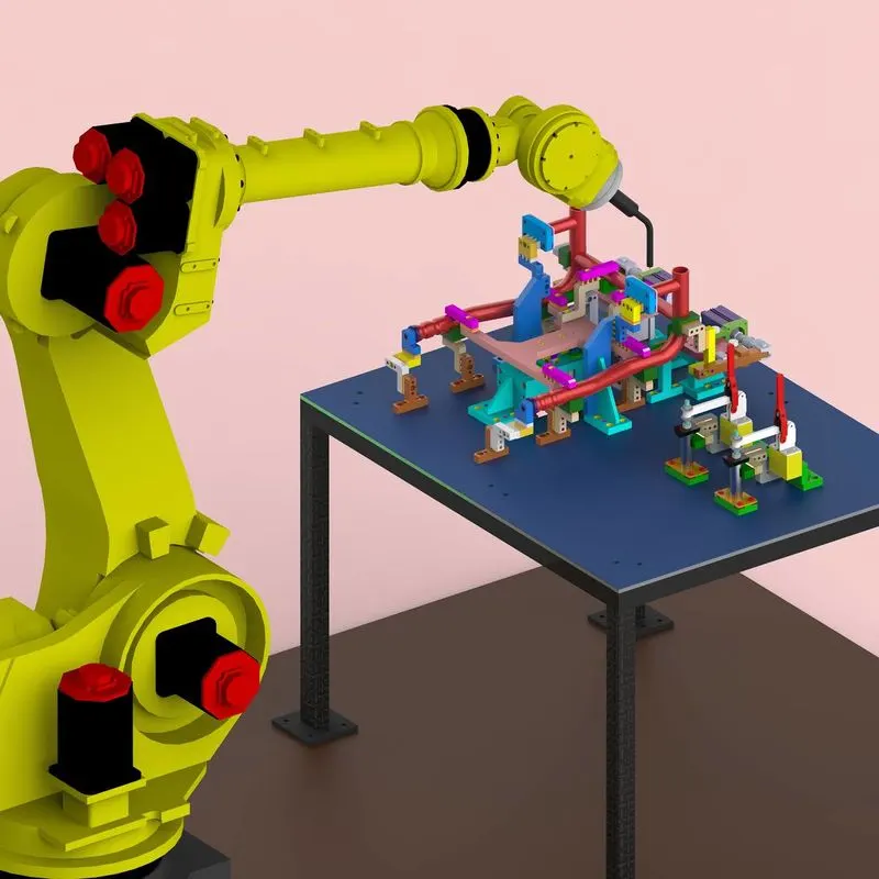
6. Weld study: - Weld study is given by customer to show where the welding will be conducted accordingly what will be the weld gun position, the locations of weld spots and accordingly the spot weld gun positions. This helps in designing the fixture to leave the space for weld gun.
7. Standard Detailing Templates: -Every company has its own standards for drawing, drawing templates.
-*-*-*-*-*-*-*-*---*-*-*-*-*-*-*-*-*-*-*-*-*-*-*-*-*-*-*-*-*-*-*-*-*-*-*-*-*-*-*-*-*-*-*-*-*-*-*-*-*-*-*-*-*-*-*-*-*-*-*-*-*-*-*-*-*-*-*-*-*-*-*-*-*-*-*-*-*-*-*-*-*-*-*-*-*-*-*
3] What is the input we get from "Car Products"?
Ans: - To design a fixture for any customer, it is required to generate information from given data from customer called car product. The car product helps in building the fixture and designing of the fixture.
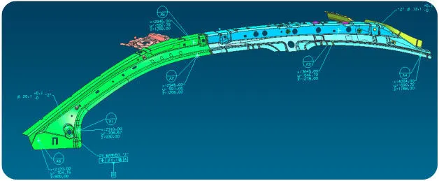
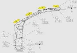
1. GD & T: - Geometric dimensioning and tolerance of a product provides the information of PLP pin size and its tolerance. The location of resting Mylayers and there tolerance. Clamp positions, their locations, dumps and slide information of each station. Sequence of opening of clamps and dumps.
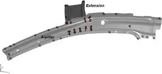
2. Part list: - Part list of a car product provides information about the assembly going to welded. What kind of assembly is going to be welded?, it’s child parts, Where they are located in the assembly, their sequence of alignment, Part thickness, part number, part revision, part wt.
3. Clamp plan: - It is an information which is decided after studying the part and it’s assembly. The clamp plan is made in such a way that part could be easily placed and removed from fixture. From this information the location of clamping units, PLP ping location, clamping sequence is decided. The resting mylare location and dump location is also decided from the same.
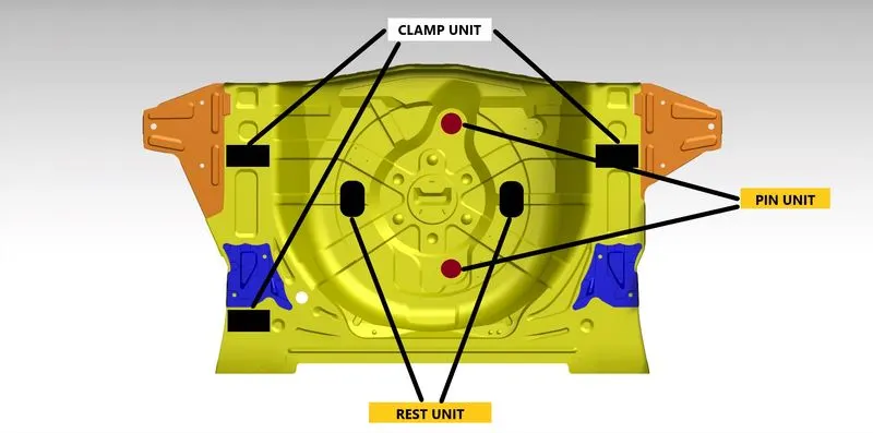
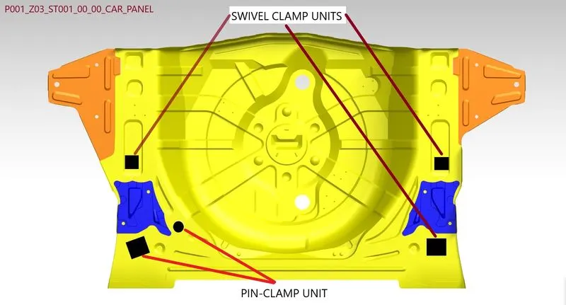
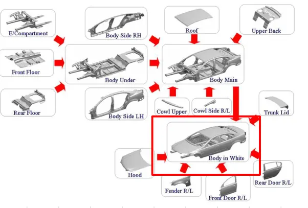
4. Product assembly process sheet: - This sheet is given from the customer to know the actual sequence of assembly of car product in car body. This gives the information about the plan of product assembly in car body where and when it will be assembled in a car body. Its sequence of assembling.
4] What is the Clamp plan?
Ans:-
It is an information which is decided after studying the part and it’s assembly. The clamp plan is made in such a way that part could be easily placed and removed from fixture. From this information the location of clamping units, PLP ping location, clamping sequence is decided. The resting mylare location and dump
5] What is the purpose of a Layout?
Ans: - Layout of entire assembly line to understand the processes, work flow and space constrains for the fixture. Layout provides an information of Flow parts, Station Pitch, Robot Stations, Accessories like Tool changer and tip dresser, Sub assembly links, Platform height, Loading and unloading sequence/heights.
6] What is Ergo data?
Ans; - for Manual fixtures Ergo data is important since it is working with manuals so the fixture should be designed such way that a working person should not suffer any kind of inconvenience while working on the fixture. Ergo data refers to the study of human behavior and movements. Ergo data provides information of loading height, working safety zone of operator, etc.
7] What do you understand by Weld study?
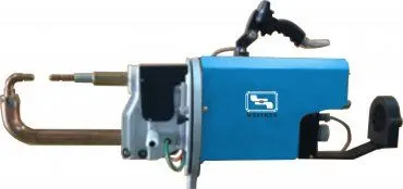
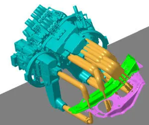
Ans: - Weld study is study of weld gun ergonomics, this study shows weld gun positions and locations in the fixture. This information gives the information about the clashes of weld gun with the risers and clamps and PLP pin while doing the welding processes. This activity should be done while designing the welding fixture.
A weld study includes,
1. Weld gun details.
2. Weld matrix and weld points
Weld points includes
A) Geo welding points: - these are primary welding points which are done while joining primary parts.
B) Re-spot weld points: - These are secondary welding points which are done after joining the primary parts i.e. Geo spotting. This is done while joining the secondary and primary parts.
8] What are the criteria for percentage completion in the designing stage? Explain it in detail
Ans: - scheduling of Designing processes, time required for completion of designing, simulation, DAP, etc. A predicted timeline is given to the customer.
Percentage completion criteria is followed in the design stages and dispatch stages of the welding fixtures
· 0-25% - Input and Concept Design
· 25-40% - Concept approval and Simulation Check.
· 40-85% - Design Freezing and Detailing
· 85-100%- Check and Final dispatch
9] Brief about "Output" in design?
Ans: - Provision of design documents such as 2D drawings, 3D step files, Calculations, simulation results, BOM, BOP, etc.
* Unitized tools: - (multiple units on a common base) require two types of drawing sheets
Key sheet- An index of units and their placements on the tool base
Layout sheet- A detail drawing of individual units to include all of their components
* Non-unitized tools:- Tools that can stand alone and can be detailed completely on a layout sheet
The design output should compile following points
· Approved standard components are to be used wherever possible.
· Design must be as simple and economical as possible.
· Design must comply with all current safety and ergonomic requirements.
· Design must provide controlled and damage free handling of product.
· Adequate error proofing provision must be incorporated into each design by providing Proximity switches, rough locators etc.
· The weight of moving parts must be kept to a minimum while maintaining maximum strength.
· Frames and structures are to be simple and sturdy.
· Design clearance and accessibility for routine maintenance and service.
· Motion control must be considered on any moving equipment’s.
· Designer is responsible to validate clamps and all weld guns.
10] What do you understand by structuring a design tree? How does it reduce errors during the design process?
Ans: - structuring a design tree implies to a process where all the assemblies and parts are named in a specific standard. Different customers have different set of standards to structure a design tree.
· It is an important process which helps us to identify a specific part or assembly, as to which project, tool or unit, it belongs to.
· This helps us to avoid the errors during design study, manufacturing, assembly, inspection, etc.
· If the parts or assemblies are not named properly or the design tree is not structured properly, it will create confusion to understand the design and, may create major possibilities of making an error.
· Naming of a fixture or a unit or a part, gives the information as to which project or zone or assembly do they belong.
· It can help us to identify the quantity of items of same type or different types that are being used in an assembly.
11] What are units? Mansion 5 types of units.
Ans: - Units are individual subassemblies which support the BIW panel and locate the panel. There are different types of units used in a BIW fixture for locating the component, fixation, resting, etc.
Types of units in a BIW fixture: -
· Rest unit
· Fixed pin unit
· Retract pin unit
· Rough locator unit
· Sensor unit
· Base unit
· Slide unit
· Dump unit
12] Describe Fixed Pin units & their purpose?
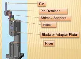
Ans: - Fixed pin unit is unit designed to locate the car panel using pins. A fixed pin unit should have at least two schemes in two directions. It has following parts.
1) Pin
2) Pin retainer
3) Shims/ spacers
4) Block
5) Blade/ adaptor plate
6) Riser.
13] What are the different parts of a fixed unit?
Ans:- In a fixed pin unit there are different types of components.
1) Pin: - Pin is a primary locating component where it guides in a PLP point which is a hole of a desire diameter. This restricts the X and Y direction of a component. A pin should be made with same dimension as the PLP hole but should have clearance tolerance with the hole.
2) Pin retainer: - Pin retainer is part which holds the pin in place by fixing in it.
3) Shims: - shim is a thin and often tapered or wedged piece of material used to overcome the stack up tolerance of a BIW part. It also used to adjust the pin location in X and Y direction.
4) Riser: - riser is a structure to mount the toggle clamp, rest mylare or a locating pin.
14] What is the purpose of making a Rest unit & describe its parts?
Ans: - A rest unit is designed to rest or support the BIW part using a NC block/ mylare.
Following are the different parts of the rest unit.
· Simple unit has a riser and a rest mylare or NC block with a shim between them to adjust in z direction.
· You can just manufacture restaurant there and you can use the same blade and razor.
NC blocks: -
NC blocks are versatile blocks that can be machined any desirable fixture component. Because they come as a blank block, the possibilities are endless adding new tap holes or grinding down to your specifications are quick and simple.
Shim: - shim is a thin and often tapered or wedged piece of material used to overcome the stack up tolerance of a BIW part. It also used to adjust the rest mylar in Z direction.
Riser: - riser is a structure to mount the toggle clamp, rest mylare or a locating pin.
15] What are the basic fundamentals to design a Sensor unit?
Ans: - sensor unit is a unit designed to sense the BIW part by using electrical sensors the signal is fade to PLC which is our programmable logic control unit and the assigned process will happen.
Fundamentals of sensor unit design
Every single loose panel which are being welded in a tool should be sensed.
For every panel at least sensor should be assigned to sense it. The quantity of sensors could be increased as the size of BIW part increases. For larger part there should be two or three sensors assigned to sense the part.
Types of sensors:
1) Proximity sensor: - proximity sensor are used to sense the part within the range of 5- 10 mm. these sensors used to detect the smaller and individual parts.
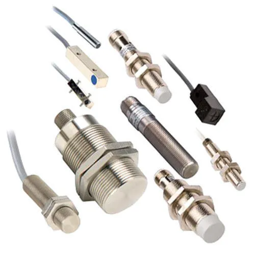
2) Laser sensor:- a laser sensor used where no nearby mounting is available to mount a proximity sensor. This sensor ranges over 500 mm.
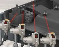
3) Photo electric sensor: - a photo electric sensor uses light emitter and a receiver. This sensor used to detect any human interaction with the fixture so that the process should not start while human interaction and avoid any kind of accident.