Week 2:- BiW Fixture Basics Challenge
1] What is the process of project execution activity?
ANS:- The process of project execution activity is activity where planing of project execution done from quotation request to final project delivery, scheduling of all work activities and managing project work execution. in process of project execution activity following processes involved.
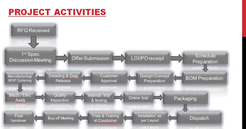
1. RFQ(Request For Quotation):- RFQ is very important process in a project execution since it starts the project activities. RFQ is process where costumer gives technical data, requirements of project, specifications, etc. in form of data, documents to study and to work on it. From this data the project timeline and process decided, also the technical and commercial offer made for the customer and submit to the customer.
2. Offer submission:- based on RFQ a technical and commercial offer is made to costumer. After receiving the RFQ the internal project management team reviews the requirements and project needs and gives the project timeline and schedule the project activities. The total duration for completion of project depends on time require for design team, time require for manufacturing team, time required for assembling, time required for dispatch and installation and time required for commissioning the project at costumer’s end. The bought out parts to be decided. By compiling these inputs for internal project management team gives the timeline and the project execution activities need to execute the projects. Based on these inputs a technical and commercial offer is made to the customer.
3. LOI/PO receipt:- Customer reviews the offer made to him and considers the factors like cost of project, time duration to execute the project, whether the project timeline sinks in with its project goal and the cost escalation, whether the requirements fulfilled for the project. If the offer sites between these parameters the customer will raise a LOI/PO for the project which will closes the deal between customer and the wander.
4. Schedule Preparation:- After receiving the LOI/PO the actual project work starts to make project happen project management team release a Schedule through which the project will be proceed. In this schedule the time duration required for each work is recorded and scheduled work for each team. By this schedule the Design team, Production team, Simulation team, Assembling and manufacturing team will work and complete their tasks within this time duration.
5. BOM Preparation:- In RFQ costumer has mentioned project requirements, based on these requirements a BOM is prepared where bought out parts and in-house parts are mentioned for the fixture. Bought out parts such as motor, gear box, bolts, clamps, pneumatic cylinders, etc,. In-house manufactured parts such as base table, risers, Mylers, bushes, PLP pins, etc,. With this BOM the commercial offer is made to customer.
6. Design Concept Preparation:- Based on BOM a 3D concept of the project is prepared for customer approval. With this concept design the project will proceed to its final stage.
7. Customer approval :- The Prepared Design concept is showed to the customer for confirming the design path and design inputs from customer. This process is called DAP( Design Approval Process ).
8. Detailing and Drawing Release:- After DAP the customer inputs incorporated in 3D design and fixture gets its final shape. This is the finalising the design and Releasing the drawings for the production and manufacturing.
9. Manufacturing/ BOP Ordering:- Manufacturing of fixture starts after the release of fixture drawings and bought out parts are ordered for the assembly so that the bought outs will arrive at the time of assembly of fixture. The quality inspections of manufactured individual parts are carried out for the final assembling.
10. Mechanical and electrical assembling:- After manufacturing of parts the mechanical and electrical assembly is carried out for final assembly of the fixture. The electrical assembly is done for the PCB and PLC by electrical persons. The mechanical assembly is done by mechanical persons.
11. Quality inspection:- After mechanical and electrical manufacturing and final assembling the quality of fixture checked by CMM( Coordinate Measuring Machine ), whether the all parts are fitted well placed in assembly. If any part is not fitted well in assembly at it's place then it is adjusted by putting scheme under the part or removing the scheme.
12. Internal trial & Testing:- To check whether the fixture working well the internal trials are carried out. The assembly to be welded is sets properly within the fixture assembly. The PLP pins are well inserted in the final part assembly. In this all working actuators and clamps are checked. Welding gun approachability is feasible or not. The welded final part is checked for quality testing. The final adjustments made to meet the customer requirements.
13. Online trial:- The fixture is now ready for full scale trial. The fixture is run on its final full scale production volume to prove the design to customer. all electrical connections are working well.
14. Packaging:- After customer approval the fixture is ready to be delivered to the customer. The packaging is the most important part of the process since while delivering the fixtures the customer will get a defect less fixture and it should not damage while delivering the fixture.
15. Dispatch:- At customers end the dispatch of fixture should be carried out seamlessly and in presence of authorising personals. Also the documentation should be cleared to the customer. Take the approval from the customer and then place the fixture at its place.
16. Installation as per layout:- Dispatch at customer end the fixture should be installed as per the factory layout. All electrical connections should be well connected.
17. Trials and training at customer end:- There will be production trials to meeting the quality bench marks. The committed quantity of the parts while making the deal is achieved or not. Then training for the operators, staff members and engineers to understand how the fixture is working, sequence of working.
18. Buy Off Meeting:- If there are other things that need to be incorporated in the fixture, anything else needs tobe added in the fixture or something missing in the fixture which is prescribed in the LOI/PO. These things should be taken care of.
19. Final Handover:- After satisfying all the customer requirements the project will be handed over to the customer.
-*-*-*-*-*-*-*-*-*-*-*-*-*-*-*-*-*-*-*-*-*-*-*-*-*-*-*-*-*-*-*-*-*-*-*-*-*-*-*-*-*-*-*-*-*-*-*-*-*-*-
2] What are the types of joining processes?
ANS:-
There are different joining processes in BIW parts. There are some traditional welding processes resistance welding, arc welding and fusion welding used for steel for assembly of panels into the body structure. Brazing and soldering techniques also used in now days for metal joining processes. Adhesives and mechanical fastening often used in light weight designs.
The durability and performance of any structure is largely dependent on the quality and the design of the component joints. The BIW car body structure cannot made in a single piece, it is divided in small structural pieces by joining them with different joining methods a complete car body is manufactured.
There are 2 fundamental options for joining materials and component
- Mechanical joining
- Metalurgical joining
- Resistance welding:- resistance welding is a thecnology widely used in manufacturing industry for joining metal sheets and components. The weld is made by conducting high voltage current through the metals at localized points the pressure is applied by two electrodes over the joing parts and a localize resistance is created, the haet generated deuto the resistance melts the joining prats localy. A force is always applied before, during and after the application of current to confine the contact area at the weld interfaces and in some applications to forge the work piece.
Types of resisrance welding
* Resistance spot welding
* Resistance seam welding
* Resistance spot welding
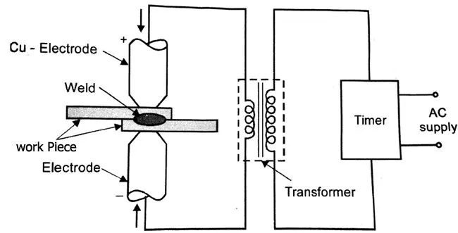
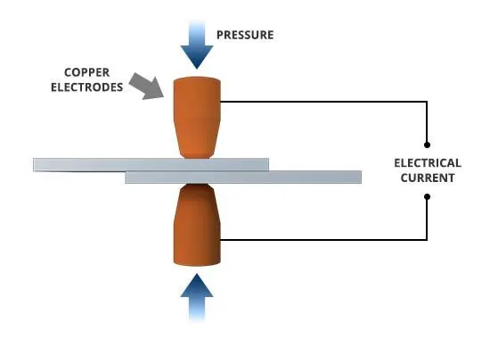
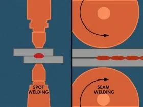
2. Resistance spot welding:- Spot welding (also known as resistance spot welding) is a resistance welding process. This welding process is used primarily for welding two or more metal sheets together by applying pressure and heat from an electric current to the weld area.
It works by contacting copper alloy electrodes to the sheet surfaces, whereby pressure and electric current are applied and heat is generated by the passage of current through resistive materials such as low carbon steels
The process involves applying pressure and heat to the weld area using shaped alloy copper electrodes which convey an electrical current through the weld pieces. The material melts, fusing the parts together at which point the current is turned off, pressure from the electrodes is maintained and the molten “nugget” solidifies to form the joint.
Advantages:-
* Short weld time and hence high volume production possible.
* Highly adaptable to automation and robotic techniques.
* Does not affects on part asthetics.
* Does not require any filler material.
* Strength and durability of automobiles largely depends on quality od RSW.
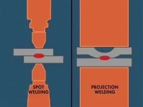
3. Projection Welding:- Projection welding is a resistance weld where the design or shape of the part is used to make discreet individual point contacts to concentrate the current during the welding process. In most applications multiple small projections are formed on one surface of the parts to be welded. These projections can be round dimples, elongated ridges, circular, or the extended corners of weld nuts. Two round wires placed together at 90 degrees form a point contact. This would also be a projection weld. When the mating parts are brought together these projections concentrate the current flow and generate the heat in these locations. When the projections get hot they collapse as the weld nugget forms. After cooling the result is several weld nuggets holding the part together. Of course in the case of cross wire welding there is one weld per crossing location but normally many are welded at the same time as in fencing.
The circular ring projection on the bottom of a hydraulic fitting could make a tight hydraulic seal. The cross wire weld could be fencing or rebar in a roadway. The weld nut holds the various parts bolted on your automobile.
The process is the same as a spot weld but in this case the electrode is not used to concentrate the heat. The part projection or arrangement does this. Multiple welds can be made at the same time when multiple projections are present. It is a very efficient process and not as electrode dependent as spot welding. Other factors must be controlled such as alignment, projection consistency, welder follow up and with nut welding thread protection. Projection welds and processes are designed and developed to fit the various applications.
Applications:-
* Used for mechanical fixing of auto body structures eg, Weld nuts
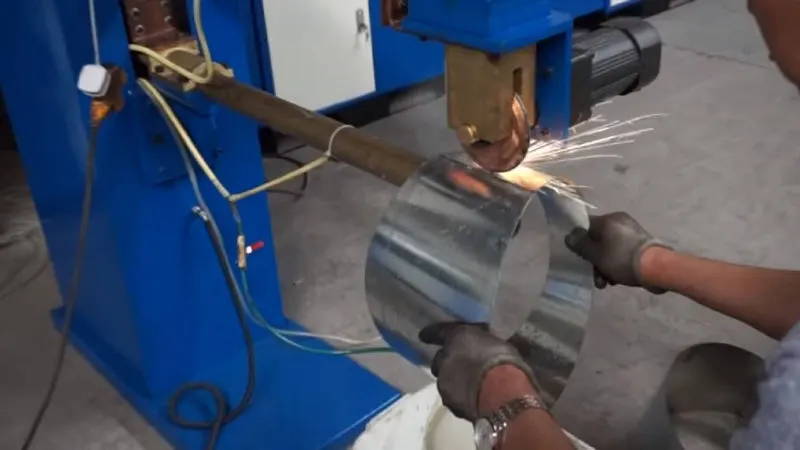
4. Seam Welding:- Seam welding is very similar to spot welding. There is still an electrode but it is two opposing wheels rather than two pointed electrodes. Force and current is applied through the wheel just as in spot welding. The control timing and wheel speed determine the spacing of the spots. They can be made to overlap and be fluid tight or separated. If separated this is called a roll spot weld. Fluid tight applications could be dishwashers, washing machines, tin cans and metal drums.
It is a leak tight welding process. It is used where no leakage is reuired and in leakage free assemblies. such as fluide tanks .
Application :-
Seam welding is mostly applied in manufacturing of containers, radiators, and heat exchangers.
4. Arc welding:-
The process consists of two sub processes either consumable electrode or non-consumable electrode.
An arc produced between tip of the electrode and work piece tobe welded, by use of an AC or a DC power supply.
Types of arc welding:-
* Manual metal arc welding.
* Ges-shielded tungstant arc welding ( Tungstanten Inert Gas welding ).
* Gas-shielded metal arc welding ( Metal Inert Gas welding ).
* Plasma arc welding.
5. Manual Metal Arc Welding:-
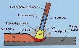
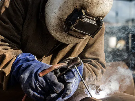
Manual metal arc welding ( MMA or MMAW ) also known as Shielded metal arc welding ( SMAW ), or informaly as stick welding. It involves striking an arc between a covered metal electrode and a workpiece. The heat of the arc melts the parent metal and the electrode which mix together to form, on cooling, a continuous solid mass. The central metal electrode or core wire acts as a consumable, providing the filler metal for the weld. The metal electrode is covered with flux which sprades over the exposed moltan metal to prevent the moltan metal from oxidation.
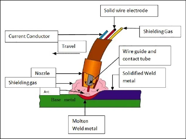
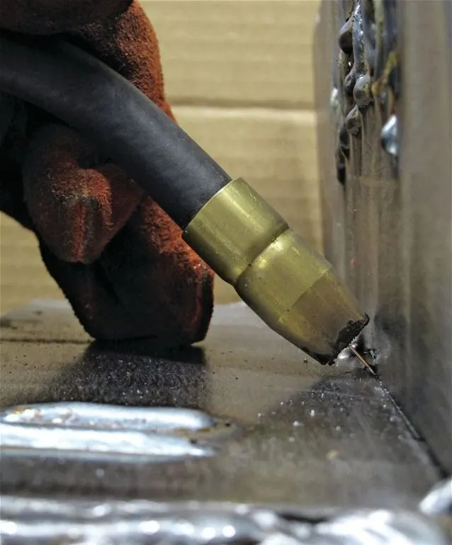
6. Gas-shielded metal arc welding ( Metal Inert Gas (MIG) welding):-
Metal Inert Gas (MIG) and Metal Active Gas (MAG) welding are gas metal arc welding (GMAW) processes that use heat created from a DC electric arc between a consumable metal electrode and a work piece which melt together to create a weld pool that fuses to form a join. An inert gas is used to seperate the exposed moltan metal and atmosperic air so that the joint prevented from oxidation.
MIG/MAG is similar to MMA in that heat for welding is produced by forming an arc between a consumable metal electrode and the work piece; the electrode melts to form the weld bead. The main difference is that the metal electrode is a small diameter wire fed through the contact tip from a wire feeding spool gun, while a shielding gas is fed through the welding torch. As the wire is continuously fed, the manual process is sometimes referred to as semi-automatic welding. MIG and MAG welding both use gas bottles to provide the shielding gas and compatible filler materials. For example, to weld aluminium, an aluminium wire should be used, whereas steel MIG welding would require an appropriate steel filler wire.
following parts are used in MIG welding
* Consumable Electrode
* Inert Gas Supply
* Welding head
* A.C. or D.C. Power supply
7. Gas-shielded tungsten arc welding ( Tungsten Inert Gas (TIG) welding):-
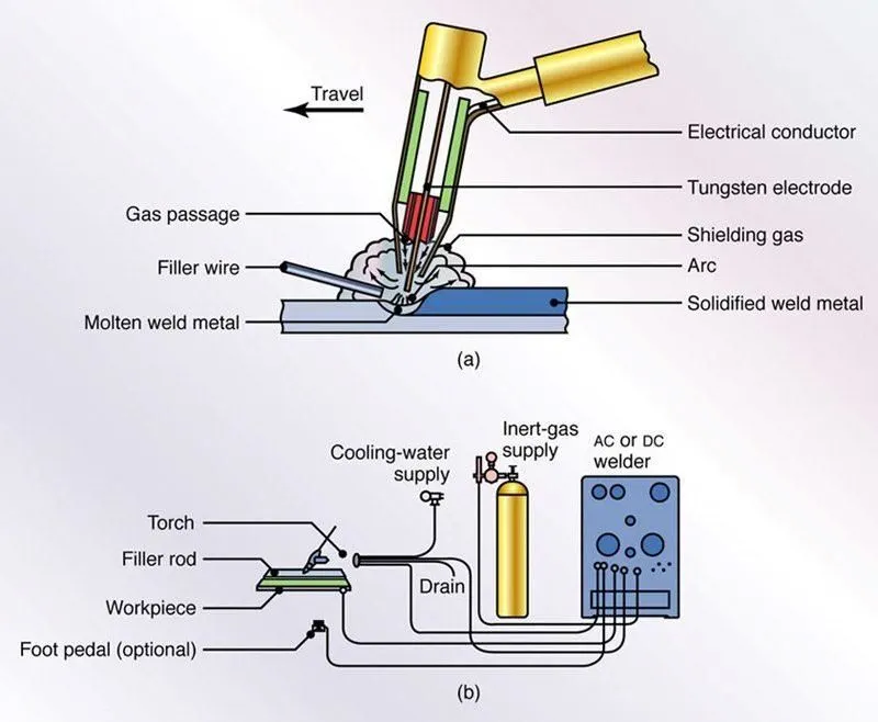
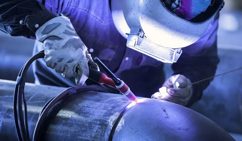
Tungsten inert gas (TIG) welding is an arc welding that uses a non-consumable tungsten electrode to weld two or more work pieces. It is very much similar to Metal Inert Gas ( MIG ) welding
Tungsten Inert Gas (TIG) welding uses the heat generated by an electric arc struck between a non-consumable tungsten electrode and the work piece to fuse metal in the joint area and produce a molten weld pool. The arc area is shrouded in an inert or reducing gas shield to protect the weld pool and the non-consumable electrode. The process may be operated autogenously, that is, without filler, or filler may be added by feeding a consumable wire or rod into the established weld pool. TIG produces very high quality welds across a wide range of materials.
Following components are necessary to prefore Tungstan Inert Gas Welding:
* Power Supply
* Non-consumable tungsten electrode
* Inert Gas Supply.
* Filler rod (depend on the nature of work piece)
* Welding Head.
8. Mechanical fastning:-
The joining of material combinations which cannot be easily welded such as pre painted steels or very dissinilar metals. Eg. Al application in auto body make use of mechanical fatening techniques to overcome the poor inherent weld ability of Al.
The joining of materials in applications where high fatigue life is critical compared to static strength. The joining of materials where a long tool life is of relative importance.
screws ans bolts
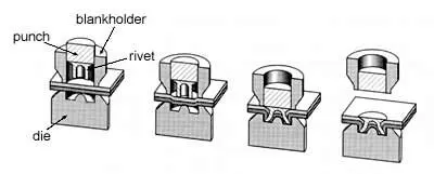
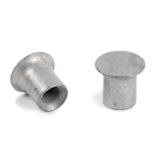
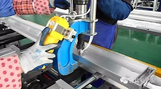
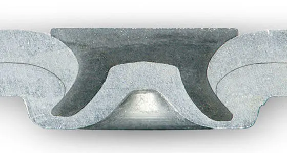
9. Self piercing riveting:- Self-piercing riveting is a high-speed mechanical fastening process for point joining sheet material, typically steels and aluminium alloys. It is a single step technique, generally using a semi-tubular rivet to clinch the sheets in a mechanical joint, there is also a process variant which utilises soil revets.
As the name suggests, pre-drilled holes are not required, allowing the joint to be made rapidly in one operation. The process cycle is shown in cross-section below.
8. Hemming :-
Hemming and seaming are two simmiler working processes in which a sheet metal edge is rolled over onto itself. Hemming is process in which the edge is rolled flush to itself, while a seam joins the edges of two materials.
9. Adhesive Bonding:-
Adhesive bonding is used to farsten two surfaces togehter, usually producing a smooth bond. This joining technique involves glues, epoxies or various plastic agents that bond by evaporation of a solvent or by curring a bonding agent with heat pressure or time.
-*-*-*-*-*-*-*-*-*-*-*-*-*-*-*-*-*-*-*-*-*-*-*-*-*-*-*-*-*-*-*-*-*-*-*-*-*-*-*-*-*-*-*-*-*-*-*-*-*-*-
3] What is Resistance Welding & its application in the automotive sector?
ANS:- resistance welding is a technology widely used in manufacturing industry for joining metal sheets and components. The weld is made by conducting high voltage current through the metals at localized points the pressure is applied by two electrodes over the joining parts and a localize resistance is created, the heat generated due to the resistance melts the joining parts locally. A force is always applied before, during and after the application of current to confine the contact area at the weld interfaces and in some applications to forge the work piece.
Cost-effective joining technology that continues to be very popular in the automotive industry where high reproducibility and automation are essential criteria. An additional advantage is that, with a suitable choice of parameters, a high quality of joints can be obtained without being dependent on a welder’s ability.
Resistance Spot Welding is a pressure welding process. The sheets are pressed together locally with the help of fitted copper electrode welding guns that then have a current applied to them. As a result, Joule heating locally melts the joining partners at the junction resulting in a cohesive composite once the joint has solidified.
Applications of Resistance welding in automotive industry
1. Resistance spot welding :- spot welding has wide range of use in automotive sectore such as metal joining processes car body panels join together by spot welding processes.
2. Projection welding process:- in projection welding processe bolts, sheet metal parts with projections on them, nuts on sheet metal joined by this process.
3. Seam welding:- seam welding processes i used for leake proofing. It applies where leakege is not tolerated. For canning, tanks,radiators etc.
-*-*-*-*-*-*-*-*-*-*-*-*-*-*-*-*-*-*-*-*-*-*-*-*-*-*-*-*-*-*-*-*-*-*-*-*-*-*-*-*-*-*-*-*-*-*-*-*-*-*-
4. What is fusion welding & types of fusion welding with its application in the automotive sector?
ANS:- Fusion welding is a process that uses heat to join or fuse two or more materials by heating them to melting point. The process may or may not require the use a filler material. External application of pressure is not required for fusion welding processes, except for resistance welding, where substantial contact pressure is required during welding for sound joining.
Fusion Welding Processes
Fusion welding processes can be grouped according to the source of the heat, for example, electric arc, gas, electrical resistance and high energy.
These processes include:
Arc Welding Processes - with the most common processes being:
Shielded Metal Arc Welding (SMAW), also known as manual metal arc welding (MMA or MMAW), flux shielded arc welding or stick welding. Suitable for welding ferrous and non-ferrous materials in all positions.
Metal Inert Gas Welding (MIG) and Metal Active Gas Welding (MAG), also known as Gas Metal Arc Welding (GMAW). MIG and MAG welding are the most common arc welding processes, in which an electric arc forms between a consumable wire electrode and the workpiece leading them to melt and join. Both use a shielding gas to protect the weld from airborne contaminants, or oxidation in the case of MIG welding.
Tungsten Inert Gas Welding (TIG), also known as Gas Tungsten Arc Welding (GTAW). This arc process uses a non-consumable tungsten electrode to create the arc between the electrode and the base plate. An inert shielding gas is used to protect from oxidation or other atmospheric contamination. This process can be used autogenously on thin parts, but will require the addition of a wire, rod, or consumable to be added for thicker parts.
Plasma Arc Welding (PAW). This process uses an electric arc created between an electrode and the torch nozzle. The electric arc ionises the gas (usually argon) in the chamber creating what is called a 'plasma.' It is then forced through a fine bore copper nozzle that constricts the arc and directs it to the workpiece, allowing the plasma arc to be separated from the shielding gas (which is usually made from a mixture of argon and hydrogen).
Submerged Arc Welding (SAW). This frequently-used arc welding process uses a continuously-fed consumable electrode and a blanket of fusible flux which becomes conductive when molten and provides a current path between the workpiece and the electrode. The flux also prevents spatter and sparks while suppressing ultraviolet radiation and fumes.
Flux Cored Arc Welding (FCAW). Developed as an alternative to SMAW, this process uses a continuously fed consumable electrode with a flux and a constant voltage or constant current power supply. Sometimes using a shielding gas this process can also just use the flux to provide protection from the atmosphere.
-*-*-*-*-*-*-*-*-*-*-*-*-*-*-*-*-*-*-*-*-*-*-*-*-*-*-*-*-*-*-*-*-*-*-*-*-*-*-*-*-*-*-*-*-*-*-*-*-*-*-*-*-*-*-*-*-*-*-*-*-
5] What is the 3-2-1 principle?
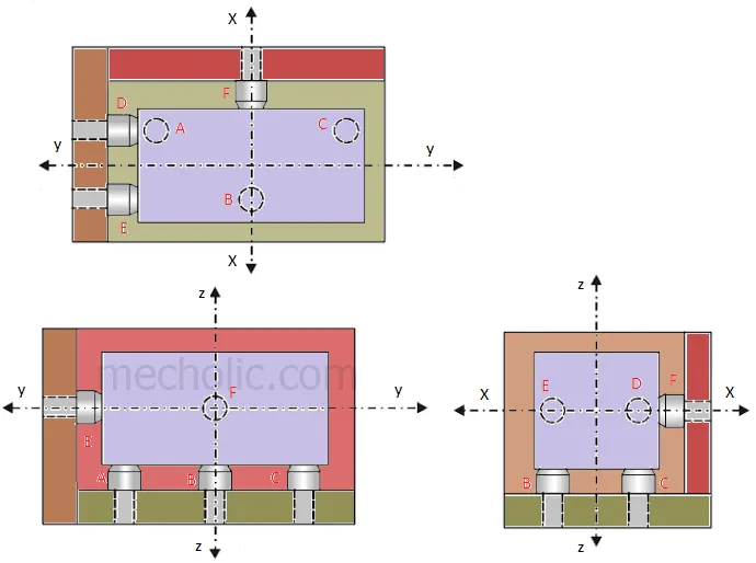
ANS:- Every fixture is designed by using 3-2-1 principle. This principle states that work piece should be positioned in a machine by restricting its all degrees of freedom.
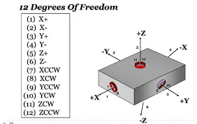
Degrees of freedom:- there are 12 degrees of freedom in X, Y and Z direction to move an object, that are 6 linear and 6 rotational.
1)+ve and -ve X direction
2)+ve and -ve Y direction
3)+ve and -ve Z direction
4)Clock wise and counter clock wise X axis
5)Clock wise and counter clock wise Y axis
6)Clock wise and counter clock wise Z axis
3-2-1 principle is applied by following steps-
Step 1:- By placing 3 points at the bottom of the work piece will restrict rotational movement along X and Y axis.
Step 2:- By placing 2 points at the one of the side of work piece will restrict linear movement along X or Y axis and rotational movement along Z axis.
Step 3:- By placing 1 point at front or back of the work piece will restrict linear movement along X or Y axis.
Step 4:- Remaining linear movements along X, Y and Z axis will be restricted by using clamping.
-*-*-*-*-*-*-*-*-*-*-*-*-*-*-*-*-*-*-*-*-*-*-*-*-*-*-*-*-*-*-*-*-*-*-*-*-*-*-*-*-*-*-*-*-*-*-*-*-*-*-