Week 3:- BiW Fixture Design Methodologies Challenges
Week 3:- BiW Fixture Design Methodologies Challenges
1) What is Design Methodology?
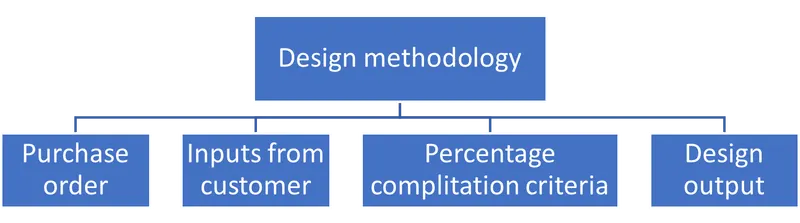
Purchase order :- Purshace order is a necessary documet for confirmation to start desigh or a project it involves payment details, terms and condiation, technical and non technical commorcial information and along with timelines.
Inputs from customers :- To start a fixture design we have to get some inputs from customer like technical requirements, Desihn data and all other information to proced for the design of a BIW fixture.
Percentage complitation criteria :- This is a set of information or a schedule about when we are proceding to start the project, when er are resourcing the material and all, time required for project complition and it includes all timelines.
Design outputs :- The design ootputs are nothing but Documantations of Design data like 2D and 3D drafts and detailed drawungs which we have to submit to customer.
2) What are the inputs required from the customer to start designing a Fixture?
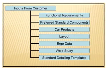
I) Function Requirement :- these are the requirements to meet a good finish produt as per customer design.
II) Preferred Standard Components :- While designing a BIW fixture we must have to use standard components like Cylinders,
Pins Locks as much as possible.
III) Car Product :- these are important data like Cad files, GD&T data and all.
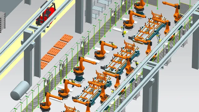
IV) Layout :- This layout helps a lot to manage space for robots and to develop a efficient robotic line.
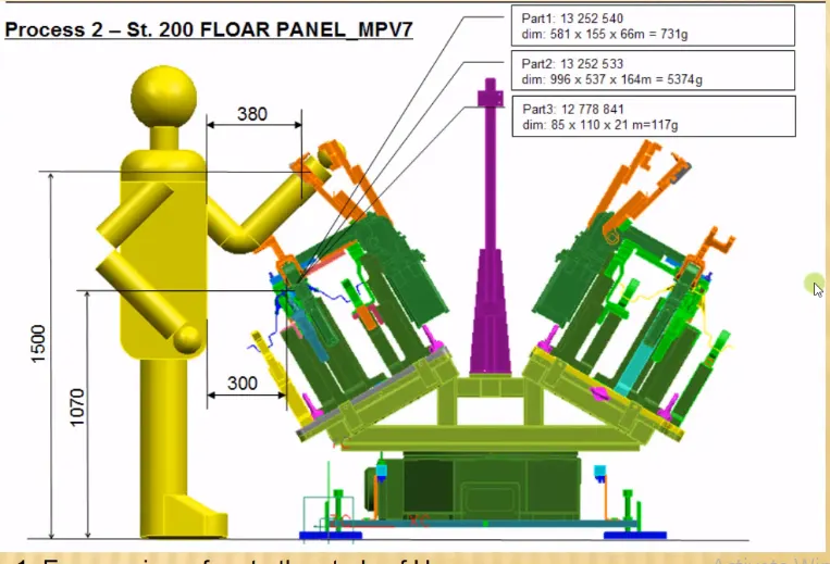
V) Ergo data :- The every industy has their own Ergo data for BIW, as per customer ergo data we have to proced for design.
for Ex - Heigh of fixture liver, position, tilting angle and etc.
VI) Weld Study :- Customer specifys the data about the wekding like - Weld type and position etc.
VII) Standard Detailing Templet :- Customer gives us standard detailing templete, so we can use that to detail or
diminesioning components according to that templete.
3) What is the input we get from "Car Products"?
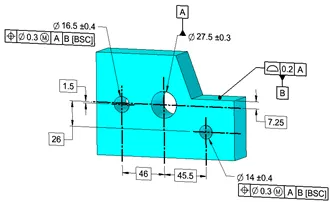
I) GD&T - in this custmer gives detaild dimesions along with geomatriical dimensions and tolarances (GD&T)
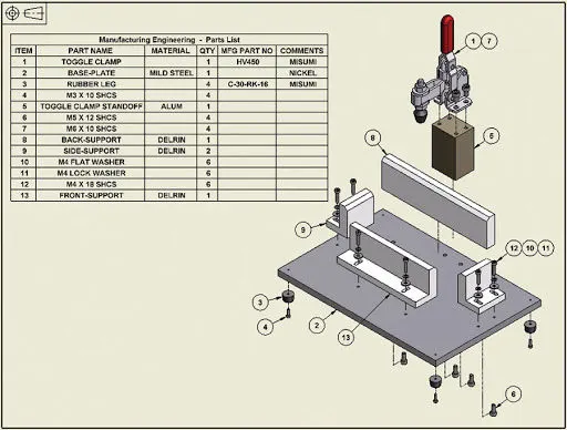
II) Part list - In an drawing, part list shows whole and sole data about part number, part description, material and quantity required for perticular assembly.
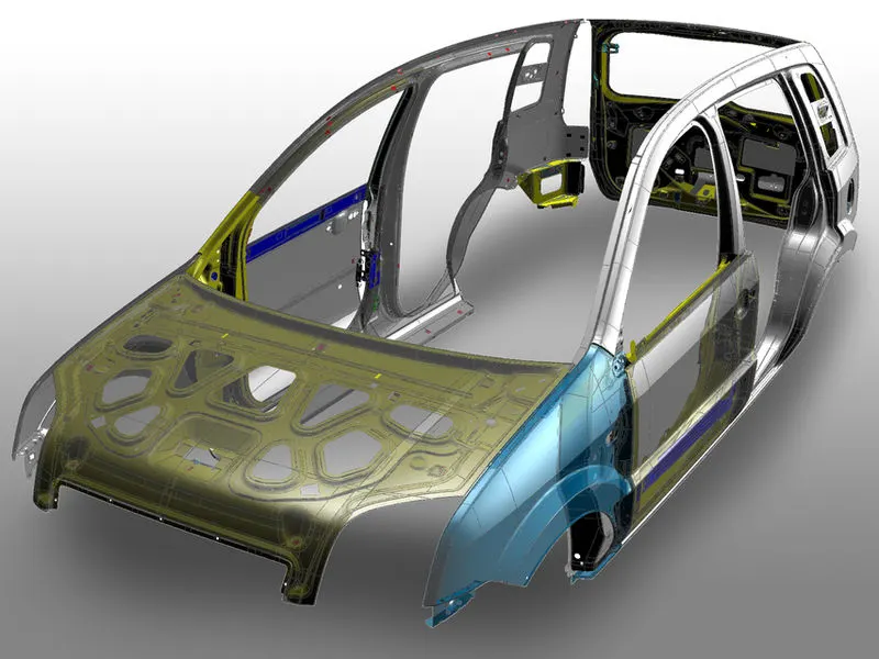
III) CAD file :- Cad file must required from customer to proced for BIW design.
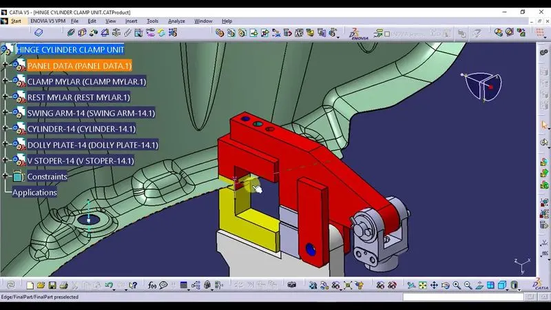
IV) Clamp plane :- The clamp sggested by customer according to their end design which we have to follow.
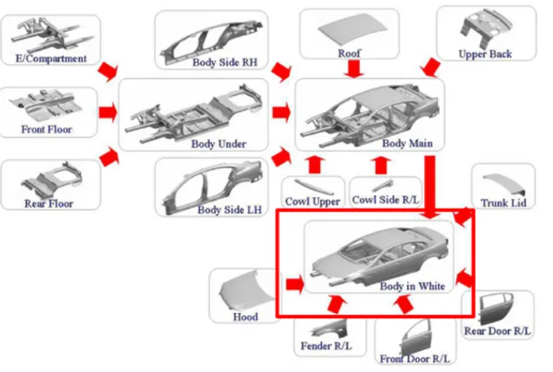
V) Product Assembly Process Sheet :- This is a process sheet which shows sequence of assemby and process.
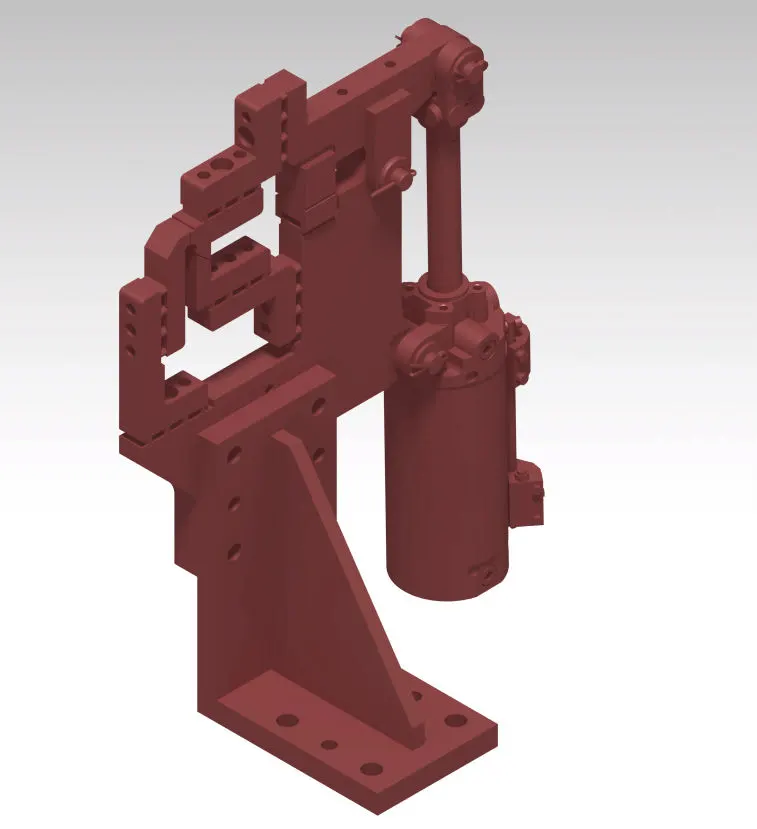
4) What is the Clamp plan?
Clamp plan provides the informtion of location of pins, Rest units, clamp unit, Dumps etc. It is the important input from
customer. The clamp plan/position should not be changed without the knowledge of customers.
5) What is the purpose of a Layout?
Layout refers to the way in which we organise the material which makes up the content of a design. The aim of layout is
both to present information in a logical, coherent way and to make the important elements stand out.
6) What is Ergo data?
Every company have standard ergo data and they provide it to fixture designer to design fixture considering that points
Ex. height of fixture is decided according to ease while working on fixture. So, we have to design a fixture by considering
safety, easy and fool proof design. Ergo Data is used to reduce human errors, increase productivity, human comfert and
safety.
7) What do you understand by Weld study?
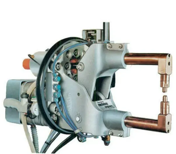
I) Weld gun details :- in this we understand about the Weld gun which is we are useing for pertcular point with respect
customer requiremnt about weld points.
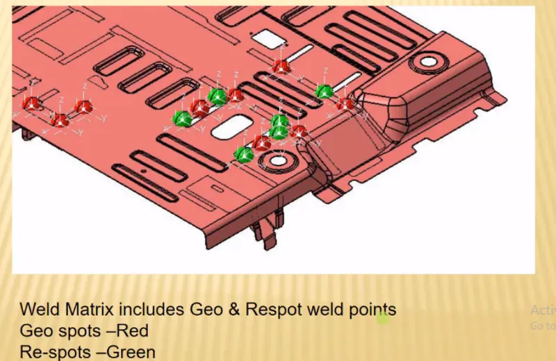
II) Weld matrix and weld points :- this includes the Geo weld points and Respot weld points.
a) Geo weld points :- The Geo weld points are which is planned in the Geo fixture.
b) Respot weld points :- The respot weld points are planned in the respot tool after Geo weld.
8) What are the criteria for percentage completion in the designing stage? Explain it in detail
The criteria percentage complition in design id a document to followup the project from
design to dispatch of project.
In this stage every single update have to be done in the document at every stage.
inthis mainly 4 stages are there as give below.
I) 0-25% (Input & Concept Design) :- this stage is a intial stage of project in which we design a concept of BIW and we check
fesibility
II) 25-40% (Concept Approval & Simulation) :- In this stage of fixture we have to send our concept drawing for approval
along with simulations and hence custome can under stand easily. and if customer is any corrections we have to go through it
and have to work further to resolve so that customer can get a good Fixture.
III) 40-85% (Design Freezing & Detailing) :- In this stage after solving all customer requirements we have to freeze the
drawing and start making Detailed draings.
IV) 85-100% (Check & Final Dispatch) :- In this stage we have check all quality requirements which required for customer
if required we can use CMM also to get better clarification, In the same stage fixture have to tested and finally have distach
with apropriate documentations.
9) Brief about "Output" in design?
The out put Design Contains lot of information about aperticula Fixture,
it inlude 2D and 3D models of fixture including part files and sub assembly also.
To submite a project to customer we have to all detailed drawing and models as output documentation.
This Design output classified as given below.
I) Unitized tools (multiple units on a common base) require two types of drawing sheets
* Key sheet - An index of units and their placements on the tool base
* Layout sheet -A detailed drawing of indibidual units to include all of their components
II) Non-unitized tools : Tools that can stand alone and can be detailed completely on a layout sheet. S G A A A
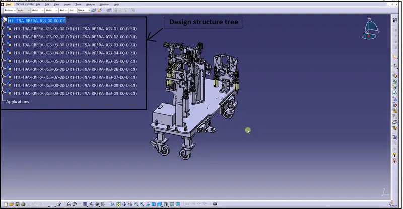
10) What do you understand by structuring a design tree? How does it reduce errors during the design process?
The tree strructuring is a important aspect in BIW design to avoide mistake while asssembly, inpection and at all stages
as given below in details
I) Structuring a design tree implies to a process where all the assemblies & parts are named in a specific standard. Different
customers have different set of standards to structure a design tree.
II) It is an important process which helps us to identify a specific part or assembly, as to which project,
tool or unit, it belongs to.
III) This helps us to avoid the errors during design study, manufacturing, assembly, inspection etc.
IV) If the parts or assemblies are not named properly or the design tree is not structured properly, it will create
confusion to understand the design & may create major possibilities of making an error.
V) Naming of a Fixture or a unit or a part, gives the information as to which project or zone or assembly do they belong.
It can help us to identify the quantity of items of same type or different types that are being used in an assembly.
11) What are Units? Mention 5 types of units.
unit is sub assembly or a ste of perticular parts.
In a BIW fixture all unites arrenged with respet to 3-2-1 principle of design.
5 types of units
1) Base unit - The base unit as its name shows it is vase for all units to hold and to support like valve box, automation unit, riser, mylars clamps and all.
II) Rest unit - as its name shows it is resting component in a BIW
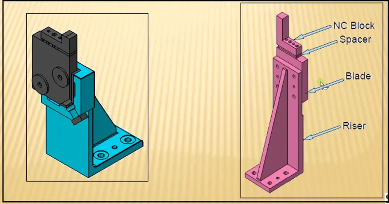
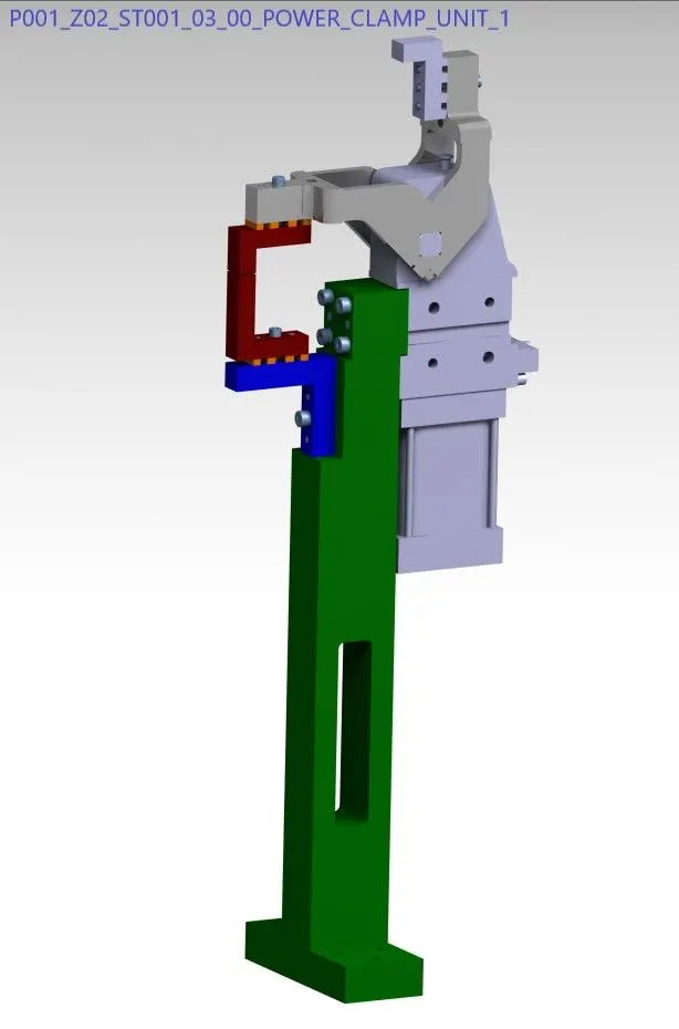
III) Clamp unit - Clamp unit is designed to clamp the components which have to weld in BIW,
The clamp unit includes NC blocks, mylars, fingers, sims, cylinders clamp arms and etc.
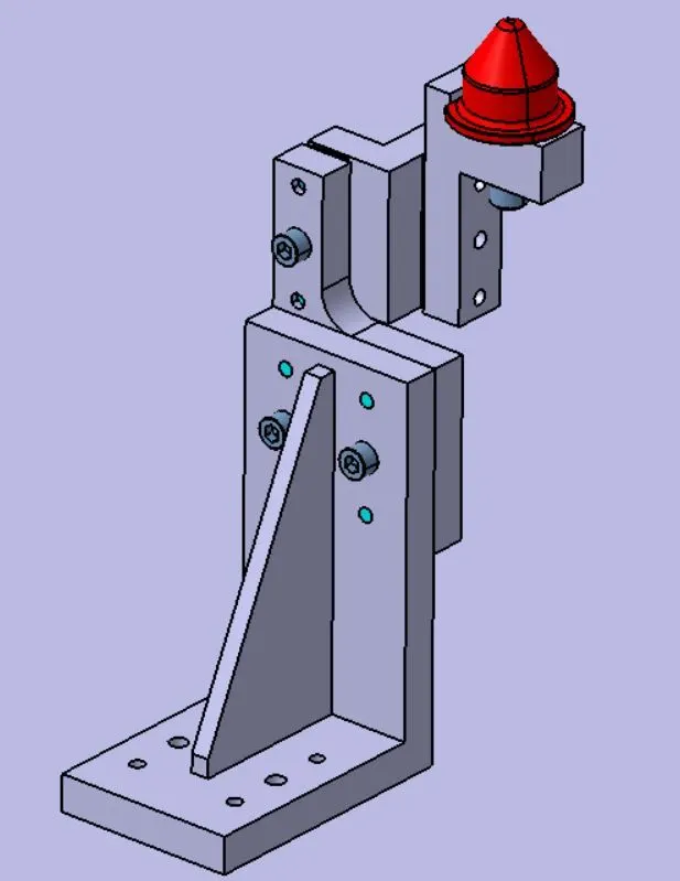
IV) Fixed pin unit - Fixed pin unit is a unit designed to locate the car panel using pins.table
Pin, pin retainer, shims, blocks, blade, riser are the part of fixed pin units, Pin retainer is used to hold the pin firmly.
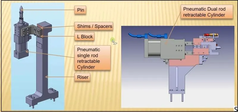
V) Retract Pin Unit - Retract Pin Unit having retracting unit which is used to move pin to ensure proper loading and
unloading of component.
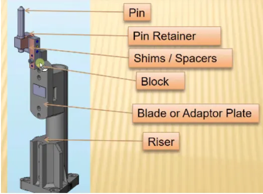
12) Describe Fixed Pin units & their purpose?
The fixed pin unit as its name shows it is afixed unit, in BIW we use to locate our panel.
This fixed pin unit contens Pin, pin retainer,Shims, block, blade and riser etc.
Purpose -
The main purpose of this pin it to locatote the panel and hold the panel with respect to 3-2-1 principle.
by using three fixed pin units we can arestes 6 degrees of freedom (4 axial & 2 radial)
The body part is constrained by a set of appropriately locating pin so total constraint by locating pin should be
fully constrained at all times to prevent any movement.
13) What are the different parts of a fixed pin unit?
I) Pin
II) Pin retainer
III) Shims
IV) Mylar
V) Blade
VI) Riser
Pin -
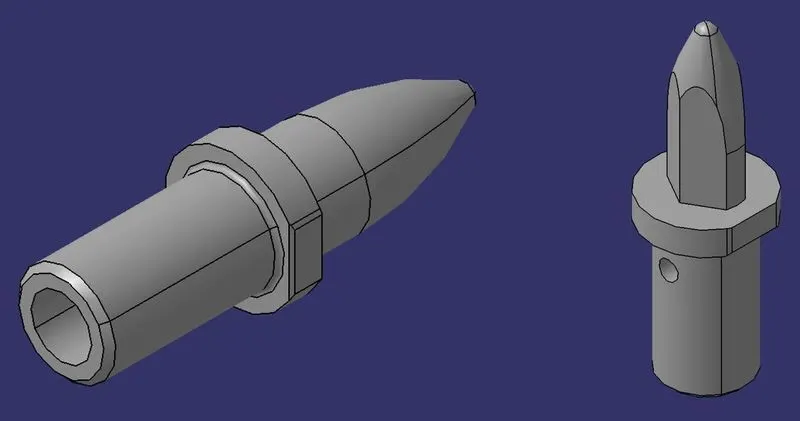
Pins are used to locking the rotational movement of the panel. Generally there two types of Pins, one is Round
Pin and another one is a Diamond pin. We use two and three-directional shimming for pins as per the angle
of the pin w.r.t. the carline. In some cases, we use a collared pin, when the pin is supposed to support the
panel as well. For this kind of pin, we provide 3 way shimming irrespective of pin angle to the carline.
Pin retainer
Pin Block is also called Pin Retainer. This block holds the pin and restricts the rotational motion of the pin.
Pin Block can be either manufactured one or Standard
Shims
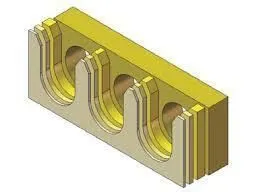
In general, a shim is a thin and often tapered or wedged piece of material, used to fill small gaps or
spaces between objects.
Shims are typically used in order to support, adjust for better fit, or provide a level surface.
Shims may also be used as spacers to fill gaps between parts subject to wear.
Shims are the small parts which comes with the thickness of 0.1mm, 0.2mm, 0.5mm, 1.0mm etc.
Mylar -
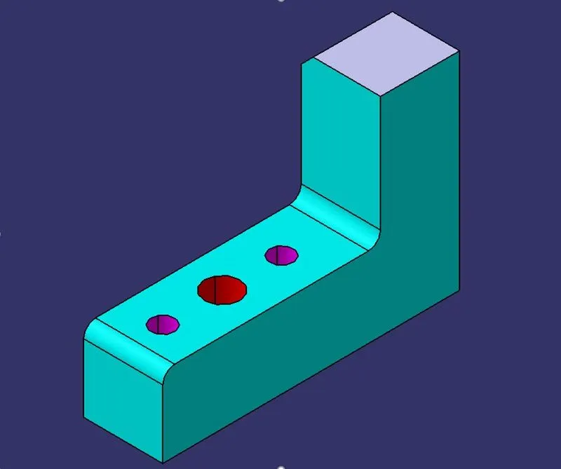
Mylar is one kind of block that touches the panel and holds or clamps the panel. Mylars are always
designed in CAR LINE. Mylar is also called NC(Numerically Controlled)Block. Mylars are mounted on
any block or plate with Shimming, So that height of mylar can be adjusted accordingly at the assembly
level. For ‘A’ class surfaces Nylon mylars are used. So that surface can be saved from scratches.
Blade
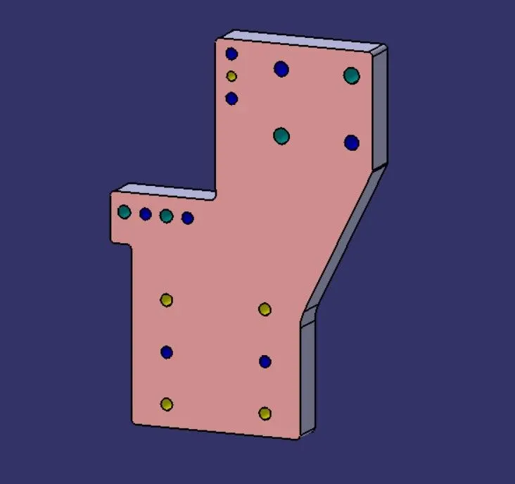
The plate which connects Riser to the Clamp cylinder is named Blade.
This plate plays an important role in building the unit. The plate can be of any shape,
But we need to keep in mind that the plate should be as compact as possible.
Riser
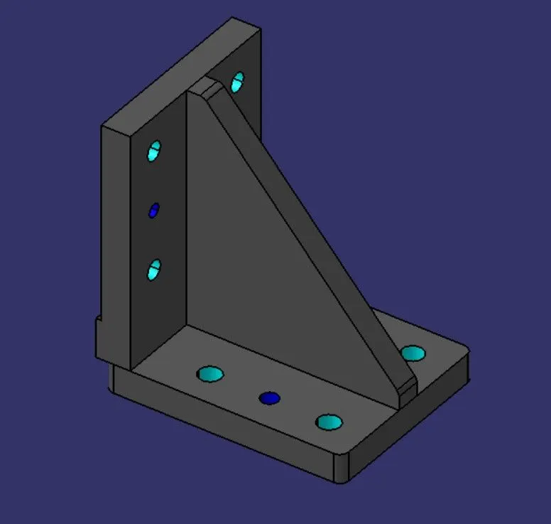
The part which is mounted on the base plate and holds a clamp or pin cylinder on it, is called Riser.
Riser can be Standard Part or manufactured part, it varies from project to project.
A riser can be a Single part or welded part. Standard risers also have various shapes and sizes.
14) What is the purpose of making a Rest unit & describe its parts?
Rest Unit is one of the simplest unit in fixture used with myler. As rest unit is simple to manufacture and
require low cost, hence rest unit is combine with clamp unit and location unit. Rest unit consist of following parts:
Mylar -
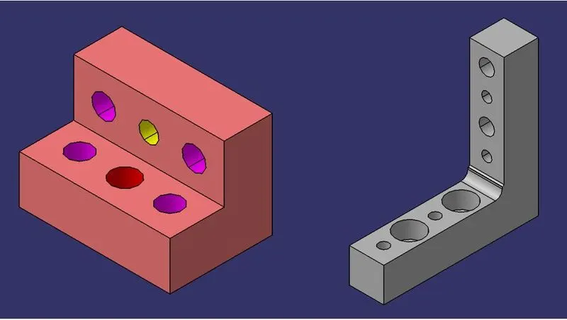
Mylar is one kind of block that touches the panel and holds or clamps the panel. Mylars are always
designed in CAR LINE. Mylar is also called NC(Numerically Controlled)Block. Mylars are mounted on
any block or plate with Shimming, So that height of mylar can be adjusted accordingly at the assembly
level. For ‘A’ class surfaces Nylon mylars are used. So that surface can be saved from scratches.
Shims
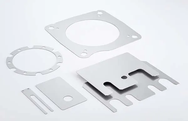
In general, a shim is a thin and often tapered or wedged piece of material, used to fill small gaps or
spaces between objects.
Shims are typically used in order to support, adjust for better fit, or provide a level surface.
Shims may also be used as spacers to fill gaps between parts subject to wear.
Shims are the small parts which comes with the thickness of 0.1mm, 0.2mm, 0.5mm, 1.0mm etc.
Blade
The plate which connects Riser to the Clamp cylinder is named Blade.
This plate plays an important role in building the unit. The plate can be of any shape,
But we need to keep in mind that the plate should be as compact as possible.
Riser
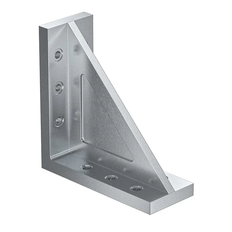
The part which is mounted on the base plate and holds a clamp or pin cylinder on it, is called Riser.
Riser can be Standard Part or manufactured part, it varies from project to project.
A riser can be a Single part or welded part. Standard risers also have various shapes and sizes.
15) What are the basic fundamentals to design a Sensor unit?
A sensor unit is a unit designed to sense the car panel by using Electrical sensors. This signals from the sensors
will be fed to the PLC and so the next process will be executed by this signal.
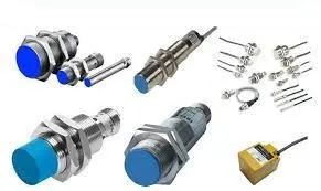
Fundamental of Sensor Unit design -
I) Every single loose panel which are being welded in a tool should be sensed.
II) Each panel should be sensed by 1 to 2 sensors depend on the size of panel, Preferred to be in diagonal
opposite ends of panel.
III) Every sensor should be mounted in a 3 direction adjustable way in general.
16) What is a Rough locator unit & what are the basic fundamentals to consider while designing it?
A Rough locator is a part designed to guide the operator, to locate the car panel on to the pins accordingly. A rough
locator can be of standard part or make part.
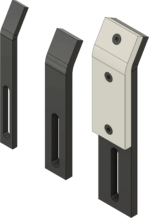
Fundamentals of Rough locator design -
I) Rough locators should be placed at the edges of the car panel, which it has to guide.
II) Rough locators has to be placed in the same angle of the car part edge with a minimum distance of 2-5mm
from the edge of the car part.
III) Rough locators should guide the panel in pin arresting direction.
IV) Rough locators should start guiding the panel before 10 to 15 mm to the start of the pin engagement.
V) Rough locators should be designed with entry angle for car part entry. .
VI) Rough locators should be designed with two slots to mount for easy adjustments.
VII) The slots should be in the direction of car part guiding.
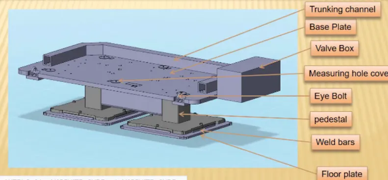
17) What is a Base unit and describe it's parts?
A base unit is the unit designed to mount all the other units (Clamp unit, Pin unit, rest unit etc.,) of the tool,
also other parts necessary for a tool like pneumatic valve box, trunking cable path will also be mounted on to a base unit.
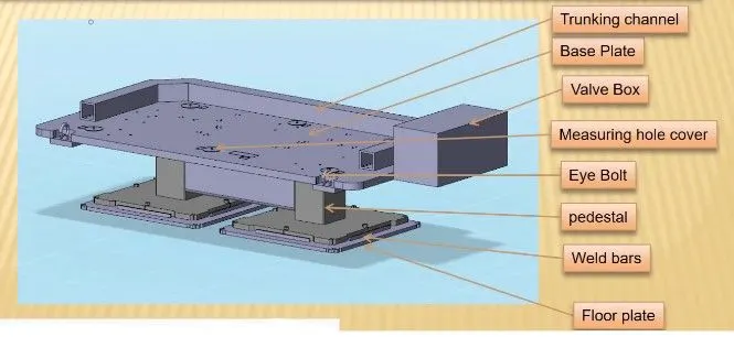
Parts description -
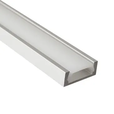
I) Trunking channel -
This is a hollow channle to provide cables supplies to respected sensors and valves units.
II) Base plate -
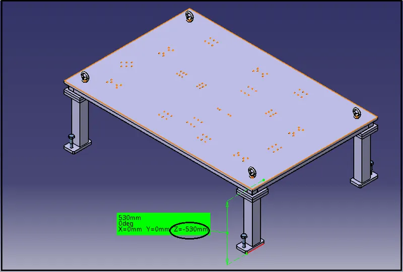
The base plate as its name shows, on its number of hole made to hold respected units ans all.
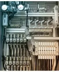
III) Valve box -
Valve box is nothing but a penumatic valve unit which used to supllu penumatic power to all actuators and valves as well as for some sensors also.
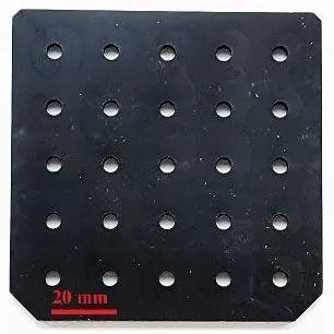
IV) Measuring hole cover -
On a base plate we have to make co-ordinates referance hole to measure all other hole. these hole are importnat while measuring and as well as assembling, so we have protect these holes rom damage so we insert a hole cover.
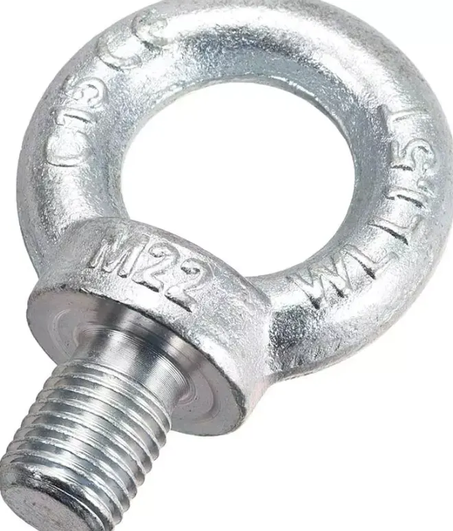
V) Eye bolt -
These eye bolts are inserted for lifring purpose while assembling and QC checking time.
VI) Pedestal -
The pedestls are supports for Base plate which holds and suports, to adjust height also.
VII) Floor paltes -
Floor plates are like common plates which use to while fixing a BIW on a floor.
18) What is a Dump Unit and what are its functions?
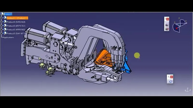
A dump unit is unit whic installed in BIW to assemble a Compex part.
Function -
Due to space constrain dump unit used in fixture. It has dump cylinder having open and close position for better understanding of design. It also has clamp cylinder used for clamping purpose, hence this is too complex unit to built.
19) What is a Slide unit? Mention where Slide units are commonly used.
The simple pneumatics is combined for advantages of automation, These integrated
drives are the perfect solution for all. An electric alternative for very simple movement and positioning tasks between
two mechanical end positions, but don't want the commissioning process for traditional electric drive systems that can often
be quite complex.
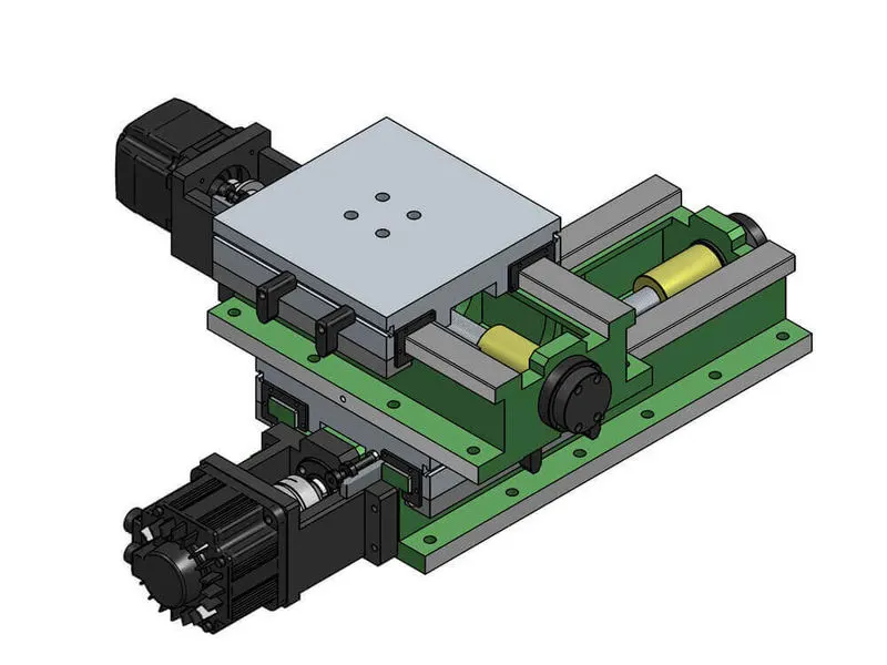
This unit consist of sliding rail on which entire unit is slide in direction of rails for further operation. Sliding unit
consist of open and close position.
The simplicity of pneumatics is now combined for the first time with the advantages of electric automation, These integrated
drives are the perfect solution for all. An electric alternative for very simple movement and positioning tasks between
two mechanical end positions, but don't want the commissioning process for traditional electric drive systems that can often
be quite complex.
Slide units are used in -
I) Mostly in complex fixture where the sliding mechanism will be involved.
II) some space constraints in locating the panel, heence Slide application will be easy for welding.
III) Used into posiotion fixtures,
IV) weldgun and robots.
V) Used in automotive industry for different types assembly lines and etc.