Week 3:- BiW Fixture Design Methodologies Challenges
Design methodologies is one of the pre design process which is the steps followed during the concept designing phases in fixture design.
fig-shows the various categories in Design methodologies
- Categories are described below
(1) Purchase order -
- A purchase order, or PO, is an official document issued by a buyer committing to pay the seller for the sale of specific products or services to be delivered in the future.
- A PO specifies-
- Quantity purchased
- Product or service being purchased
- Specific brand names, SKUs, or model numbers
- Price per unit
- Delivery date
- Delivery location
- Billing address
- It officially confirms to start the work on the design.
(2) Inputs from customer -
- Designer needs following basic information to start the BIW fixture
- First understand scope of the work. Means what is expected by customer. Every customer has its specific requirements and it may have own raw material, electric, pneumatic,cad, design standards.Every customer also gives different inputs and expects output e.g 2d drawing, process sheet in xls, pdf, CAD format of design, layout format, OLP.
- Bill of material (BOM) of the components to be welded- spot welding
- CAD panel data or at least 2D drawing of assembly and individual panel data
- Sheet metal panel thickness.Plays major role to decide 2 metal or 3 metal weld.
- Spot Detail information like total no of spots and spacing between the spots.
- Weld information clarity from drawing like 2 metal or 3 metal welding
- PLP (Principle location scheme) of the individual panel and total assembly.
- Cycle time - if calculated or can be found out as per manual or robotic welding process.
- Process sheet if Process engineering is done - where loading sequence, no of clamp data and gun data is mentioned.
- All clamping cylinder and fixtures standards.
- CAD -Software guidelines
- Raw material standards
- Design guidelines
- Bought out item(Purchased parts) standards like pneumatic items, toggle clamp, bearing, screw, dowel etc company information
(3) Percentage completion Criteria -
- It consist planning of completion of total project. How much days the project will take to complete.
- It is followed in designing stages & dispatch stages of the welding fixture.
- it ensures that how much task that we have decided to complete within the stipulated time is complete or not & how much of it is rest to complete & wheather it is going to be complete or not in given time.
(4) Design Output -
- Output consist 3D models,2D drawing which is the detailing part, BOM & other related documents.
- There are some tools which are multiple units on common base are called inutized tools for ex. fixture which includes no. of units on the same base.
- They required two types of drawing sheet as follows,
1)key sheet- It shows the index of the unit & their placement on tool base
2)Layout sheet- It is the detailed drawing individual unit to include all their components.
- Non unitised tools which can be completely detailed on layout sheet.
2)What are the inputs required from the customer to start designing a Fixture?
- The following are the inputs we required from the customer to start the fixture design work.
A) Functional requirement - It is the basic requirement which defines the function of the fixture wheather it is being used for welding, Hemming, Checking fixture or storage racks. Depending on this the design considerations are going to change while designing the fixture.
B) Preffered Standards - The customers wants to follow some standards. These standard parts which we can use as it is in our design which saves our project time & money as well.
ABB, NAAMS, TUNKERS, ZYTRAN, DESTACO are some standards.
Some standard parts like riser. L-Blocks,Retainers etc.
Some components like Clamps, Cylinders, Switches, Sensors etc.
C) Car Products - It includes following inputs from customer
a) GD & T - Geometric dimensioning & Tolerance of the part for which the fixture have to be designed. GD & T provides information about Locating pins, Rest, Clamp, Dumps & slides information of each station & Sequence & opening of clamps, Dumps & slide stroke information.
b) Part List - This is the list of part which are going to assembled in the fixture. It includes information about the part name, Part number, Tooling revision, Part thickness etc.
c) Cad files of part - The 3D model file of the car part designe by using modelling software is given from the customer.
d) Clamp plan - This is the clamping plan of the part whicle doing the operation. We can not change th eclamp plan without the permission of the customer. It is very important input from the customer. It provides location of pins, Rest, Clamps, Dumps etc.
e) Product assembly process sheet - It gives detail process of the completion of the part from scratch to the finished product assembly.
D) Layout - Layout provides information about Flow of parts, Station pitch, Robot stations, Tool changers, Tip dressers, Platform height, Sub asselmbly links & loading/Unloading sequence.
E) Ergo Data - It is the study of human behaviour & movements during the assembly work. It provides data regarding loading height, working safety zone of the operator etc.
F) Weld study - It includes the study of the weld gun is going to be used for th operation depending on the size of the part, Thickness of the part etc. It also includes the study of the weld matrix & the weld point positions. There are two types in weld point one is geo weld points which ensures the geometry of the assembly & second is the Re spot weld points which adds strength to the already welded point.
G) Standard detailing templates - Every customer have their standard of detailing & the templates which are used for 2D drawing & detailing.
3)What is the input we get from "Car Products"?
- Following is the input we get from the car products
a) GD & T - Geometric dimensioning & Tolerance of the part for which the fixture have to be designed. GD & T provides information about Locating pins, Rest, Clamp, Dumps & slides information of each station & Sequence & opening of clamps, Dumps & slide stroke information.
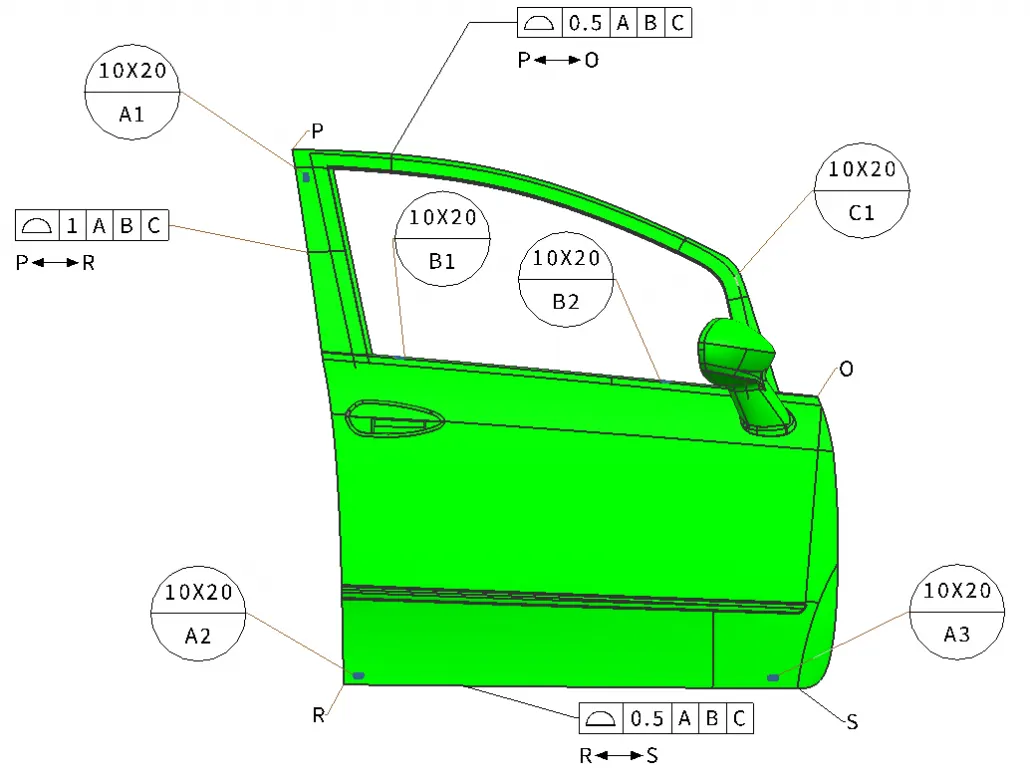
Fig-shows Car door with surface profile tolerances to ensure optimal assembly
b) Part List - This is the list of part which are going to assembled in the fixture. It includes information about the part name, Part number, Tooling revision, Part thickness etc.
fig-shows part list of assembly
c) Cad files of part - The 3D model file of the car part is given from the customer to study on it.The car part is designed by using 3D modelling software.From this we can get some conceptual idea of the designing of fixture. The model is going to be the base of the fixture design.
d) Clamp plan - A clamp is a force-actuating mechanism of a fixture. The forces exerted by the clamps hold a part securely in the fixture against all other external forces. Clamping surfaces are subjected to the clamping forces for obtaining invariant location. Clamp plan is the Clamping plan of the part while doing the operation. We can not change the clamp plan without the permission of the customer. It is very important input from the customer. It provides location of pins, Rest, Clamps, Dumps etc.
e) Product assembly process sheet - It gives detail process of the completion of the part from scratch to the finished product assembly. We can get details like the no of steps involved in the assembly process & Sequence of opeartion.
fig-shows the process sheet of rack assembly
4)What is the Clamp plan?
- A clamp is a force-actuating mechanism of a fixture. The forces exerted by the clamps hold a part securely in the fixture against all other external forces. - Clamping surfaces are subjected to the clamping forces for obtaining invariant location.
- Clamp plan is very important input from the customer. the Clamping plan of the part is the plan which defines the location of the clamp while doing the operation to ensure the geometry of the assembly.
- We can not change the clamp plan without the permission of the customer.We have to design fixture which should not required change in the clamp plan.
- It provides information regarding to the location of pins, Rest, Clamps, Dumps etc. The coordinates is also mentioned in the clamp plan so the design team can take the cordinates directly & start the designing of the fixture.
fig-shows the clamp plan
5)What is the purpose of a Layout?
- Layout is the most effective physical arrangement, either existing or in plans of industrial facilities i.e. arrangement of machines, processing equipment and service departments to achieve greatest co-ordination and efficiency of 4 M’s (Men, Materials, Machines and Methods) in a plant.
- Plant layout is a floor plan for determining and arranging the designed machinery and equipment of a plant, whether established or contemplated, in the best place, to permit the quickest flow of material, at the lowest cost and with the minimum handling in processing the product, from the receipt of raw material to the shipment of finished product
- It shows all the objects of manufacturing line like robots, Fixtures, Racks etc. & also shows the reacheability of the robot to the fixtures also called the swept area of the robot. It also shows the constraint of space or the space available for the fixture that we are designing.
- Layout provides information about Flow of parts, Station pitch, Robot stations, Tool changers, Tip dressers, Platform height, Sub asselmbly links & loading/Unloading sequence.
fig-shows the layout
6)What is Ergo data?
- Human factors and ergonomics (commonly referred to as human factors) is the application of psychological and physiological principles to the engineering and design of products, processes, and systems. The goal of human factors is to reduce human error, increase productivity, and enhance safety and comfort with a specific focus on the interaction between the human and the thing of interest.
- The final assembly of an automobile involves tasks of complex nature. These processes are on the least priority for automation. Manual labor is best suited for assembly operations with the aid of minimal level of automation. All the processes have to be improved continuously in order to reduce the costs and increase productivity .
- The workers attain various postures, exerts force and works continuously in cycle time to accomplish the assembly task. Working along automobile assembly lines is characterized by repetitiveness.
- Ergo data is studied to identify and quantify ergonomics working postures that contributed to the serious development of muscle skeletal injuries and thus investigated possible contributory their related causes.
fig-shows the science of designing user interaction with equipment and workplaces to fit the user.
fig-shows indian atmospheric human data
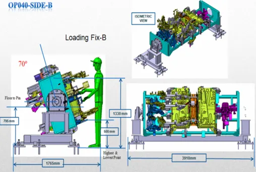
fig-shows the ergo data for the operator working on the fixture
7)What do you understand by Weld study?
- Welding is predominantely used in automobile industries and requirements for fixtures that ease the welding process is a continuous development task in any industry.
- Car Body-In-White (BIW) is a complicated steel-structure including 300~500 sheets with complex shape and are assembled by means of welding in a high rhythm through 55~75 robotic work-stations.
- The foremost step taken before starting the design of welding fixture is to arrive at the spot weld locations. The location and orientation of other critical units of the fixture including clamps, locators etc., are decided based on the weld spot distribution. The weld spots for Front door inner panel - side bracket assembly are located as shown in Table 1 with respect to the body line of car.
table shows the weld point distribution
fig-shows spot weld part details
- It includes the study of the weld gun (A portable device for semiautomatic welding of parts of various articles) which is going to be used for the operation depending on the size of the part, Thickness of the part etc.
- It includes the study of the weld matrix & the weld point positions. There are two types in weld point one is geo weld points which ensures the geometry of the assembly & second is the Re spot weld points which adds strength to the already welded part.
8)What are the criteria for percentage completion in the designing stage? Explain it in detail
- The % Completion criteria contain the current status of a task, expressed as the percentage of the task's duration that has been completed. You can enter percent complete, or you can have Project calculate it for you based on actual duration.
-It consist planning of completion of total project. How much days the project will take to complete.
- It is followed in designing stages & dispatch stages of the welding fixture.
- it ensures that how much task that we have decided to complete within the stipulated time is complete or not & how much of it is rest to complete & wheather it is going to be complete or not in given time.
- When a task is first created, the percent work complete is zero percent. If you enter actual work for the task, Project calculates percent work complete as follows:
Percent Work Complete = (Actual Work / Work) * 100
- In a typiacal BIW fixture design we can consider the following criteria of recentage completion,
(a) Input & concept design- 0 to 25%
The design inputs from the customer & after studying those inputs the concept fixture designs are created.
(b) Concept approval & Simulation check- 25 to 40%
The concept design approval from the customer after study of simulation.
(c) Design freezing & detailing- 40 to 85%
After the simulation result if no any changes are required then the design is freezed. After freezing the 2D drwaing which is the detailing part is started.
(d) Check & final dispatch- 85 to 100%
After detailing the quality checking team start inspection of all the data & it will dispatch to the customer if everything is ok.
9)Brief about "Output" in design?
- Each manufacturer shall establish and maintain procedures for defining and documenting design output in terms that allow an adequate evaluation of conformance to design input requirements. Design output procedures shall contain or make reference to acceptance criteria and shall ensure that those design outputs that are essential for the proper functioning of the device are identified. Design output shall be documented, reviewed, and approved before release. The approval, including the date and signature of the individual(s) approving the output, shall be documented.
- The outputs of design and development shall be provided in a form that enables verification against the design and development input and shall be approved prior to release.
Design and development outputs shall
a) meet the input requirements for design and development,
b) provide appropriate information for purchasing, production, and for service provision
c) contain or reference product acceptance criteria, and
d) specify the characteristics of the product that are essential for its safe and proper use.
- A Design Output is a drawing or specification or manufacturing instruction. Design Outputs describe all the components, parts, and pieces that go into your medical device. Design Outputs describe all assemblies and sub-assemblies of your product.
- Think of it like this. If you were tasked with assembling a fixture from scratch, what documentation would you need to do so? All this documentation that you would need--Design Outputs.
- Output consist 3D models,2D drawing which is the detailing part, BOM & other related documents.
- There are some tools which are multiple units on common base are called inutized tools for ex. fixture which includes no. of units on the same base.
- They required two types of drawing sheet as follows,
1)key sheet- It shows the index of the unit & their placement on tool base
2)Layout sheet- It is the detailed drawing individual unit to include all their components.
- Non unitised tools which can be completely detailed on layout sheet.
- The output should compile following point-
1) Approved standard parts should beused wherever possible.
2) Deisgn should be as simple & economical as possible.
3) Design must comply with all safety & economic standard.
4) Design must provide for controlled & damage free handling of product
5) Adequate error proofing provision must be encorporated in each design by providing proximity switches, Rough locators etc.
6) The weight of moving part must be kept to minimum while maintaining maximum strength.
7) Frames & structures are to be simple & sturdy.
8) Design clearance & accesibility for routine maintainance & service.
9) Motion control must be considered on any moving component.
10) Designer is resposible to validate all clamps & weld guns.
10)What do you understand by structuring a design tree? How does it reduce errors during the design process?
- Structuring a design tree implies to a process where all the assemblies & parts are named in a specific standard. Diffrent customers have their different set of standards to structure a design tree.
- It is an important process which helps us to identify a specific part or assembly as to which project, tool or unit, it belongs to.
- This helps us to avoid the errors during design study, manufacturing, assembly, inspection etc.
- If the parts or assemblies are not properly or the design tree is not structures properly, it will create confusion to understand the design & may create major possibilities of making an error.
- Naming of a fixture or a unit or a part, ives the information as to which project or zone or assembly do they belong.
- It can help us to identify the quantity of items of same type or differnet types are being used in assembly.
fig-shows the design tree in which designed parts are at top & all standard parts are at bottom
- The blue highlighted number is
H1L-T9A-RRFRA-JG3-00-00-00
It can be bifurgate as follows,
H1L-T9A- The project name
RRFRA- Panel name
JG3- Jig no. 3
00- Unit no.
00- part no.
00- Component no.
- Under the product there are main assemblies, Sub assemblies, Child part, Standard parts etc. these all parts are provided with specific no, Zone etc. to identify easily.
11)What are Units? Mention 5 types of units.
- A unit is a device that has a specified function, especially one forming part of a complex mechanism.
- The BIW fixtures is the assembly of different units which are designed to fulfill different purpose.
- The unit have the specified function like resting the panel, clamping the part, Locating the part etc.
- According to the 3-2-1 principle of fixture design the units are designed to locate & clamp the car panel to its specified positiion in fixture while operation is going on.
- In the following the different units are showed by different color.
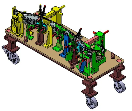
fig-shows entire BIW fixture tool
fig-shows the clamping unit from the BIW fixture
- following are the typical types of units used in BIW fixture design,
1) Fixed pin unit- It is non movable locating unit used for proper location of the part
2) Retract pin unit- It is movable locating unit.
3) Rough locator unit- It roughly guides the operator for locating the part.
4) Rest unit- The panel is rest on this unit.
5) Base unit- It is the unit on which all other units are mounted.
12)Describe Fixed Pin units & their purpose?
fig- shows the fixed pin unit & its parts
- Fixed pin unit consist of riser, blade, block, shims or spacer, pin retainer & pin.
- Riser is the standard part which is used to rise up the height of the while unit. Blades are plates mounted on the riser. Other parts like cylinder, arms etc are mounted on the blade.
- Shims are the small part which comes with the thickness of 0.1mm, 0.2mm, 0.5mm etc. These will compensate the stackup tolerance which reflects at the panel holding part called Mylars. In fixed pin shims are used to adjust to traslational motions.
- Pin retainer will support the pin & the locating pin which restricts movement of the car panel.
Purpose of fixed pin unit-
- Fixed pin unit is a unit designed to locate the car panel using pin.
- The fixed pin unit is the part of the 3-2-1 principle. It restricts 6 degrees of freedom of the car panel.
- It is necessary to have 2 pins to locate car panel. one pin must arrest 4 way (4 translational ) & other must arrest 2 way (2 rotational ) of a car panel.
13)What are the different parts of a fixed unit?
- Fixed pin unit consist of riser, blade, block, shims or spacer, pin retainer & pin. All parts are described below.
1) Riser- Riser is the standard part which is used to rise up the height of the while unit.
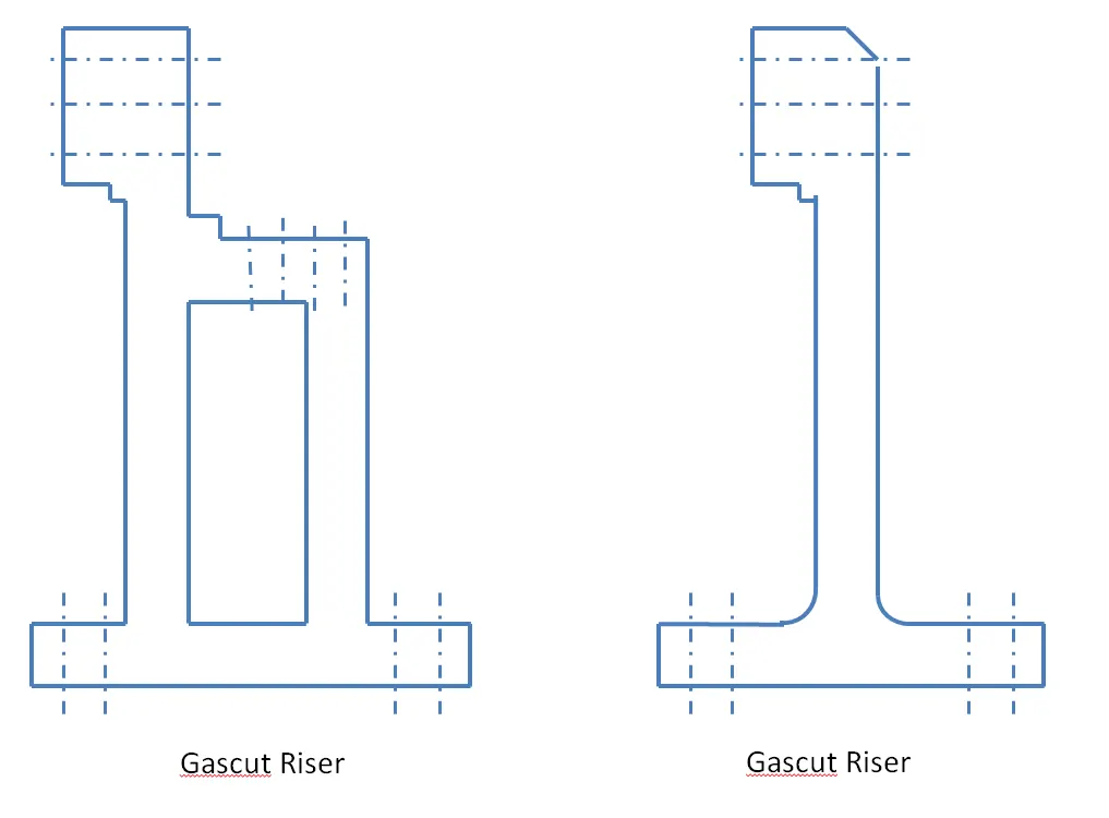
fig-shows the riser
2)Blades - These are plates mounted on the riser. Other parts like cylinder, arms etc are mounted on the blade.
3)Shims- These are the small part which comes with the thickness of 0.1mm, 0.2mm, 0.5mm etc. These will compensate the stackup tolerance which reflects at the panel holding part called Mylars. We give tolerance to all the parts of the fixture. Due to this tolerance the Mylars will either lift up or goes down from its defined position. If the Mylars goes down from the defined height it will make impression or dent on the panel. If the Mylars lift up then there will be a distorsion due to welding stress. To adjust the Mylars At its defined position we use shims so the panel won't deformed & also dont get any impression on it.
4)Pin retainer - It will support the pin.
5)Locating Pin- Typically, locating pins are used for controlled, fine tolerance positioning of a work piece. For example, a pallet that is moved along one axis, where the drive mechanism is not accurate and stable enough to place it in a position sufficiently accurate to execute a particular process, the use of locating pins may be the best solution.
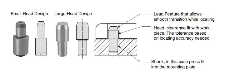
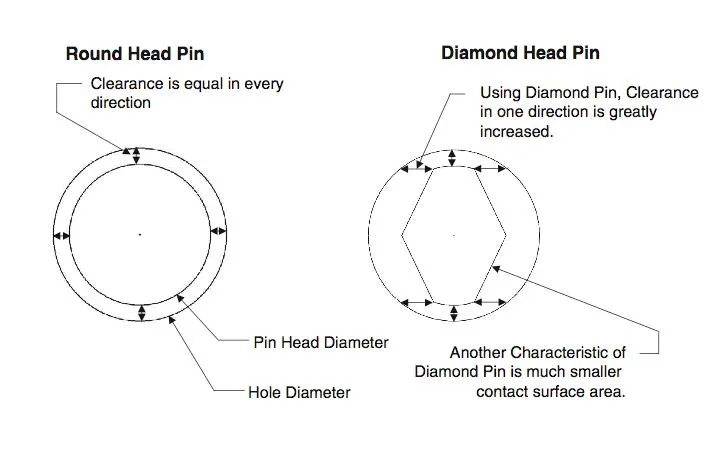
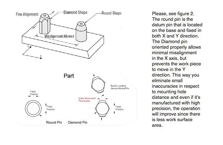
- The Diamond Shape is a critical feature that helps with machining inaccuracies and smoother locating operation. When two round head pins are installed onto one plate, the distance between two mounting holes must be extremely precise and even then, the work piece will not be placed on the base as easily as it would with the use of a diamond shape pin.
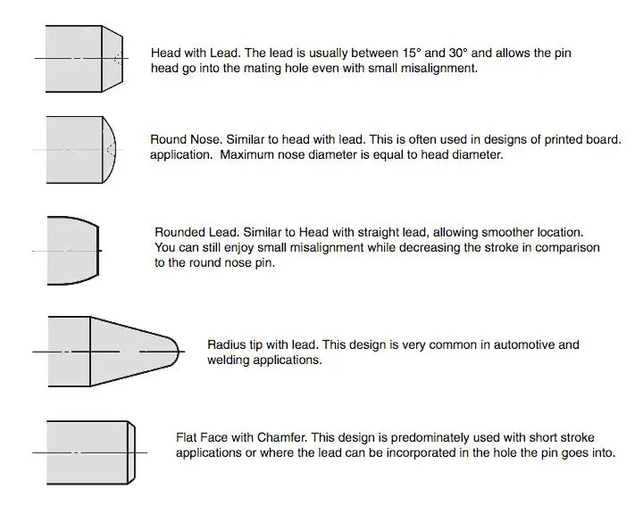
- There are several styles of Pin Head shapes. They serve different purposes and can be utilized in a variety of applications.
- The rest units are designed to rest/support the car panel by using NC blocks/Mylar/Rest
- It is the simplest unit to design because it have less parts to design & the purpose is only resting of the car panel.
- Because of this simplicity the rest unit is combined with other unit to reduce the cost of the overall project.
-It can be combined with clamp unit to clamp as well as to rest the car panel. It can be combined with locating unit to locate as well as to rest the car panel. also locating, clamping & restunit can be combined together in one unit to reduce cost.
fig-shows the rest unit 2D
fig-shows the combined locating, clamping & resting
unit to reduce the cost.
it consist following parts,
1) Riser- Riser is the standard part which is used to rise up the height of the while unit.
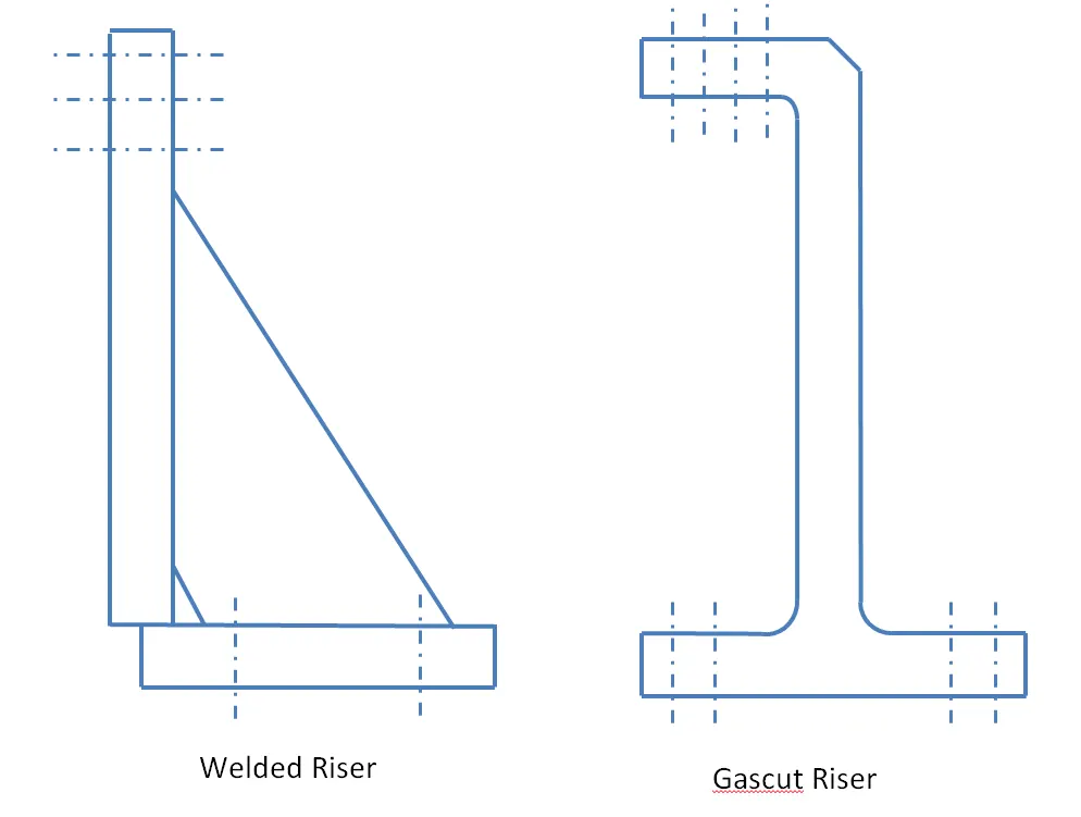
fig-shows the riser
2)Blades - These are plates mounted on the riser. Other parts like cylinder, arms etc are mounted on the blade.
3)Shims- These are the small part which comes with the thickness of 0.1mm, 0.2mm, 0.5mm etc. These will compensate the stackup tolerance which reflects at the panel holding part called Mylars.
Shims are used in one in direction in rest unit which is up & down because it requires adjustment in height only.
4) NC blocks/ Mylar/Fingers- Mylars is the component which holds the panel while operation. These are placed from top side & from bottom side also. The top side Mylars called as Clamping Mylars & the bottom side Mylars called as Resting Mylars. Every clamping Mylars have resting Mylars. It dont allow deformation of the part due to welding stresses.
fig-shows mylar/NC blocks
15)What are the basic fundamentals to design a Sensor unit?
- Sensor is a device which detects or measures a physical property and records, indicates, or otherwise responds to it.
- A unit designed to sense car panel using electrical sensors is called sensor unit. The from the sensors is send to the PLC so the next process is executed by this signal.
- The sensor is very sensitive & easily damagable part so sensor cover is provided to the sensor for safety purpose.
- There are different types of sensors
a)proximity sensor
b)laser sensor
c) photo electric sensor
d) Infrared sensor etc.
fig-shows the sensor in side unit
- Fundamentals of sensor unit design-
1) Every single loose panel which are being welded in a tool should be sensed.
The assembly of car panel consist of no. of panels. The location of every panel is fixed. There are some locating units, clamping unit,rest unit etc, are provided for proper location & operation. The sensor is attached in this unit to sense the part is loaded or not. If the part is not loaded the sensor will send negative signal to the PLC controller & operation will not start & viceversa. Hence every single loose part should have at least 1 sensor.
2) Each panel should be sensed by 1 to 2 sensors depends on the size of panel, Preffered to be in diagonal opposite ends of panel.
sensor is used to sense the part is loaded or not & starts the operation by sending the positive signal. But if the part is big in size then there will be 2 sensors required because the part will be loaded in correct position at one end & will be not positioned correctly at other end & due to which the the assembly will not be ok part & gets rejected at QC check stage. Hence to neglect these kind of situations the part should be sensed by 1 or 2 sensor depending on its size for proper assemly.
3)Every sensor should be mounted in a 3 direction adjustable way in general.
Sensor can be adjusted to the particular distance from the panel by using these 3 directional adjustable way. If we use proximity sensor it have range 5 to 10mm to sense part & for laser sensor the range increases.
16)What is a Rough locator unit & what are the basic fundamentals to consider while designing it?
-- A rough locator is a part designed to guide the operator, to locate the car panel on to the pins accordingly. A rough locator can be of standard part or make part.
fig-shows rough locators of diffrent shape
fig-shows the rough locator in combined unit of clamping & locating
- It can be called as fool proofing method also. Because due to the rough locator the part cannot be loaded in correct position. The rough locators are set according to the angle of the respective panel hence part can only be loaded in defined direction & orientation.
Fundamentals of rough locator design-
1)Rough locator should be placed at the edges of the car panel, which it has to guide.
2)Rough locator has to be placed in the same angle of the car part edge with a minimum distance of 2-5 mm from the edge of the car part.
3)Rough locator should guide the panel in pin arresting direction.
4)Rough locator should start guiding the panel before 10 to 15mm to the start of the pin engagement.
5) Rough locator should be designed with entry anglle for the car panel. Generally it ranges between 30-45 degree.
6)Rough locator should be designed with two slots to mount the easy adjustments.
7)The slots should be in the direction of car part guiding.
17)What is a Base unit and describe it's parts?
- A base unit is the unit designed to mount all the other units(Clamp unit, Pin unit, rest unit etc.) of the tool, also other parts necessary for a tool like pneumatic valve box, trunking cable path will also be mounted on to a base unit.
fig- shows the base unit with its components
fig1- shows fixed base unit
fig2- shows the movable base units
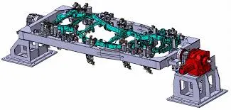
fig3-shows the rotating base unit.
- Base unit is the fundamental componet of the fixture because all other components are mounted over it.so every fixture have base unit. The base unit design is different according to the panel, Design of clamp system, location system etc.
- Fig1 shows fixed base unit which is fixed to the floor by using nut bolts.
- Fig2 shows movable base unit which can be moved from one place to another by using the wheels provided.
- Fig3 shows the rotating base unit. In this the base is fixed at two ends but the fixture can be rotate aroung its horizontal axis by using some rotating mechanism.
parts included in base plate are described below
1)Floor plate- It is the plate which join the fixture to the floor by using some nut bolts. This plate surface is machined for maintaining the horizontal position of the fixture.
2)Weld bars & pedestal- Pedestal is the base or support on which a The fixture is mounted.
3) Eyebolt- An eye bolt is a bolt with a loop at one end. They are used to firmly attach a securing eye to a structure, so that ropes or cables may then be tied to it.
eye bolt with nut heavy forged eye bolt with shoulder
Machinery eye bolts are fully threaded and may have a collar, making them suitable for use with angular loads up to 45°. Eye bolts without a shoulder should not be used for angular loads.
Heavy forged eye bolts with a continuous eye may be forged with an integral shoulder, allowing their use for heavy off-axis loads.
4) Measuring hole cover - The base plate have some drills to mount various units like clamp, rest, pin etc. & every drill have some coordinates to define the exact location of the hol. Due to irregular shape of the car panel the drilled holes coordinates are not like 110.0, 150.0 But it like 110.62,150.84. The maesuring hole is drilled over the base plate which having exact cordinates so that all other holes can take reference from it. The measuring hole no. depends on the size of base plate. These holes are covered by using some plate to protect against dust, damage etc.
5) Valve box & trunking channel- The valve box is the box which includes different solenoid valves. The pneumatic fixtures work on air pressure provided to it. So the arrangement of air pressure inlet & outlet is done within this valve box. The trunking channel includes all the pressure inlet cables going to the pneumatic parts of the fixture & protects them from damaging while operation is in process.
6) Base plate- Base plate is the heavy plate of large thickness becuase it carries all the weight of the mounted parts. So it must be able to bear the load. Base plate is machined to maintain the parallelity within the tolerance. It also consist some drilled holes to mount the different units over it.
18)What is a Dump Unit and what are its functions?
- When we have some geometrical constraints then we can not mount normal units like clamp unit, pin unit etc. In this case the dump unit is used.
- Dump unit is the complex unit to design due to space constains there is less space avilable & have to adjust all the parts in available space.
- It consist of dump cylinder to perform the operation of clamping & unclamping car panel.
-
-
fig-shows dump unit
19)What is a Slide unit? Mention where Slide units are commonly used.
- Slide units are positioning units which are used to position the fixture, weld gun,units,robots into position for further operations.
- Slide units can be calssified into two types on the base of the type of guide-ways used as
1)hardened guide ways
2)LM guide way
- Slide units can be calssified into three types on the base of the prime mover used
1)Manual slides
2)Hydraulic/pneumatic slides
3)CNC slides
- It may also be classified depending on application as
1) Horizontal slide
2)Vertical slide
3)Angular slide
Guide lines to design the Slide unit
1) LM guide ways are preffered over hardened guide ways due to least co-eficient of friction
2) Slide unit essentially consist of LM guides, Linear cylinder ,front & rear stoppers, front & rear shock absorber, two proximity switches/reed switches for sensing the two end position, bellows or protection cover for rails.
3) Center trunnion/rear clevis mounted cylinders are ideally used for slide unit application as this allows for some float to take up mis-alignment.
4) Reverse stroke of 10mm to be considered in both forward & retracted condition.
5) Cylinder & LM guides to be validated for load & stroke.
6) LM guide rail length should be standard and should be more than the actual stroke.
7) Mechanical hard stop to be considered for both extened & retracted condition.
8) Shock absorber to be used for both extended & retracted condition to reduce impact load.
9) The two end limits to be sensed externally by a proximity switch.
10)The shock absorber should be mounted such that it is perpandicular to the pivot at mid stroke or within +/- 5degree.
- Slide units are used when we have some space constraints. So we dont have space to design different special units & to assemble it. In those case we use sliding units.
-
fig-shows the slide in working position & in retracted position.
-