Week 3:- BiW Fixture Design Methodologies Challenges
1. What is Design Methodology?
-What Is Design Methodology?
Design methodology refers to the development of a system or method for a unique situation. Today, the term is most often applied to technological fields in reference to web design, software or information systems design. Various degree programs involve design methodology, including those in the graphic and digital arts. Read this article to learn more about what design methodology is.
Components of Design Methodology
The key to design methodology is finding the best solution for each design situation, whether it be in industrial design, architecture or technology. Design methodology stresses the use of brainstorming to encourage innovative ideas and collaborative thinking to work through each proposed idea and arrive at the best solution. Meeting the needs and wants of the end user is the most critical concern. Design methodology also employs basic research methods, such as analysis and testing.
Important Facts About Design Methodology
| Degree Fields | Design Studies, Digital Arts & Design, Digital Graphic Art |
| Key Skills | Artistic creativity and vision, knowledge of design software, time management |
| Possible Careers | Art director, graphic designer |
| Work Environment | Studio or office setting |
| Job Outlook (2016-2026) | 4% growth (for graphic designers) |
| Median Salary (2018) | $50,370 (for graphic designers) |
Design Methodology in Technology
While design methodology is employed in many industries, it is commonly applied in technology fields, including those using the internet, software and information systems development. Several design methodology approaches have developed in the technology industry. Each was a reaction to a different type of problem. Some common technology design methodologies include:
- Top Down Design or Stepwise Refinement: This starts from the end solution and works backwards, refining each step along the way.
- Bottom Up Design: This methodology starts with a foundation and works up towards a solution.
- Structured Design: This is an industry standard. The technique starts by identifying inputs and desired outputs to create a graphical representation.
- Structured Analysis and Design Technique: This approach utilizes a diagram to describe the hierarchy of a system's functions.
- Data Structured Systems Development: Data structure determines the system structure in this methodology.
- Object Oriented Design: This methodology is based on a system of interacting objects.
Possible Careers using System Design Methodologies
- Graphic Designer: Graphic designers create and implement visual concepts through computer software. They generate artistic ideas that captivate and appeal to a target audience - often to sell a product or service.
- Art Director: Art directors are responsible for the visual layout and style of print publications, products, and media productions. They often come up with the overall design idea, directing others who produce the actual artwork and visual elements.
- Multimedia Artists and Animators: Multimedia designers and animators create moving images for visual media. These can include video games, film, and television.
- Web Developers: Web developers create and design websites. They are not only responsible for how it looks - but how it performs, implementing system design methodologies that optimize its speed and traffic capacity.
Common Skills Required for System and Program Design Methodology Fields
To work in the field of design, one not only need artistic abilities (this is crucial for generating creative visual concepts that appeal to a target audience), they must also display excellent communication, analytical, and time management skills. Having good interpersonal skills are beneficial for understanding the client and their needs, along with working and collaborating with other designers. Being analytical with their work can help one cater to the interests of the consumer, and the ability to manage time efficiently can help in juggling multiple projects with varying deadlines. Some careers in this field can also require knowledge of programming methods and languages.
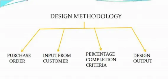
2.What are the inputs required from the customer to start designing a Fixture?
- He must have the following essential inputs: The drawing of the component to be milled – its condition before being presented to the machine and as it comes out of the machine, containing all relevant dimensions, tolerances, surface finish requirements, etc.
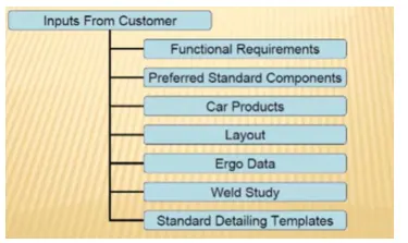
Functional requirements-It is the first input which will define for what purpose the fixture is being mode, whether the fixture is made for welding, hemming, rivetting, inspection etc will be mentioned this is an important fac as based on this input the entire design and development of the fixture is dependent Preferred standard
components- during the development of any project,the team always decidi to involve as much as standard parts as possible as the standard parts are easily and readily available in the market, this will saw the time involved in designing the part, which in turn will reduce the cost of the project ABB, NAAMS, TUNKERS, ZYTRAN, DESTACO etc produce some standard parts which are used in fixture design
Car products-It is the input we receive from the customer, this include the 3d cod model data, GD&T of parts, clamp plan, product assembly process sheets etc these inputs are necessary to begin the project
Layout-Layout gives the information about the flow of parts, robot station, tip dressers, tool changers, platform height, loading and unloading sequence etc layout gives us the understanding of the complete assembly line
Ergo data - Ergo data gives the interaction of the human behaviour during the assembly line it will include data like loading height. safety zone of operator etc.
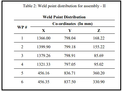
Weld study-this input will show us how the weld gun will be used for the operation it will give us report of weld matrix and the weld point positions this input is necessary as the further development of the fixture will be dependent on this
Standard detailing templates- Every company has their own specific standard template used for 20 drawing and drafting the customer will provide us their templates so that we can incorporate that in our 2d sheets
3.What is the input we get from "Car Products"?
The inputs that we get from the care products are as follows:
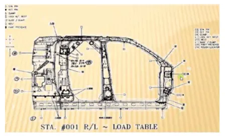
GD&T; Part Lists; CAD Files; Clamp Plan; Product Assembly Process Sheet. GD&T; The input about the geometric dimensioning and tolerance of the part for which the fixture is being designed.
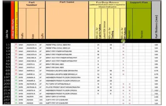
Parts list-Part list will give us detailed information about the parts involved in the fixture, it will give us information like part name, part number, thickness of part, quantity of parts etc
Cad files-Cad files of the part gives us information of 3d model, design analysis result this information is very useful as it will give us an idea on starting to design a fixture
Clamp plan-Clamp plan is very important information as it will give us idea of places where we have our clamps, pins, dumps, rest etc. we should never change the clamp position unless we ask the customer and they agree to it
Product assembly process sheets-in product asssembly process sheet, we will find what kind of products we are going to assemble for the particular unit or the component
The sequence of the assembly will also be given in this sheet
4. What is the Clamp plan?
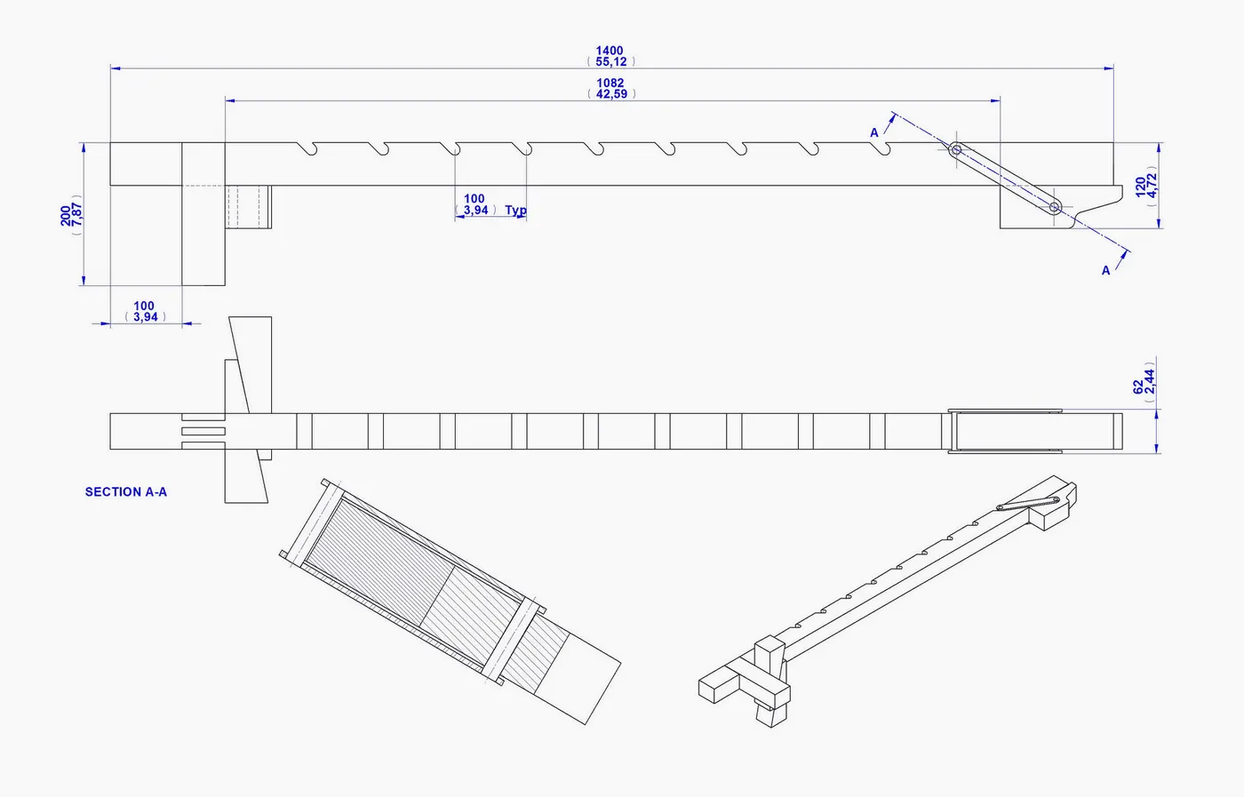
The commonly known 'plan clamp' is also known as a plan binder, plan holder, plan hanger, plan rack or plan drawing hanger. They are available in 4 different sizes ranging from A0, B1, A1 and A2.
Facility Layout Objective
A model facility layout should be able to provide an ideal relationship between raw material, equipment, manpower and final product at minimal cost under safe and comfortable environment. An efficient and effective facility layout can cover following objectives:
- To provide optimum space to organize equipment and facilitate movement of goods and to create safe and comfortable work environment.
- To promote order in production towards a single objective
- To reduce movement of workers, raw material and equipment
- To promote safety of plant as well as its workers
- To facilitate extension or change in the layout to accommodate new product line or technology upgradation
- To increase production capacity of the organization
An organization can achieve the above-mentioned objective by ensuring the following:
- Better training of the workers and supervisors.
- Creating awareness about of health hazard and safety standards
- Optimum utilization of workforce and equipment
- Encouraging empowerment and reducing administrative and other indirect work
Factors affecting Facility Layout
Facility layout designing and implementation is influenced by various factors. These factors vary from industry to industry but influence facility layout. These factors are as follows:
- The design of the facility layout should consider overall objectives set by the organization.
- Optimum space needs to be allocated for process and technology.
- A proper safety measure as to avoid mishaps.
- Overall management policies and future direction of the organization
Design of Facility Layout
Principles which drive design of the facility layout need to take into the consideration objective of facility layout, factors influencing facility layout and constraints of facility layout. These principles are as follows:
- Flexibility: Facility layout should provide flexibility for expansion or modification.
- Space Utilization: Optimum space utilization reduces the time in material and people movement and promotes safety.
- Capital: Capital investment should be minimal when finalizing different models of facility layout.
Design Layout Techniques
There are three techniques of design layout, and they are as follows:
- Two or Three Dimensional Templates: This technique utilizes development of a scaled-down model based on approved drawings.
2.Sequence Analysis: This technique utilizes computer technology in designing the facility layout by sequencing out all activities and then arranging them in circular or in a straight line.
3.Line Balancing: This kind of technique is used for assembly line.
Types of Facility Layout
There are six types of facility layout, and they are as follows:
- Line Layout
- Functional Layout
- Fixed Position Layout
- Cellular Technology Layout
- Combined Layout, and
- Computerized Relative Allocation of Facility Technique
ErgData is a free application designed to run on iOS and Android devices connected to a Concept2 Performance Monitor. Please check the How To Use page for information on connecting your iOS and Android device.
-Ergonomics is the application of psychological and physiological principles to the engineering and design of products, processes and systems the goal of human factor is to reduce human errors, increase productivity and enchance safety and comfort with specific focus on interaction between human and rhing of interest
-In any operation, the workers or operators attain various postures, exerts force and work continously in a cycle time to perform a particular task this may cause high level of strain to the operators to avoid this the principle of ergonomics is applied in every operations wherever a interaction of human with machine is involved so the ergo data is the input which gives human factors engineering data between operator and its working environment It has various benefits like improved working condition, reduce physical workload, improved work postures, reduced efforts of certain movements etc Welding is a process which is widely used in automobile industry for joining of parts together so a
7. WHAT DO YOU UNDERSTAND BY WELD STUDY?
welding fixture is necessary to be made so that the geometry of the part does not change during the welding process weld study includes study of weld gun and the weld matrix and weld points, geo spot and respot weld points
-weld gun study will give information about type of weld, temperature type of current approach points will give us information on exactly where the welding will be done of gun etc weld matrix and the weld
There will be two welding stations, geo spots and repots geo spots will be the first round of welding operation, after this respot is done on the places where we could not weld in the geospot station
8.What are the criteria for percentage completion in the designing stage? Explain it in detail
The percentage of completion method falls in line with IFRS 15, which indicates that revenue from performance obligations recognized over a period of time should be based on the percentage of completion. The method recognizes revenues and expenses in proportion to the completeness of the contracted project.
There are two conditions to use the percentage of completion method:
- Collections by the company must be reasonably assured.
- Costs and project completion must be reasonably estimated.
Journal Entries: Percentage of Completion Method
Journal entries for the percentage of completion method are as follows:
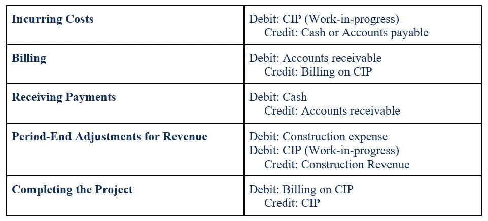
Cost-To-Cost Approach
In the cost-to-cost approach, the percentage of completion is based on the costs incurred to the estimated total cost to complete the project. Therefore, the equation for the cost-to-cost estimate of percentage completion is:
Percentage complete:

Revenue recognized:

9.Brief about "Output" in design?
A design output is a drawing or specification or manufacturing instruction. Design outputs describe all the components, parts, and pieces that go into your medical device. Design outputs describe all assemblies and subassemblies of your product
Input and output design. In any system results of processing are communicated to the users and to other system through outputs. In output design it is determined how the information is to be displaced for immediate need and also the hard copy output. It is the most important and direct source information to the user.
Herein, how do you define essential design outputs?
Verify that the design outputs that are essential for the proper functioning of the device were identified. Design outputs are the work products or deliverables of a design stage. Examples include, diagrams, drawings, specifications and procedures. The outputs from one stage may become inputs to the next stage.
What are the requirements of form design?
Form design requirements
- Each form must have an associated Display Menu Item. The Display Menu Item's Allow Root Navigation property must be set to Yes.
- Each form must be directly accessible via its Display Menu Item.
- Each form that shows data must have one Master Root Data Source.
- Each form must work with the data source filters.
10.What do you understand by structuring a design tree? How does it reduce errors during the design process?
Structuring a design tree is the process of naming all the assembly and parts in a systematic way and a specific standard every customer has its own standard to structure a design tree
-If the parts or the assemblies are not named properly or it is not structured properly, then this will create a lot of confusion to understand the design So structuring a design tree is very important as it helps us to easily identify about the part or a assembly belongs to
which project it can also help us to identify quantity of items of same type or different type used in assembly From the above image we can see that the designed parts are at the top and the standard parts are below
-Blue highlighted number-HIL-T9A-RRFRA-JG3-00-00-00, this is the product description or name -here
HIL-T9A is the project name, RRFRA is the panel name, JG3 is referring to the jig number that is g 3.00 is the unit name 00 is the part number, 00 is the componenet no
11. WHAT ARE UNITS? MENTION 5 TYPES OF UNITS?
ANS-A unit is a device which has a specific purpose and s also a part of a complex assembly the BW fixtures is a assembly of many units,
this units perform different functions units are of two types unitized and non unitized tool
The units have specific function like resting the panel clamping the panel locating the part, etc
4 The 5 types of units are Fixed pin unit-It is the non movable locating unit used for proper location of part and it arrests all the movement of part as well
Retract pin unit-It is a movable locating pin unit which has retracting mechanism, this helps in case of assembly of two components placed in different direction)
Rough locator unit It acts as a rough guide so that the operator can mount the workpiece in proper place Rost
unit-Rest unit makes the panel rest on it Bithithithibhatd Base unit-It is the unit on which all oyber units are mounted
12.Describe Fixed Pin units & their purpose?
-Fixed pin unit is a non movable locating unit used for proper location of part and it arrests all the movement of part as well fixed pin unit consist of pin, pin retainer, shims/spacer, block, blade or adaptor plate riser Riser is the part which is used to rise or increase the height of the unit blades is mounted on the riser block will be mounted on the blade
shims are small spacers which are used for stack up tolerances shims are made of various thickness like 0.1,0.2.0.5mm etc. pin retainer will hold the pin and the pin is used to locate the part and restrict Purpose of fixed pin unit
-The main purpose of the fixed pin unit is to locate the car panel and its motion restrict its motion it is placed following the
3-2-1 principle, so it is necessary to have two pins like pin will restrict 4 dof (4 translational) and the other pin must restrict 2 dof (2 rotational)
13.What are the different parts of a fixed unit?
The different parts of fixed pin are as follows
Pin-Pin or locating pin is used for location or positioning of workpiece in correct manner this pin is mode of precise dimension and tolerance usually two pins are enough to locate a workpiece on a single plane. There are many types of locating pins available it is upto us what kind of pin will work for our workpiece Pin retainer
- A pin retainer is a part which is used to hold the pin firmly and in position a pin retainer can be a make part or a standard part also shims/spacer-Shims and spacers are plate of varying thickness which is used for compensation of stack up tolerance that is in assembly the thickness of shims is 0.1mm, 0.2mm, 0.5mm etc sometimes in an assembly stock up tolerances is generated, this needs to be corrected so we use
shims and spacers: Block-Block can be machined to any thickness, this depends on the design of fixture and for what reason we want the block
Blade-Blades are plates attached to the risers parts like cylinder arm etc are mounted on the blade
Risers - Riser is a standard part which is used to rise up the height of whole unit risers are generally made of plate fabrication or plate and tube welding or from single gas cutting
14.-WHAT IS THE PURPOSE OF MAKING A REST UNIT AND DESCRIBE ITS PARTS?
ANS Rest unit is designed to support the car panel using using myler, NC block It is the most simplest unit as it has only few parts like NC block, spacer/shims, blade riser because of simplicity in design it is combined with other units to reduce the number of parts which will reduce cost it can be combined unit so that it can clamp as well as rest the part, it can be combined with locating unit to locate as well as rest the part the differet parts of the rest unit are
NC block/Mylars it is a part which is used to hold the panel from top and bottom mylars are of resting mylars mylars have a jaw type shape, which improves the holding of part mylars are also two kinds clamping mylars and known as fingers it wont allow the deformation of the part during the welding processes Spacers/
shims Shims and spacers are plate of varying thickness which is used assembly the thickness of shims is 01mm 02mm 0.5mm etc sometimes for compensation of stack up tolerance that is in in an assembly stack up tolerances is generated this needs to be corrected so we use shims and spacers C Blades
-Elades are plates attached to the risers, parts like cylinder arm etc are mounted on the blade Risers
-Riser is a standard part which is used to ne up the height of whole unit risers are generally made of plate fabrication or plate and tube welding or from single gas cutting
15. What are the basic fundamentals to design a Sensor unit?
-A sensor is a device which detects or measures a physical property, and records, indicates or responds to it a unit which is designed to sense a object is called as sensor unit the information from the sensor is send to
the PLC a sensor is sensitive and can be damaged so a sensor cover is provided to it there are different types of sensor like proximity sensor, laser sensor, infrared sensor, photoelectric sensor etc
-Fundamental to design a sensor unit Every single loose panel which is being welded by the tool should be sensed Each panels should be sensed by 1 or 2 sensors depending upon size of panel Every sensor should be mounted in a 3 direction adjustable way in general
16-WHAT IS A ROUGH LOCATOR UNIT AND WHAT IS THE BASIC FUNDAMENTALS CONSIDERED WHILE DESIGNING IT?
ANS-Rough locator is a device which is used to guide the workpiece in proper place this rough locators is mainly used when manual operator is present but it is also used in automation rough locator act as a foolproofing method.
-Fundamentals considered while designing rough locator Rough locator should be placed at edges of car panel, which it has to guide
They should be placed in a same angle of car edge angle, and minimum of 2-5mm distance should be maintained from edge of car panel It should guide the panel in locating pins Rough locator should start guiding the car panel before 10-15mm from start of engagement
Rough locator should be designed with entry ongle for car panel, which The rough locator should be designed with two slots for easy adjustments is generally 30-45 degree.
The slot should be in direction of car part guiding
17.-WHAT IS A BASE UNIT AND DESCRIBE ITS PARTS?
-A base unit is a unit designed to mount all other units (clampunit, rest unit, pin unit etc.) on it it also mounts other tools like pneumatic valve box, trunking cable path etc will be mounted on the base unit. the base unit can be firmly fixed to the ground or it can be a movable unit.
Base unit parts are given below Floor plate Floor plate is used to mount entire base with floor it also helps to achieve the flatness of the fixture Weld bars and pedestal Pedestal is a structure where entire unit of base will be mounted Eye bolt-Eye bolt is the bolt with a loop at one end they are used to firmly attach a securing eye to the structure when the whole faxture table has to be moved from one place to another cables are attached to this bolt and the foxture table is moved Measuring hole cover
The base plate has several holes for mounting of units on it this holes are measured by CMM machine to check if their position is accurate or not a plate is used to cover the hole so that no dust or other particles can damage the hole Valve box and trunking channel
- Valve box supplies air to all the pneumatic cylinders in the assembly a valve box consist of solenoid valve which is used to collect air from pneumatic cylinders to volve box
Base plate A base plate is a heavy plate of large thickness because it cornes weight of the entire assembly it is machined to maintain parallelity and it also has holes drilled on it to mount the units
18.WHAT IS A DUMP UNIT AND WHAT ARE ITS FUNCTIONS?
ANS-Dump unit is a complex unit which is used in places where there is a space constraints or some other constraint when we have some geometrical constraints and we cannot mount clamp unit, rest unit etc unit is used
It consist of dump cylinder to perform operation of clamping and unclamping of car panel Functions of dump unit When there is a particular constraint and we cannot asssemble component in normal way dump unit is used It has a dump cylinder which performs the opening and closing action it has a clamp cylinder unit too
This dump unit is complex in design and so it is used only in need
19-WHAT IS A SLIDE UNIT? MENTION WHERE SLIDE UNITS ARE COMMONLY USED?
-Slide units are positioning unit which are used to position the car part or panel, units, robots, for further operation sliding units are used in places where we have space constraint and differnt units cannot be used so we use sliding unit it consist of foll parts Sliding cylinder- this is used to move
the panel from open position to close position and vice versa Position locking unit-It is used to lock the plate at a particular place and it will not allow it to move Guide rail
-It is used to guide the plate to move from one position to next. Stopper block-It is used to control the motion of sliding unit Sensor unit
-It is used to sense whether the component is moving property or not.....