Week 6 - Creating connection for Rear door
DEPLOYING CONNECTIONS TO AN AUTOMOBILE REARDOOR USING ANSA:-
Aim:-
To determine and deploying suitable connections to an reardoor FE model, by applying different PIDs for different components, with the appropriate techniques and method of connections.
Procedure:-
1. Open the ANSA Software.
2. Click on the downloaded Reardoor FE model and open it.
3. Click on the downloaded Reardoor FE model and open it. After the TOPO cleanup, then we have to check the geometrical errors for further steps of deploying connections.
- Firstly, we have to click on the 'GEOMETRY' in the Checks Manager(Tools>Checks>Geometry), then an Auto generated template will be occured.
- Secondly, after displaying template, likewise we have to click on the 'Execute' option in the template which will dispalyed the status of error visibility.
- Then, after displaying errors, we can 'Auto-fix' this error. Select all the errors and by right clicking 'Fix' option will be generated and by click on it auto-fix error will automatically be resolved one after another. For this, we have to use 'Hybrid Not'(Bullens>Hybrid Not) option.
- Admittedly, these errors should be resolves sequence by sequence, so click on error and go to the option 'show only' then the error will be displayed. Likewise, go to Release(CONS>Release) option, then by clicking on it and doing window selection of TOPO in faces, our error will be resolved respectively.
- Then, when all errors are resolved, then in template it will shown geometry check status as 100% which clarify that our geometrical errors along with TOPOLOGY clean up is up to the mark.
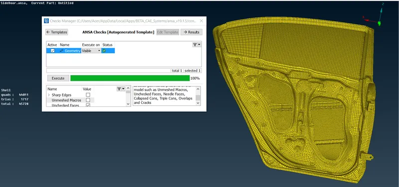
4. Now, we have to 'Set PID'(Mesh>Macros>Set PID) for different components according to the user's requirement. Then, we have to import the file in the NASTRAN deck, where our model can view as a single PID. After that, we go to the next step of deploying connections in the NASTRAN deck.
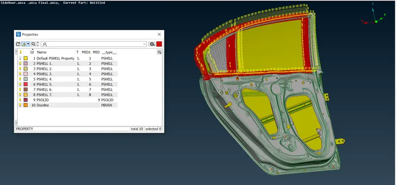
5. Connections:-
- RBE2 Connections:-
- RBE2 Spider Connection:-
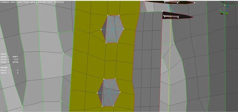
- This is a type of RBE2 connection(Rigid body element) which we provide to one hole which is present on the model to make it rigid on all axes.
- We have to select RBE2(NASTRAN>Elements>RBE2) connection in which there are independent holes in the model, there we have to deploy these connections.
- RBE2 Two node Connection:-
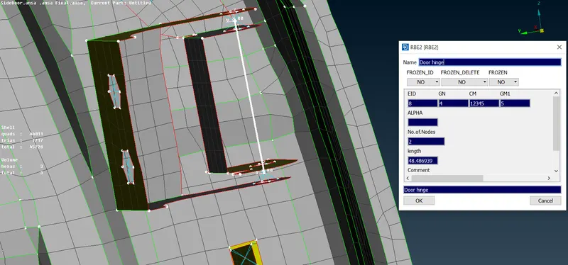
- This is a another type of RBE2 connection(Rigid body element) which we provide connection to the required two nodes to the door hinges of the model.
- We have to select RBE2(NASTRAN>Elements>RBE2>Two nodes) connection in which we have to select two nodes in the model, and then there we have to deploy these two node connection.
- After appying these two nodes connections, we have to select the INFO(NASTRAN>Elements>INFO) tab and open it. After opening the info tab, we have to lock the degree of freedom i.e. CM to only 5th axes, so that the movement of the door can only in the 6th axes.
- RBE2 Single cluster connection:-
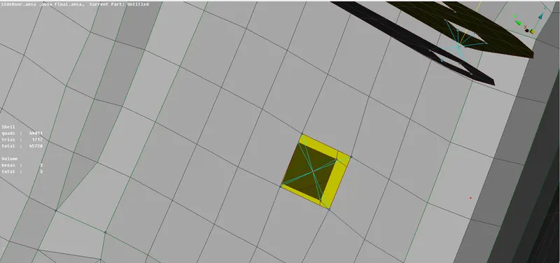
- This is a another type of RBE2 connection(Rigid body element) which we provide connection to the required two or more nodes on two or more sheet metal surfaces which are nearer to each other and lock them in all axes and all degree of freedom, so they can't move in any direction.
- We have to select RBE2(NASTRAN>Elements>RBE2) connection in which wherever there are two more holes near each other in the model, there we have to deploy these connection.
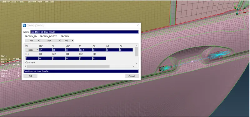
- RBE2 Connections at Door Handle (Concentrated Mass):
- This is a another type of RBE2 connection(Rigid body element) which we provide connection to the door handle by providing the spider connection of two holes at the door handle and then connecting the master nodes of the two spider connections to form a centroid or COG point in the model.
- Then, we have to provide the Con. mass for the COG point using the Nodes(NASTRAN>Elements>Conc. Mass>Nodes) option which we have to applied on the point on the model.
- After that, the tab will generate we have to provide the COG mass as 100 gram, we provide the value of mass in tonnes in Nastran deck i.e. 100 gram=1e-4, and then the conc. mass will be applied on that point.
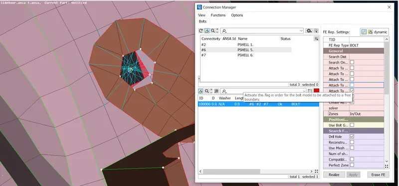
b. Bolt Connections:-
- This is a type of bolt connection, in which we deploy connections where bolts are going to be fitted in the rear door of the model i.e. near to the door hinge of the model.
- In this case, we have to create a COG point(TOPO>Points>On COG) on the one of the surface of sheet metal of the model. Then, we have to convert that 3D point to Bolt washer point(Assembly TAB>Convert>3D Point) and afterwards, we have to open the connection manager tab.
- Next, after opening the Connection manager(Assembly TAB>Connection Manager) tab, we have to select the Bolt point and give the middle mouse click, to which connection manager template will appeared. Then, we have to specify the connectivity which is in format of P1, P2, P3 and we have select it by (Shift+/) button and likewise, we have to select the FE Connectivity type as 'Bolt type' and also the zones as 'In/Out .'
- Lastly, we have to apply and realize it. Then, the bolt connection has been deployed.
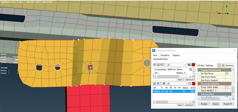
c. Spot Weld Connections:-
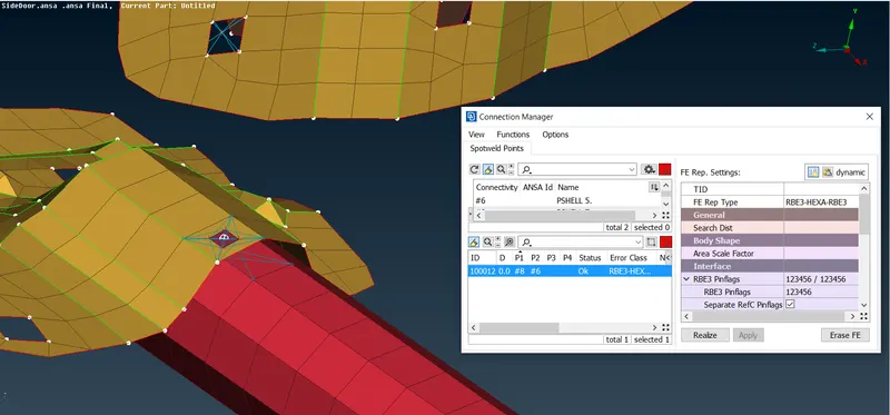
- This is a type of RBE3 connection, where we provide spot welding where we have to attached near surfaces with no filler material in the reardoor FE model.
- In this case, we have to create a COG point(TOPO>Points>On COG) on the one of the surface of sheet metal of the model. Then, we have to convert that 3D point to Spot weld point(Assembly TAB>Convert>3D Point) and afterwards, we have to open the connection manager tab.
- Next, after opening the Connection manager(Assembly TAB>Connection Manager) tab, we have to select the Spot weld point and give the middle mouse click, to which connection manager template will appeared. Then, we have to specify the connectivity which is in format of P1, P2 and we have select it by (Shift+/) button and likewise, we have to select the FE Connectivity type as 'RBE3-HEXA-RBE3', Interface as 'RBE3 Pinflags-12456', Body as we have to create a special 'PSOLID ID' for a spot weld.
- Lastly, we have to apply and realize it. Then, the Spot weld connection has been deployed.
d. CBUSH Connections:-
- This is a type of bush connection which is applied to non-welded component i.e. glass, etc. In this type of connection, we provide connections to the window with the help of bushes so that the window doesn't break during running the simulation.
- In this case, we have to draw curves by using Feat2curves(Mesh>Perimeters>Feat2curves) option towards all the rectangular glass window and then we have to off the FE model. After that we have transform the curve i.e. to copy the curve with option(Transform>Copy) and we have to select the distance as '10mm' and select the 'Y-cordinate.'
- Next, we have to convert that curves to Spot Lines(Assembly TAB>Convert>Curves) one by one and afterwards, we have to open the connection manager tab.
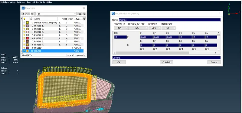
- After that, it will open the Connection manager(Assembly TAB>Connection Manager) tab, we have to select the Spotline point and give the middle mouse click, to which connection manager template will appeared. Then, we have to specify the connectivity which is in format of P1, P2 and we have select it by (Shift+/) button, then we have to define the value for 'S=10.0' and likewise, we have to select the FE Connectivity type as 'RBE3-CBUSH-RBE3', General column 'Search Dist.=50 mm', Interface as 'Keep it all branches should select', and Body as we have to create a special 'PBUSH ID' for a Bush Connection.
- Additionally, we have to define six stiffness values in terms of 'K1, K2, K3, K4, K5, K6' as '0.001, 0.001, 0.001, 10, 10,10.'
- Lastly, we have to apply and realize it. Then, the Bush connection has been deployed.
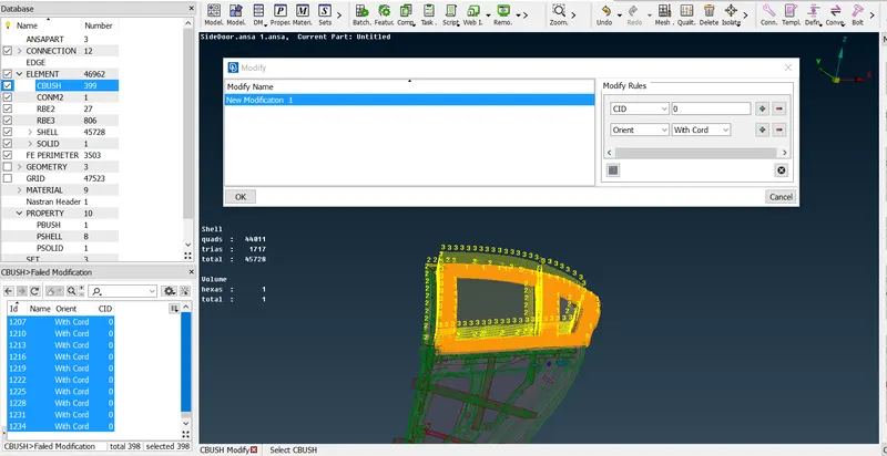
VII. Primarily, the bushes has its own vector coordinate system which is different from global coordinate axes. So, we have to make vector coordinate system as global coordinate system. We have to select the CBUSH elements(Database>Elements>CBUSH) from the tab and after selecting we have to select 'Modify' option and then we have to do new modifications by adding 'Orient-With Cord' and 'CID-0' and click on apply. Then, the vector axes equals to global axes coordinate system.
6. Learning Outcomes:-
- Ability to understand the types of connections perform on different surfaces of the model.
- Learnt the types of welds namely as Spot weld and Seam Weld etc.
- Understand the master and slave nodes, CID (Coordinate system), GM and many more different ID's for one or more elements.
- Understand the connection manager template and FE Representation settings.
- Learnt the conversion of COG point to number of various conversions in 3D points, curves, bolt joint etc.
7. Conclusion:-
In this model, we have finally acheived all the connections for the whole reardoor FE model namely as RBE2 connections, Spot weld connections, Bolt connections, and Bush connections and by resolving all geometrical errors along with a TOPOLOGY cleanup as per mentioned requirement. Atlast, our model has deployed all suitable connections.
Link:-https://drive.google.com/drive/folders/1sBSP9YnolWfZUrHb6tkL7CEVF9VyKzx5?usp=sharing