Week 3 - 2D meshing for Sheet metal
link:
https://drive.google.com/file/d/15CJlUpDN62QYEE-k9P_5UJZXN40Iv5bZ/view?usp=sharing
Aim :For the given Hood model, Take the mid surface for all the components after checking the geometrical errors and mesh the mid surface with the given element Quality criteria. (Refer the table Below for the Quality criteria)
Quailty Criteria Table
|
S.No |
Quality Criteria |
Value |
|
1 |
Target/Average length |
5 |
|
2 |
Minimum Length |
2 |
|
3 |
Maximum Length |
7 |
|
4 |
Aspect |
3 |
|
5 |
Warpage |
15 |
|
6 |
Skewness |
45 |
|
7 |
Jacobian |
0.7 |
|
8 |
Minimum Quad Angle |
45 |
|
9 |
Maximum Quad Angle |
135 |
|
10 |
Minimum Tria Angle |
30 |
|
11 |
Maximum Tria Angle |
120 |
|
10 |
Tria Percentage |
15 |
Procedure:
Opening the cad file in ansa first and then we have to understand the geometry of the hood model and to anaylaze it.Then performing the topo option to join the different part of hood model.After that perform the check geometry there mighty be serval error in the cad file due to format conversion process error should be clear before starting for mid surfaces.after checks geometry we should measure the length of model at different part before performing midsurface.To perform the mid surface there is an option in faces called offset its is used as maunal mid surfacing.After doing mid surfaces the property id should Be created of the midsurfaces.then hide the parent geometry and enable the mid surface property id and then it is ready for the meshing of hood model.Before starting the meshing of the component quality critria should enable for given hood model. The model should not to be fail for given quality parameter.the final step is user should work on better mesh flow for the good finishing of the component by using tool such as Reconstruct,split & swap option.
First step:
- File>open>Select the path of cad file >open
- Perform Topo on hood model>In Module button >face>select topo
Topo :
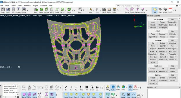
1)Geometry Check:
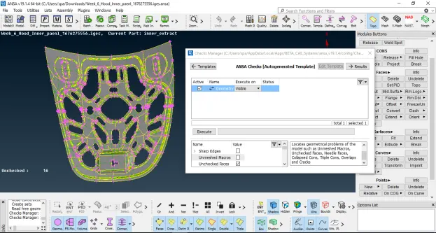
Image geometry checks
Checks >Geometry>single cons enable>Execute button> error will seen>select all right click >fix option
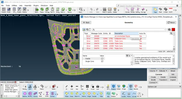
Images of Geometry error
2)Measure a thickness :
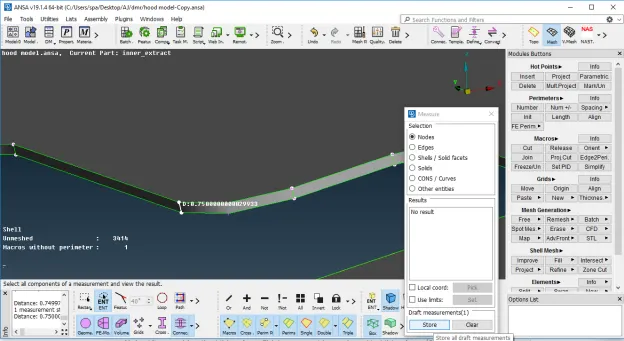
Image of Measurement
- Mid surface :
Modules Button>Faces>offset>select the face of model>middle clk>option list> ask always>enter the value
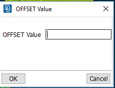
Image of Offset
Property Id :
New>pshell>enter>specify the Name
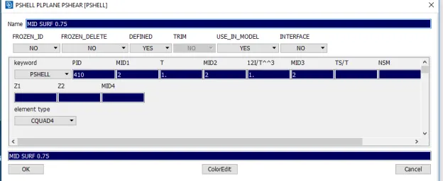
Image of creating property Id
Mid surfaces:
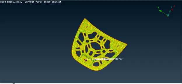
Images of Mid Surfaces
Quality Criteria: Press F11 Enter the parameter

Image of quality Parameter
Target length :
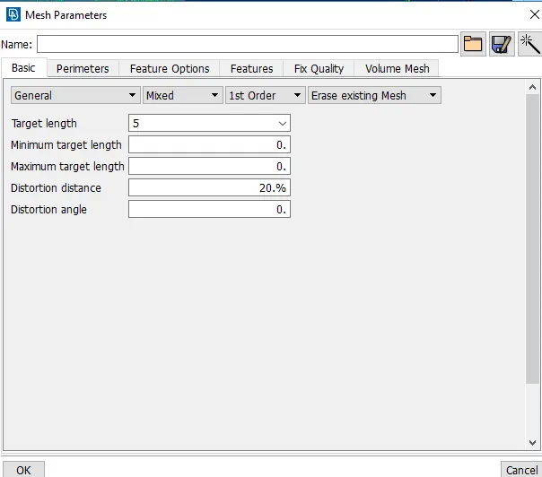
Image of target length
Meshing : Mesh>modules button>perimeter>length>perimeter>marcos
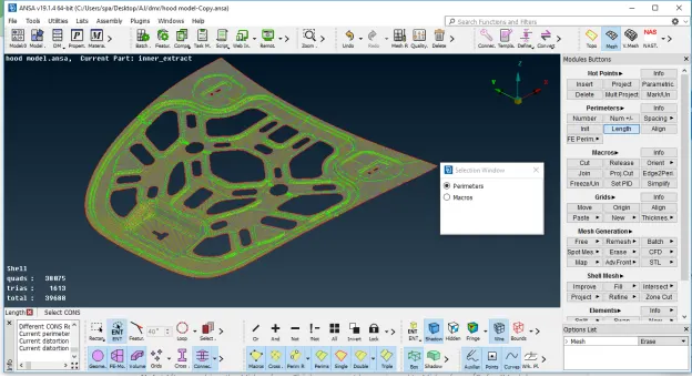
Image of entering value of length
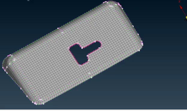
Tool used: Reconstruct , split, swap for eleminating trais
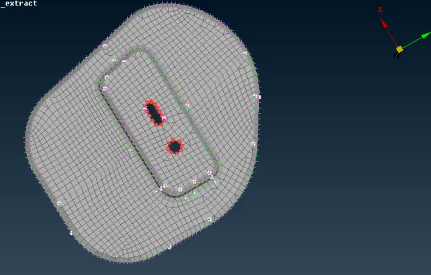
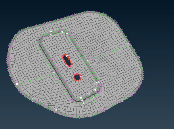
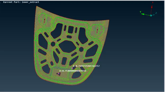
Conclusion : Hence In this project we learn to fix the geometrical error and to take mid surface with given quality criteria and to control mesh flow of the different component.