Week 3 - 2D meshing for sheet metal
AIM
To fix Geometrical Errors and take the mid surface of the 2D elements and mesh them according to the given quality criteria.
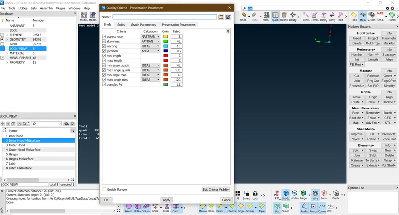
Given Quality Criteria:
|
S.No |
Quality Criteria |
Value |
|
1 |
Target/Average length |
5 |
|
2 |
Minimum Length |
2 |
|
3 |
Maximum Length |
7 |
|
4 |
Aspect |
3 |
|
5 |
Warpage |
15 |
|
6 |
Skewness |
45 |
|
7 |
Jacobian |
0.7 |
|
8 |
Minimum Quad Angle |
45 |
|
9 |
Maximum Quad Angle |
135 |
|
10 |
Minimum Tria Angle |
30 |
|
11 |
Maximum Tria Angle |
120 |
|
10 |
Tria Percentage |
15 |
Procedure
Step1- Import the model into ANSA
Open the file Hood.STP in ansa
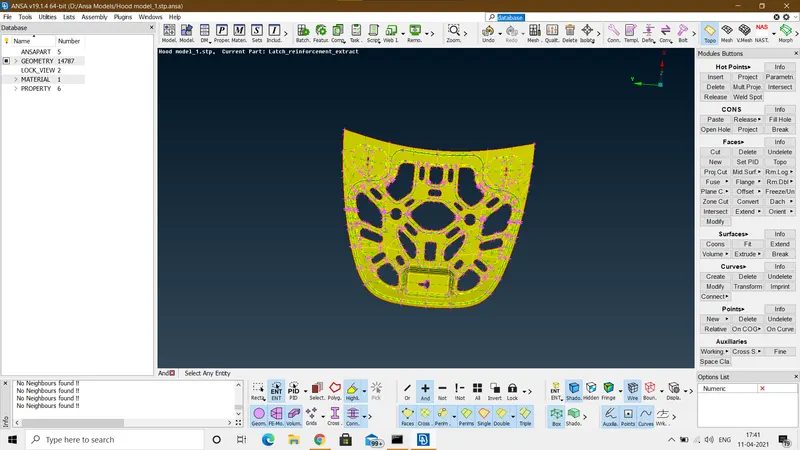
The given model has 4 different parts -
- Upper Hood
- Inner Hood
- Latch
- Hinges
Step 2 - Geometry Cleanup
- In the check manager we select "geometry" and run the check, the geometrical errors then pop up on the screen.
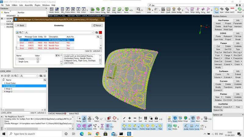
- The errors are removed by deleting needle faces, fixing up single cons, generating new faces where cracks appear and using auto-fix wherever required.
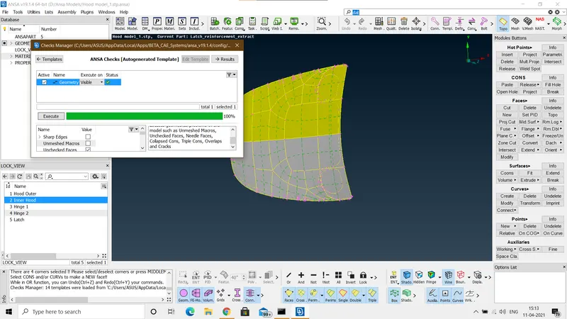
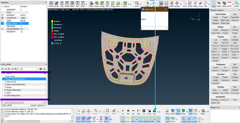
Step 3 - Creating Stored locks for ease of access
Step 4 - Mid Surface Extraction
Method used - Faces - (offset)
- All 4 parts were extracted separately by the faces offset method.
- Under the faces, option choose the offset command :
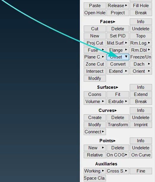
- Select the faces on which you want to apply the offset:
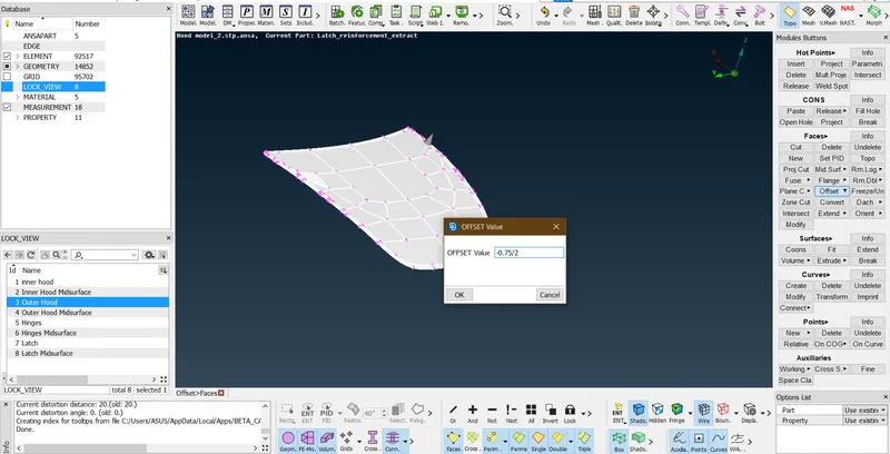
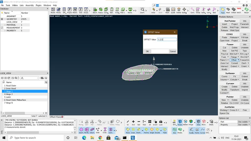
- Enter the thickness value at which you want the mid surface.
- To finalize click the middle mouse button and the mid surface will be created.
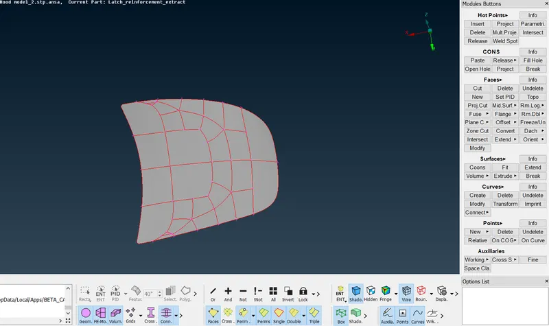
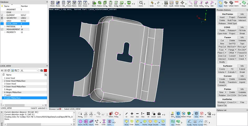
- The mid surface will be shown by red lines and is extracted by using the ! not command.
Mid Surfaces are as shown below :
Outer Hood Midsurface
Inner Hood Midsurface
Hinges Mid Surface
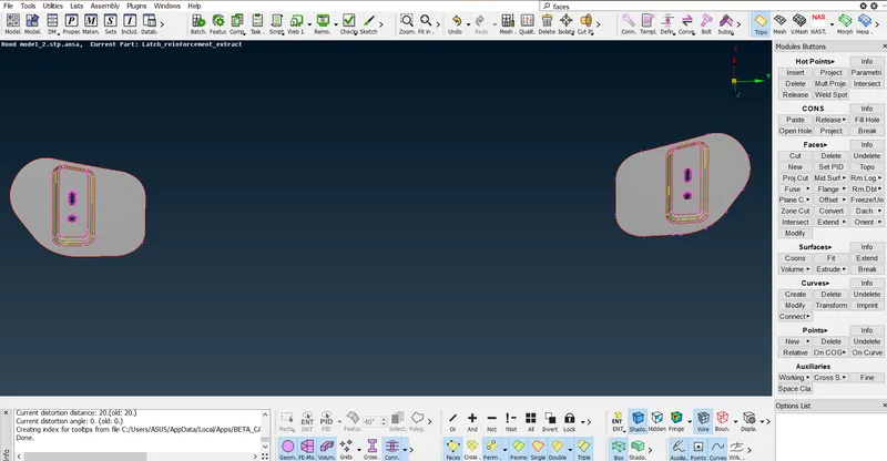
Latch Midsurface
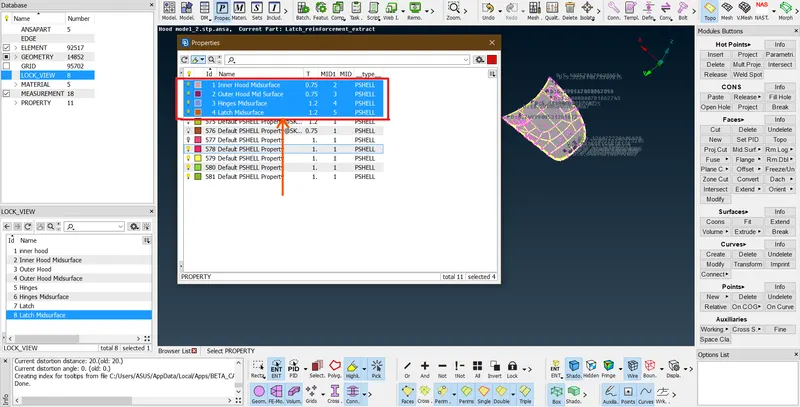
Step 5 - Assigning PID to each part
- To assign new properties, click on the properties tab.
- Right-click and select new "PSHELL", assign the thickness and PID NO. as shown
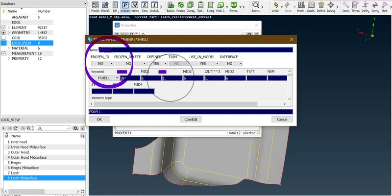
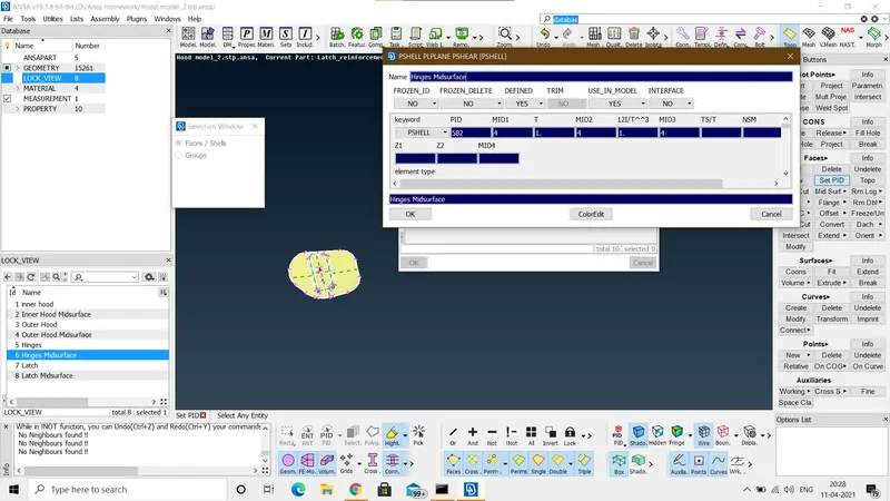
- Assign new PID to each mid surface with the appropriate thickness.
New PIDS assigned to all components as shown below:
Step 6 - Defeaturing
To satisfy the min. and max. length criteria we need to suppress the FE model as per requirements, this is known as defeaturing of the model.
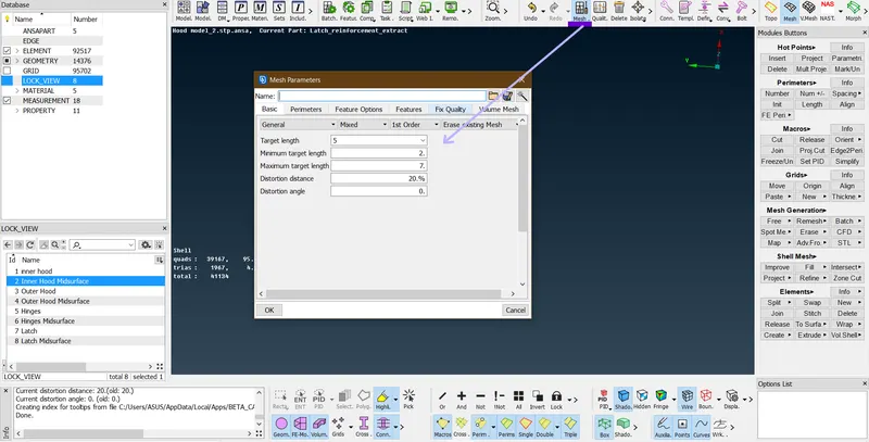
Step 7 - Meshing
- we switch to the meshing mode located at the top right-hand corner.
- Assigning Mesh Parameters - Mesh parameters are assigned in the mesh properties tab as shown below:
- Next, we enter the values of the quality criteria given to us - press F11 or open the quality tab and enter the values as shown :
- Use project cuts to get a good mesh flow.
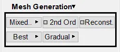
Meshing - under mesh generation tab use the best mesh command as shown below:
Meshing has to be carried out.
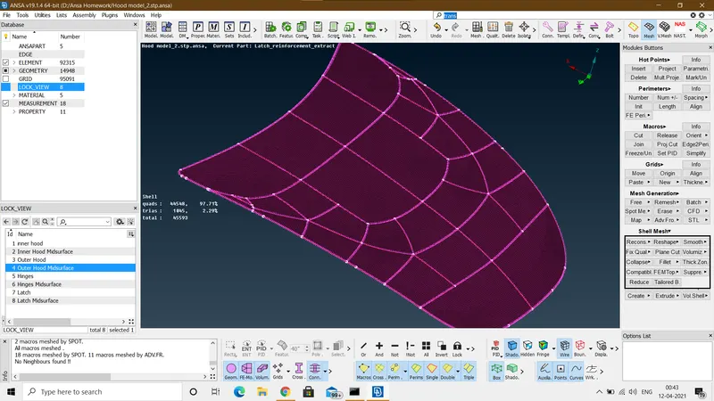
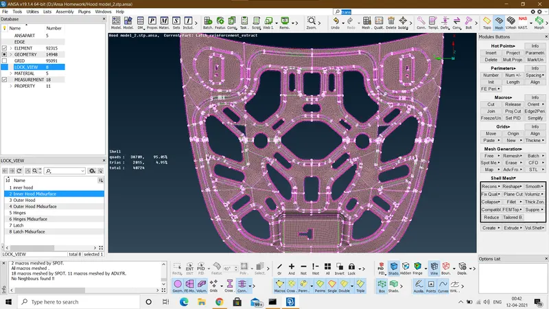
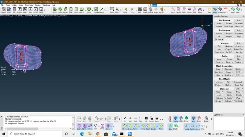
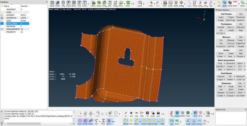
Meshed Model has been shown below separately:
Step 8 - Refining the Mesh
- For refining the mesh we need to get rid of the tria elements near features and have the maximum possible quad elements in the model.
- Commands used- Split, Paste, Swap as shown below :
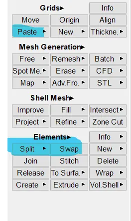
Paste- tria elements can be removed which are facing each other.
Split - used to split tria elements into no of tria or quad elements.
Swap - used to move the trias in a particular direction.
- The mesh is then checked and reconstructed and reshaped wherever required.
The final mesh generation after reduced tria elements and refining the mesh are as shown below:
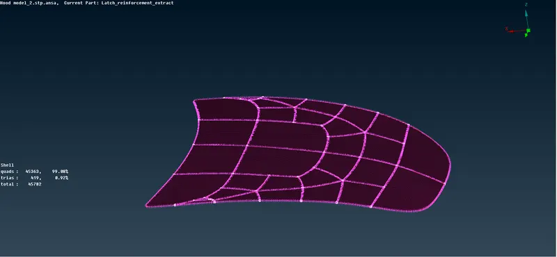
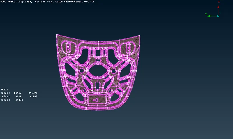
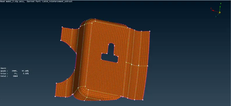
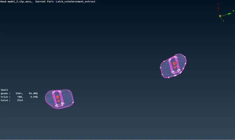
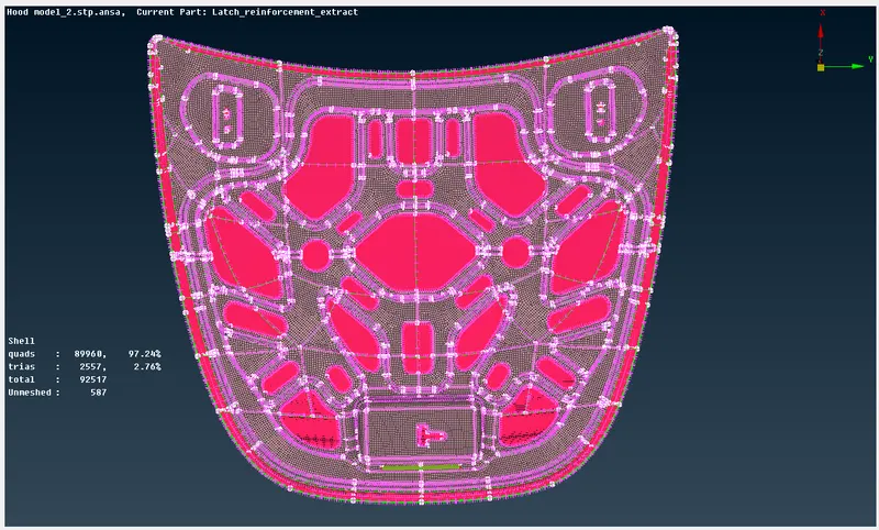
Mid surfaces have been extracted & the given model has successfully meshed.
Learning Outcomes
- Fixing geometric issues such as single cons, cracked surfaces, needle faces etc.
- Taking mid surface by the manual offset method.
- Assigning new PID's to materials.
- Defeaturing Surfaces as per requirements.
- Mesh Generation using best.
- Removal of tria elements.
- Refining the Mesh.
Conclusion
Meshing has been done for given components satisfying the given quality criteria.