Week 3 - 2D meshing for sheet metal
Aim:
1) To check the geometry for the given model.
2) To extract all the mid surfaces of the given component.
3) To mesh all components in the model using the following quality criteria and finally giving thickness to the component.
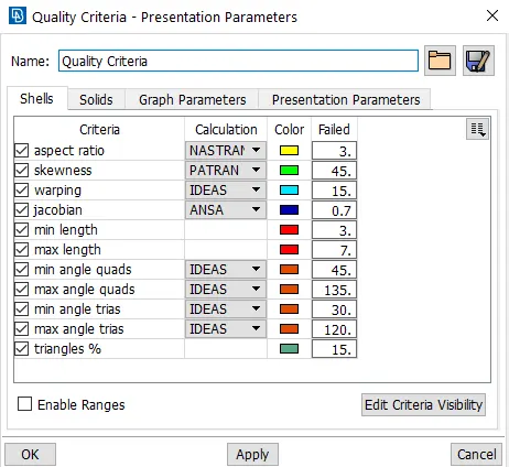
S.No | Quality Criteria | Value |
1 | Target/Average length | 5 |
2 | Minimum Length | 3 |
3 | Maximum Length | 7 |
4 | Aspect | 3 |
5 | Warpage | 15 |
6 | Skewness | 45 |
7 | Jacobian | 0.7 |
8 | Minimum Quad Angle | 45 |
9 | Maximum Quad Angle | 135 |
10 | Minimum Tria Angle | 30 |
11 | Maximum Tria Angle | 120 |
12 | Tria Percentage | 15 |
Procedure:
1. Importing the CAD Model:
1) First, we open ANSA Software and then we import the CAD Model using the File->Open options.
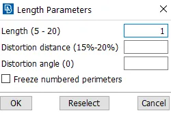
2) After, opening the model we go the mesh module in the modules toolbar and under it we go to the Perimeters section and then we select the Length option. On clicking we can see two options namely the perimeters and macros, we select the perimeter option and select the whole model and click the middle mouse button for confirmation. On confirming it shows a dialog box as shown below. In the dialog the length is typed as 1 because we want a refined model for performing all operations properly and also we do that for good visualization of model.
3) There are different components present in the CAD Model namely Outer Extract, Inner Extract, Latch Reinforcements and Hinge Reinforcements. The images of all components are shown below.
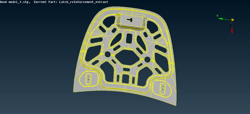
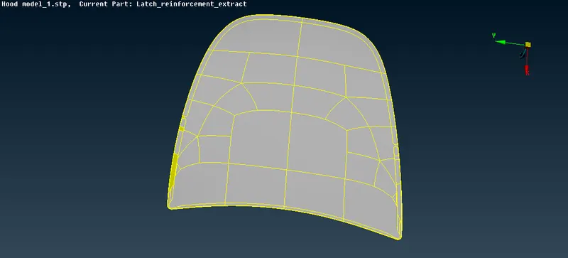
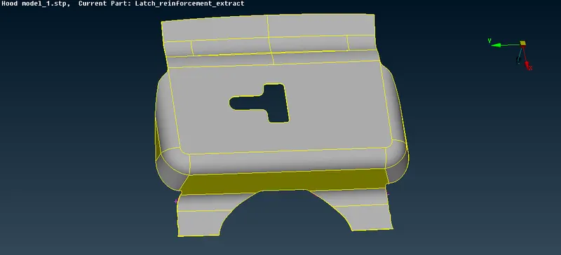
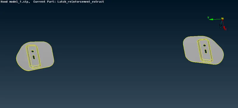
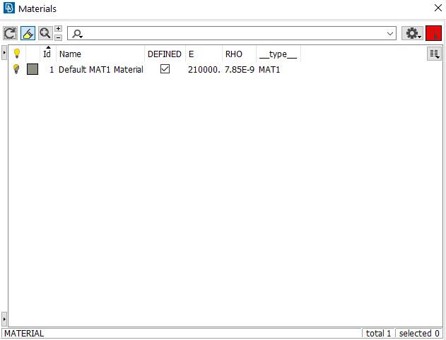
4) We then, perform the Topo operation on the whole model which is present under Faces in the topo module. We then check the material ID and property ID for all components. The material ID should always be defined that is the check box has to be always ticked or else ANSA will not consider the component's material as shown in the image below.
2. Geometry Cleanup:
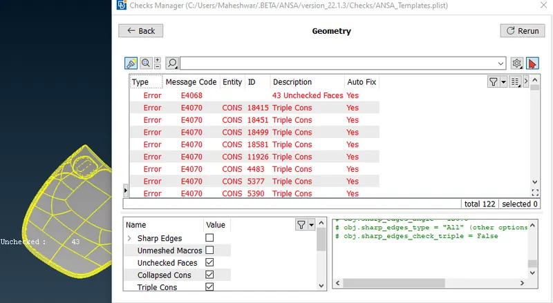
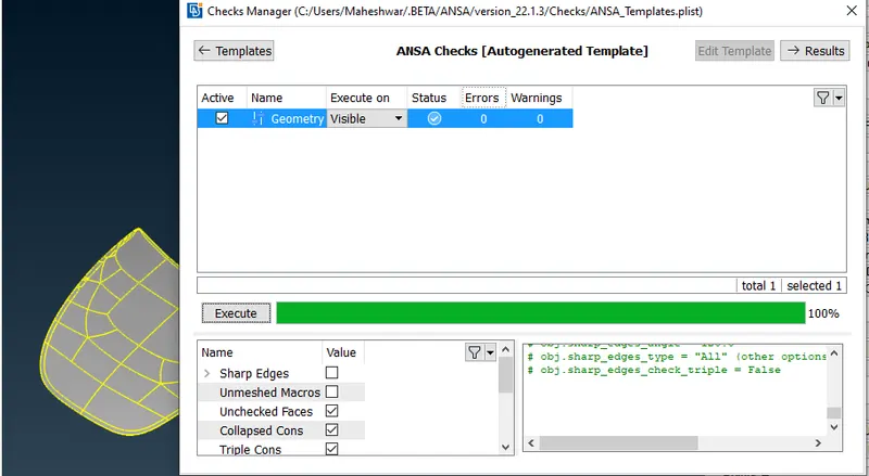
1) After that, we check for any geometrical errors in the model using the Check Geometry which is present under Tools toolbar. Then a dialog box appears in which there are so many options to select including single cons, double cons, triple cons, crack between cones, needle faces etc. and there is an option to execute the check. On executing the check, the are some errors which shown in the dialog box which triple cons, needle faces and unchecked faces as shwon below in the image
3. Mid-Surfacing:
- Outer Extract Mid Surfacing:
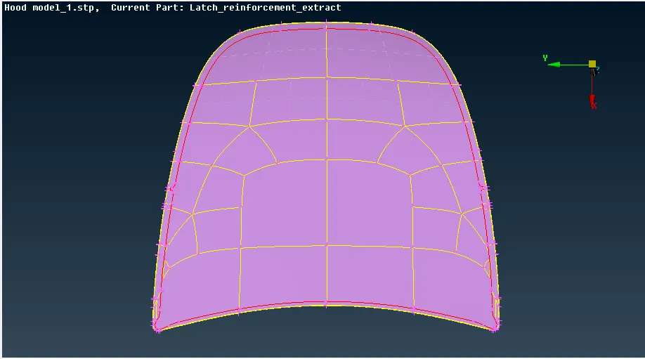
For Outer Extract we perform mid surfacing using the Auto Mid or Mid Surface option present in the Faces section of the Topo Module. We click on the Mid Surface option and then we get a dialog box to select a face. On selecting the face and clicking the middle mouse button for confirmation we automatically get the offset distance and original thickness of the component. On confirming again we get a mid surface that is formed from the parent surface and its property ID gets created automatically. The formed outer extract mid surface is shown in the image given below.
- Inner Extract Mid Surfacing:
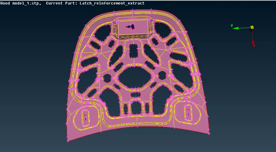
For Inner Extract also we perform mid surfacing using the Auto Mid or Mid Surface option present in the Faces section of the Topo Module. We click on the Mid Surface option and then we get a dialog box to select a face. On selecting the face and clicking the middle mouse button for confirmation we automatically get the offset distance and original thickness of the component. On confirming again we get a mid surface that is formed from the parent surface and its property ID gets created automatically. The formed inner extract mid surface is shown in the image given below.
- Latch and Hinge Reinforcement Mid Surfacing:
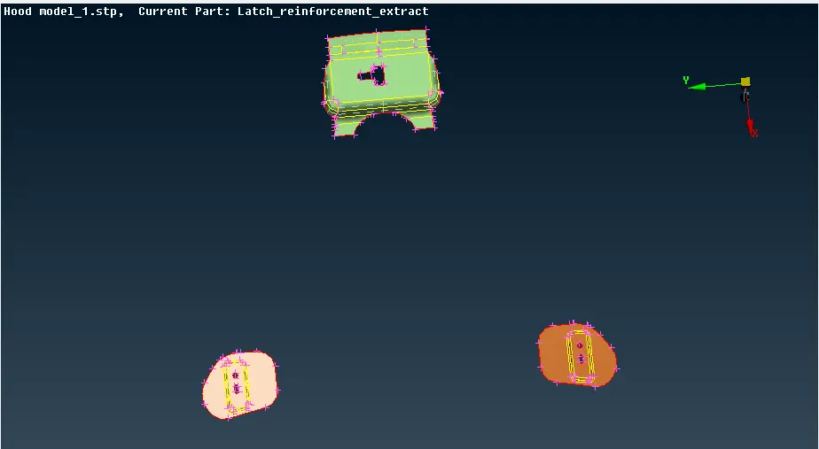
For Latch and Hinge Reinforcement, we perform manual mid surfacing using the Offset option present in the Faces section of the Topo Module. We offset each and every face one by one to get a perfect mid surface. In Offset option we can only select one face at a time and give the offset distance manually. On confirming an offset surface is formed region by region. We can only visualize the mid surface by using the iNOT option present in the Focus toolbar and select the mid surfaces boundry lines one by one and then pressing the middle mouse button to visualize the mid surface. We also have to create property ID manually by going the Lists toolbar and then pressing on the Properties option and then we right click and create a new property -> PSHELL. Finally a midsurface is created and can be visualized properly. The Latch and Hinge Reinforcement's Mid Surfaces are shown in the image given below.
1) We again perform a geometry check before proceeding for the further process but, this time we unselect the single cons check box and execute the check because the mid surfaces formed have no shared surfaces at their boundaries therefore, they are represented by single cons or red lines.
2) We finally store different lock views of the Mid Surfaced components to access wherever in need of it.
4. Meshing:
1) Before, we go to the meshing part we first set the quality criteria given in the aim to get good quality mesh. For this, we first go the Utilites toolbar and click on the Quality Criteria option and then a dialog box opens as shown in the image given below. The required parameters are set and under the presentation parameters in the same dialog box the elements % check box is ticked and the details on demand effect is given as all details.
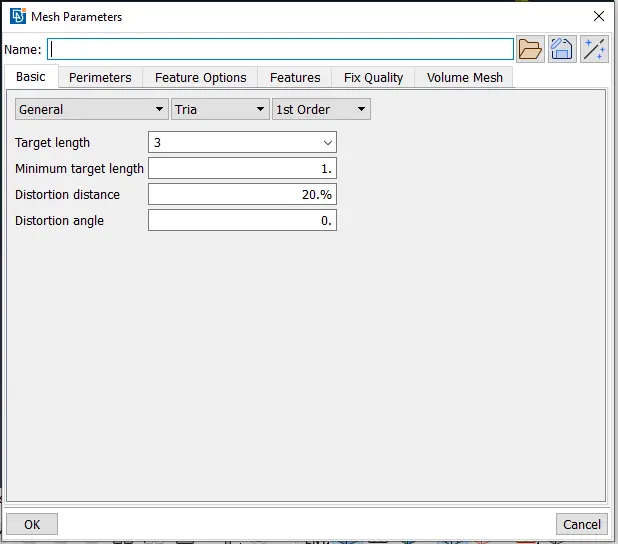
2) We then specify the average or target element length and min length & max length of the mesh using the Mesh Parameters option in the Utilites toolbar as shown in the image given below.
3) In the 2-D meshing we will be considering the above mid surfaced parts and we will be meshing it with mixed elements that include both quad and tria elements according the quality criteria given in the aim.
3)Finally, we proceed to meshing by clicking on the Mesh Module in the Modules toolbar.
- Outer Extract Meshing:
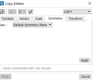
In outer extract, first we delete the unecessary contruction lines and hot points using the Delete option in the Hot points section and using the Cut option in the Macros section. We then make the cut proper for good mesh flow i.e. having almost all elements as quad and less tria elements in the mesh. We also keep checking the measurements of all the fillet and closely contructed regoins and eliminate the unwanted lines so as to obtain good mesh flow. We delete on half of the component using the Rm.dbl option in the Faces section because its a symmetrical component so that we copy the geometry and the mesh together. We then, mesh the component using the Best Mesh option in the Mesh Generation section. On forming the mesh we try to reconstruct and smooth the mesh using the Reconstruct and the Smooth options in the Shell Mesh section. We also use the Split and Swap options in the Elements section to eliminate tria elements. We then, after the meshing process is complete use the Transform option in the Utilites toolbar to copy the meshed component with the geometry as shown in the image given below. On confirming we get symmetrical mirrored part of the component and same mesh is formed on the other side as shown in the image given below.
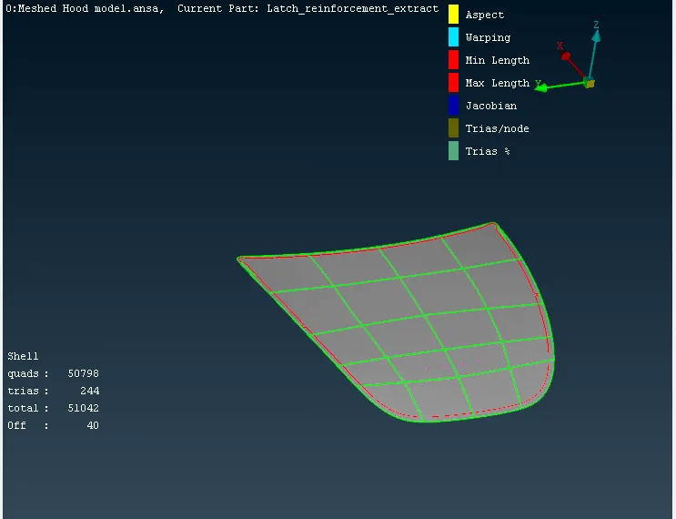
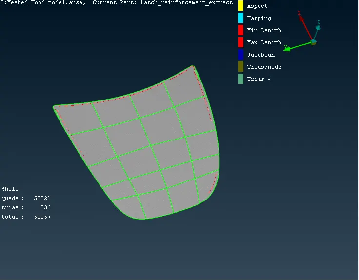
There are off elements formed in the hemming bend and these are formed because of failing in the min length quality criteria and these couldn't be eliminated because of bend and construction lines are important, if we delete the construction lines the bend feature will be removed which is not advisible. These failed elements are seen in red lines as shown in the image below.
- Inner Extract Meshing:
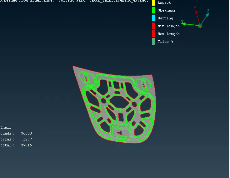
In inner extract, first we delete the unecessary contruction lines and hot points using the Delete option in the Hot points section and using the Cut option in the Macros section. We then make the cut proper for good mesh flow i.e. having almost all elements as quad and less tria elements in the mesh. We also keep checking the measurements of all the fillet and closely contructed regoins and eliminate the unwanted lines so as to obtain good mesh flow. We delete on half of the component using the Rm.dbl option in the Faces section because its a symmetrical component so that we copy the geometry and the mesh together. We then, mesh the component using the Best Mesh option in the Mesh Generation section. On forming the mesh we try to reconstruct and smooth the mesh using the Reconstruct and the Smooth options in the Shell Mesh section. We also use the Split and Swap options in the Elements section to eliminate tria elements. We use the same process of the transforming the symmetric part of the components. The component is shown in the image given below.
- Latch and Hinge Reinforcement Meshing:
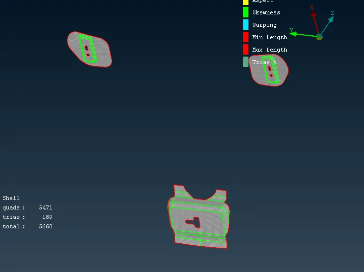
In the Latch and Hinge Reinforcement region, also first we delete the unecessary contruction lines and hot points using the Delete option in the Hot points section and using the Cut option in the Macros section. We then make the cut proper for good mesh flow i.e. having almost all elements as quad and less tria elements in the mesh. We also keep checking the measurements of all the fillet and closely contructed regoins and eliminate the unwanted lines so as to obtain good mesh flow. We then, mesh the component using the Best Mesh option in the Mesh Generation section. On forming the mesh we try to reconstruct and smooth the mesh using the Reconstruct and the Smooth options in the Shell Mesh section. We also use the Split and Swap options in the Elements section to eliminate tria elements. The component is shown in the image given below.
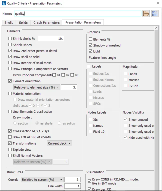
5) Finally we have to give the thickness to the meshed component therefore, we go to the Utilites toolbar and click on the Quality Criteria option and then a dialog box opens as shown in the image given below. In that the Presentation Parameters is clicked and the draw shell as solid check box is ticked.
Conclusion:
The given hood model was checked for geometry errors and mid surface was generated by using both manual and auto mid options. The component was meshed .Finally, the model was assigned a thickness using draw shell as solid in the quality parameter dialog box.