Week 3 - 2D meshing for sheet metal
Week - 3
For the given Hood model, Take the mid surface for all the components after checking the geometrical errors and mesh the mid surface with the given element Quality criteria. (Refer the table Below for the Quality criteria)
|
S.No |
Quality Criteria |
Value |
|
1 |
Target/Average length |
5 |
|
2 |
Minimum Length |
2 |
|
3 |
Maximum Length |
7 |
|
4 |
Aspect |
3 |
|
5 |
Warpage |
15 |
|
6 |
Skewness |
45 |
|
7 |
Jacobian |
0.7 |
|
8 |
Minimum Quad Angle |
45 |
|
9 |
Maximum Quad Angle |
135 |
|
10 |
Minimum Tria Angle |
30 |
|
11 |
Maximum Tria Angle |
120 |
|
10 |
Tria Percentage |
15 |
Procedure
The hood model was imported into ANSA. The hood model consists of five 3D model namely outer panel, inner panel, latch and hinge
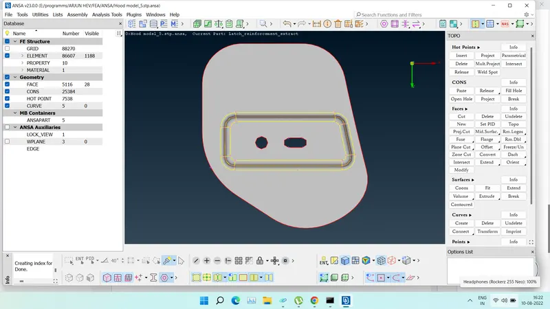
Fig- Hinge
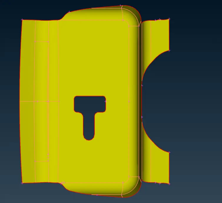
Fig- Latch
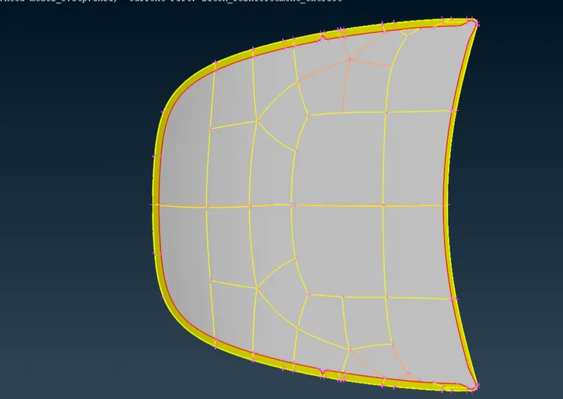
Fig- Outer
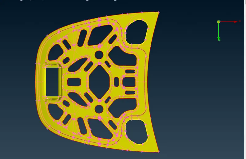
Fig- Inner Part
Once the model is imported the model, there might be error this is mainly due to the conversion of format and it is necessary to clear all these error before getting in to mesh. To clean up geometry first ensure that all faces are connected correctly by face- topo tool and next geometry is checked by the check-geometry tool. The error arise were fixed by error- fix options. Next the faces are oriented by using face=orient tool. Next extract the surface using mid surface tool and keep them separately with PID.
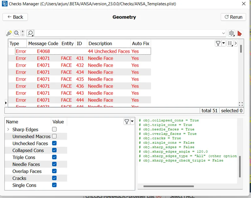
Fig- Errors
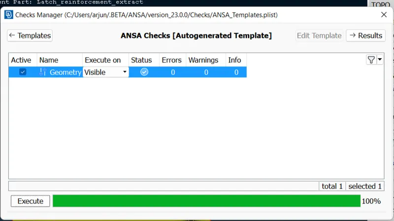
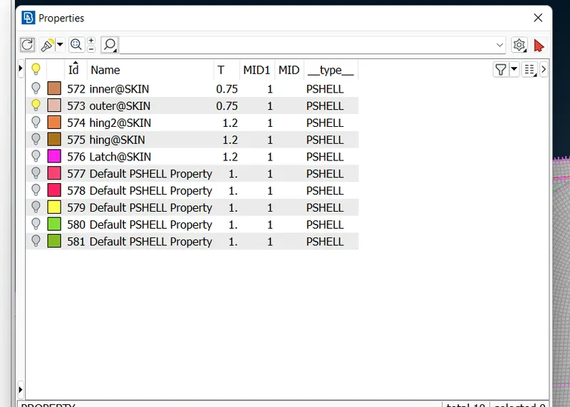
As the outer panel and inner panel are symmetrical in nature only half mid surface is extracted. On other hand, both the hinges are mirror image so one hinge was extracted and latch was extracted using mid surface tool.
- Midsurface -Auto Midsurface – Automatically extracts midsurfaces from surfaces that enclose. a volume or a solid geometry. Can sometimes work if there are missing surfaces. The greater number of missing surfaces, the less reliable the result. Surface Pair – creates a midsurface between 2 selected surfaces.
- Click the ANSYS Workbench button in the ribbon bar to send the current model in SpaceClaim to a new project in Workbench. Everything that is visible in the Design window. ...
- Go to Workbench and click on one of the midsurfaces under Geometry in the project:
- Look in the Properties panel. ...
- Generate a mesh:
Next the mesh parameter are configured using mesh parameters and quality criteria command as shown in Figure
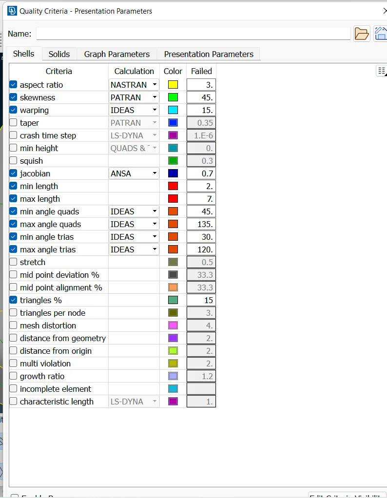
Initially for meshing the perimeters and macros was alerted to 5 and checked for minimum element length and altered where the element failed. The unwanted cons are removed from the surface using join, cut and project cut tool this help to produce the better-quality mesh and slide tool is used to shift the cons ensuring that opposite features are parallel to each other.
Next the meshing process is carried out using best meshing tool which provide the best algorithm for meshing. After that the created mesh is refined using
Mesh-reconstruct
Grid-paste
Elements- swap
Elements-join
Element- split
There are a few ways to handle the mesh flow:
The Tria elements should never be opposite to each other
No Tria elements should be connected back to back
No Tria elements should be on the edge of the geometry
No Tria elements should be near the holes
No Tria elements should be on the feature and the fillets.
There should be less Tria concentration, i.e., there should be a considerable distance between Tria elements.
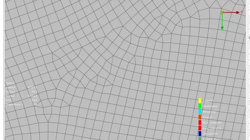
Fig- Distorted mesh
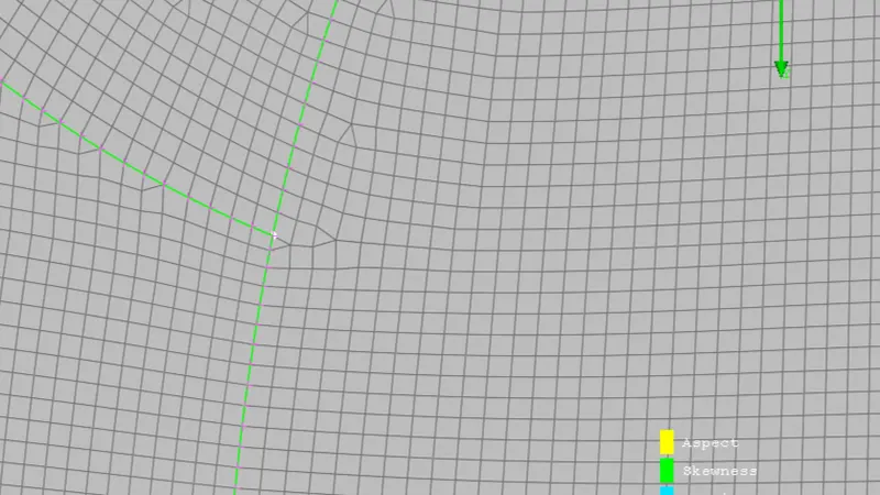
Fig- proper mesh
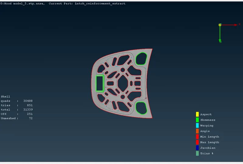
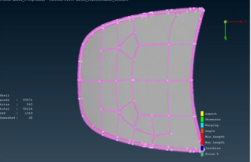
After modifying the mesh, shell mesh – smooth is used for smoothening the flow of mesh. The element failing for quality criteria can be fixed using the remeshing or smoothing the elements. After creating the mesh using the utilities – transform- copy command is used for mirror the object. After that the mirror object was thicken using the draw shell as solid command in parameter. The meshed figure are shown below.
- Results
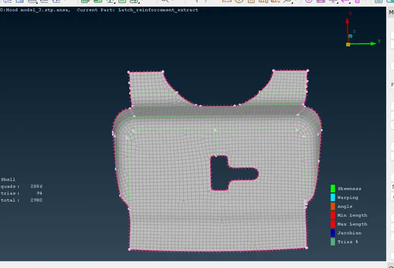
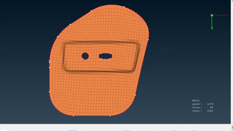
Conclusions
Geometry clean up, mid surface extraction and 2D meshing of the given hood model were made using ANSA tool. All produced element pass quality criteria. All the produced feature have good quality mesh. Tria element was considerably reduced.