2D meshing for sheet metal (Hood Model) using ANSA
ANSA – Hood Model Geometry Clean Up, Midsurface Creation, PID Assignment, and Mesh Generation
- AIM: Using ANSA preprocessor software, for a given Hood model (Outer panel, Inner panel, Latch, and Hinge) check and perform geometrical cleanup, create the mid surface of all the components, also assign property ID (PID), along with the thickness of individual component generate mesh elements with given quality criteria and parameters (refer Table 1),
|
S. No |
Quality Criteria |
Value |
|
1 |
Target/Average length |
5 |
|
2 |
Minimum Length |
2 |
|
3 |
Maximum Length |
7 |
|
4 |
Aspect |
3 |
|
5 |
Warpage |
15 |
|
6 |
Skewness |
45 |
|
7 |
Jacobian |
0.7 |
|
8 |
Minimum Quad Angle |
45 |
|
9 |
Maximum Quad Angle |
135 |
|
10 |
Minimum Tria Angle |
30 |
|
11 |
Maximum Tria Angle |
120 |
|
10 |
Tria Percentage |
15 |
|
Table 1: Mesh Quality Criteria and Parameters |
||
- PROCEDURE:
1. Import CAD geometry: In ANSA preprocessor software import from any of these formats (. IGES, .STL, .STEP, .VDA, .ANSA, CATIA V5, CATIA V6)
- In Title bar -> File -> Open or ctrl + O.
- Select the CAD geometry file and press open.
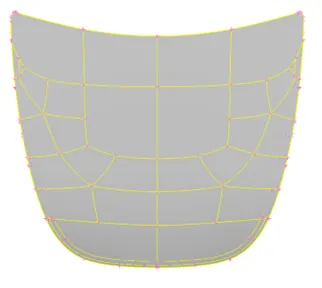
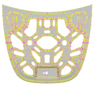
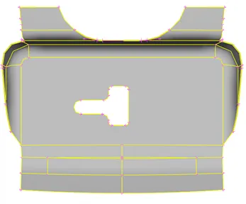
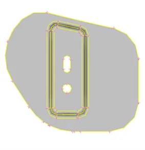
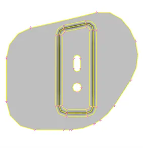
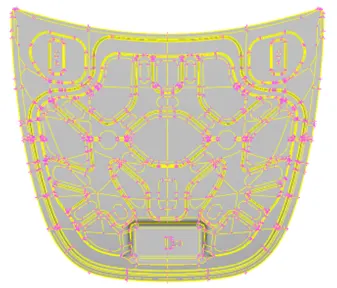
Given below are the pictures of the CAD geometry imported model in ANSA GUI (refer to Fig. 1,2,3,4.1,4.2).
 |
 |
|
Fig 1: Outer Panel |
Fig 2: Inner Panel |
 |
 |
|
Fig 3: Latch |
Fig 4.1: Hinge (Left and Right) |
 |
 |
|
Fig 4.2: Hinge (Right) |
Fig 5: Overall View of Hood Model |
2. Geometry Check and Clean-up: To check whether the geometry has been imported properly with all the features such as edges, faces, etc., and to identify any deleted or duplicate features it is important to perform a geometry check.
- In Menubar -> Tools -> Checks -> Geometry
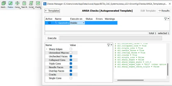
- Check the mentioned boxes in the check manager (refer to Fig. 6).
- Select Execute
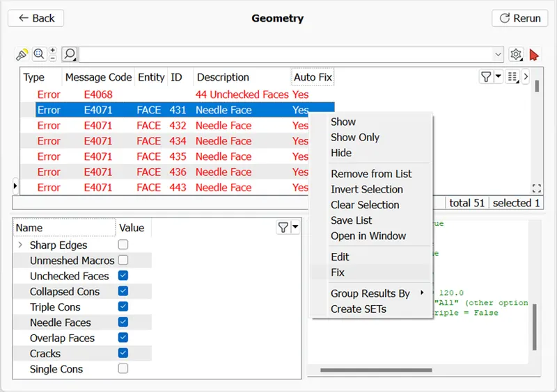
- Errors will be displayed in the check manager; errors can be resolved manually by fixing the geometry with the Topo module or they can be fixed by the auto-fix option provided by the software. (Some errors can be only resolved manually)
- To perform auto fix error, right-click on the error -> select Fix (refer to Fig. 7).
- To resolve errors manually, right-click on the error -> select Show Only (refer to Fig. 7).
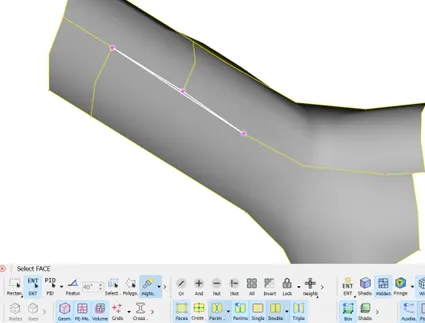
- Bring neighbor entities into visibility, in Faces Draw -> AND, rectangular select the nearby region of error entity (refer to Fig. 8).
 |
|
Fig 6: Checks Manager |
 |
|
Fig 7: Resolving Geometrical Errors |
 |
|
Fig 8: Geometry Error |
- Errors can be resolved using the Topo Module, in Menubar -> Module -> Topo, by using the different options available in the Topo module the errors should be resolved for the entire geometry until there are no errors in geometry available. To check errors again select Rerun in checks manager (refer to Fig. 9).
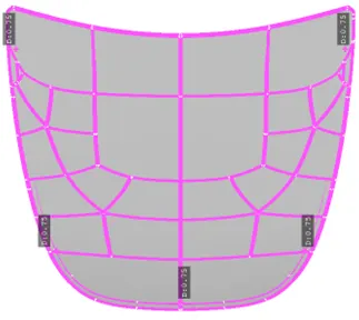
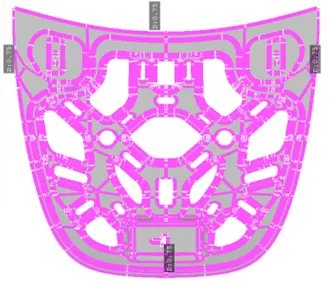
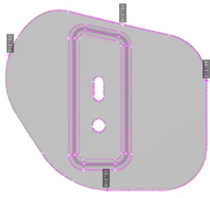
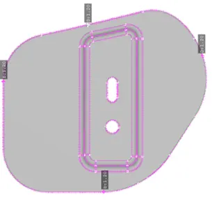
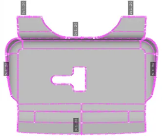
3. Measuring Thickness: The thickness is measured for each component as it varies with different components to verify whether the dimension is varying or constant across the thickness of the surface. This step is important before proceeding to the mid surface. The components can be hidden to work on individual components, In Lists -> Properties or ctrl P.
- In Menubar -> Utilities -> Measure, select two cons or hot points on the surface to measure the distance or thickness of the component. The thickness in the Hood model varies across the component, the different thickness has been mentioned below (refer to Table 2) (refer to Fig. 10).
|
Component |
Thickness (mm) |
|
Outer Panel |
0.75 |
|
Inner Panel |
0.75 |
|
Latch |
1.20 |
|
Hinge Left |
1.20 |
|
Hinge Right |
1.20 |
|
Table 2: Thickness of Hood model components |
|
|
|
|
Fig 10: Thickness of individual Hood model components |
4. Creating Midsurface and Assigning Property ID: The mid surface is created for individual components one by one by hiding the remaining components in the model, the components can be hidden and can be worked on individually. In Lists -> Properties or ctrl P, click on the bulb to show/hide.
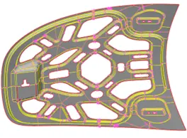
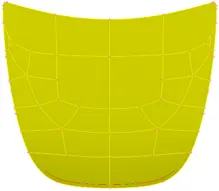
To create a mid surface, there are two options – Midsurface and Offset, the property can also be assigned while creating a mid surface or after the creation of a mid surface (refer to Fig. 11).
- In Module -> Topo -> Faces -> Midsurface -> Skin, this is a direct one-step process to create mid surface for the whole component. After selecting a component, the software will differentiate the component faces in red, blue, and green. Red indicates the top face, blue indicates the thickness face of the component, and green indicates the bottom face. The color indication can be changed if the software doesn’t recognize the face correctly. The software will automatically create the mid surface considering the thickness (this option will also give an edit option to change the offset thickness before confirming the mid surface).
- This option might delete the parent geometry of the components, to avoid that uncheck the delete original faces in the options list of Midsurface.
- In the Midsurface -> Skin option list, the property of the component is set to auto-create.
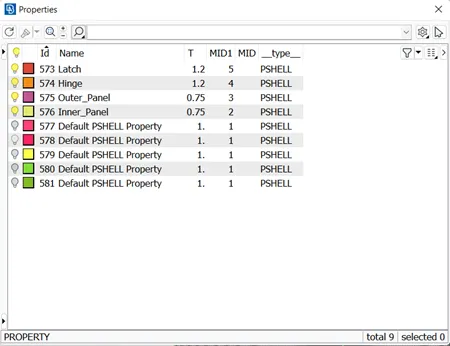
- Open properties (Ctrl + P) and select the newly generated mid surface to rename and assign thickness under T value mention thickness of the component and press OK.
- In Module -> Topo -> Faces -> Offset -> Faces, in this step mid surface is created individually for the faces selected, according to the component, providing the thickness offset (half of the thickness dimension) and checking for the direction of the offset given by the software. The direction of the offset can be changed by the -ve sign before the offset value.
- Before the mid surface is created, the software will ask permission to delete the parent geometry, and press No to keep the parent geometry.
- In the Offset -> Faces option list, change the property of the component to auto-create.
- Open properties (Ctrl + P) and select the newly generated mid surface to rename and assign thickness under T value mention thickness of the component and press OK.
- In Module -> Topo -> Faces -> Set PID, property ID can also be assigned after the mid-surface creation in case of component is not assigned property while creating mid-surface. Select Set PID select the component, in properties list right click and create new PSHELL, under T value mention thickness of the component and press OK.
- The property Id allocation to the component can be verified visually, In Auxiliaries -> Draw Mode -> PID
|
|
|
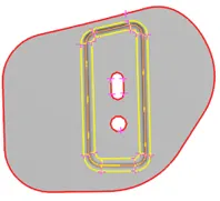
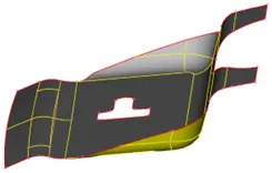
Fig 11: Midsurface of Hood Model Components |
|
|
|
Fig 12: Properties Of Hood model |
5. Setting Up Quality Criteria and Parameters: The quality criteria and mesh parameters are set up before generating mesh to evaluate the mesh quality.
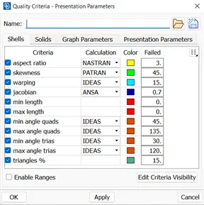
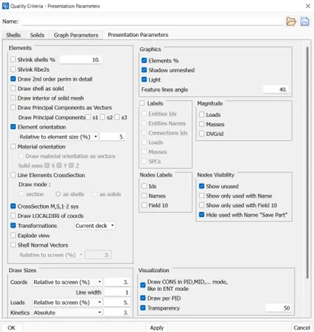
- In Menubar -> Utilities -> Quality Criteria, select the checkboxes and for required criteria give value (refer to Table 1), in presentation parameters, check the box for Element % and set details on demand for more details (refer to Fig. 13). The quality criteria can be saved in the folder, since it is required to set parameter every time software reopens.
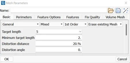
- In Menubar -> Utilities -> Mesh Parameters, set the Target Length and Minimum Target Length as per the required mesh parameters (refer to Table 1) (refer Fig. 14). The mesh parameters can be saved in the folder for later use.
|
|
|
Fig 13: Quality Criteria |
 |
|
Fig 14: Mesh Parameters |
6. Symmetry Check: Before generating the mesh, it is important to check the components' symmetricity
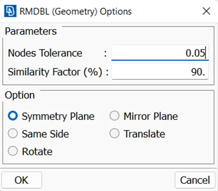
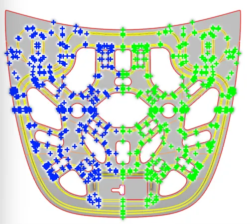
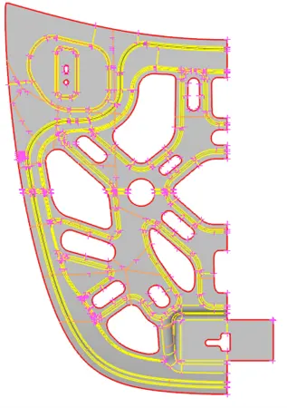
- To check symmetry, In Modules -> Topo -> Faces -> Rm.Dbl -> Geometry, (refer Fig. 15) , In the Hood model Outer Panel, Inner Panel (except Latch area) ,Hinge are symmetrical in the model.
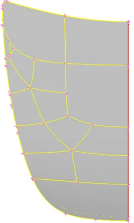
- The mid-surface component can be divided into half using the symmetry plane and can be deleted into half, after meshing the half can be copied using the Transform option, this will reduce time and make mesh flow better.
- In Menubar -> Utilities -> Delete, select half side entities, and confirm delete. This operation can be performed on all the symmetrical components (refer to Fig. 16)
  |
|
Fig 15: Symmetry Check |
  |
|
Fig 16: Symmetrical Components |
7. Generating Mesh Elements: The mesh is generated on each component individually, the constructed lines on the component are suppressed, and if needed it can be recreated
- In Menubar -> Modules -> Topo -> Faces -> Cut, with right-click select, the line will get suppressed, and with the left click select the line can be created between the nodes and cons. This will better the flow of mesh after generation.
- The cons which have less distance between them, and fail minimum element length criteria the cons can be defeatured. In this Hood model, the outer panel component has cons in fillet which needs to be defeatured/suppressed to avoid element failure.
- To generate mesh, In Menubar -> Modules -> Classic Mesh -> Mesh Generation -> Best/Spot Mesh. Select the area of the geometry to get the mesh.
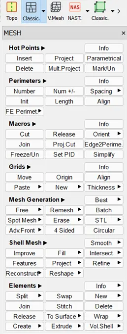
- The mesh generated can be edited by different options available in the Classic mesh tab some important options are Shell Mesh –Reconstruct, Reshape, Improve; Elements-Split, Swap, Join; Grids- Move, Origin, Paste (refer to Fig. 17)
 |
|
Fig 17: Classic Mesh Option |
- The mesh generated should be edited till the model achieves:
- the better mesh flows.
- minimum Trias obtained.
- Trias at fillet, edges, and holes is removed
- back-to-back opposite Trias are removed.
- Rotational quads are removed.
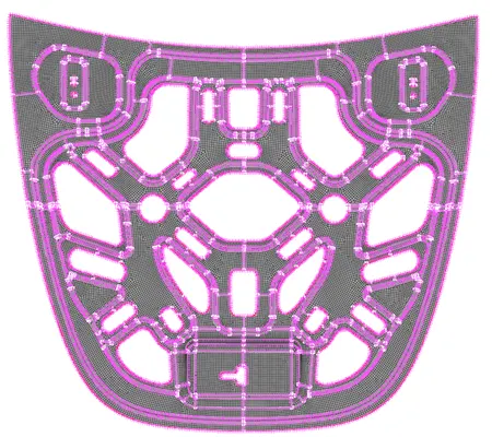
- After the generation of mesh, the half-meshed model can be copied to make another half of the model.
- In Menubar -> Utilities -> Transform -> Copy -> Symmetry, press ok (refer to Fig. 18).
- In the last step, we can visualize the thickness of mesh elements, In Menubar -> Utilities -> Quality Criteria -> Presentation Parameters, check the box for Draw shell as solid.
- In the last step, after confirming the mesh parameters, quality, and property ID, the model can be proceeded with releasing of mesh from all the Hood model components. In Menubar -> Modules -> Classic Mesh -> Elements -> Release, select the component and press Ok. Now the model is ready for the next steps such as boundary conditions and further FEA process.
|
|
|
Fig 18: Hood model components after meshing |
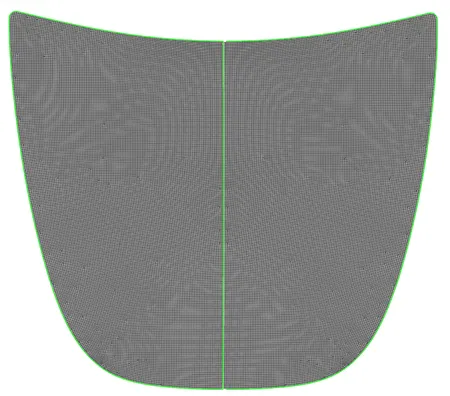
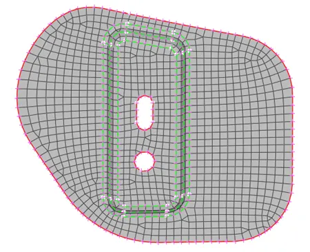
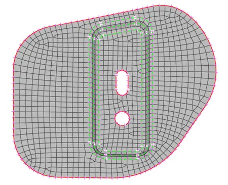
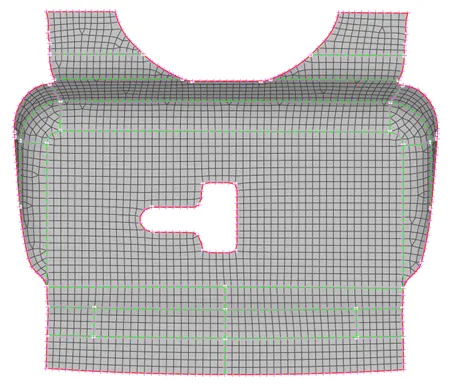
- Conclusion: The given hood model was checked for geometrical errors and topological cleanup has been performed for the model. After this mid surface has been created for the model along with property ID (thickness) for different components, mesh elements have been created on the mid surface within the quality criteria and mesh parameters. The elements have achieved the given quality criteria. The mesh has been released from the components for further FEA process. The above table refers to the number of elements generated (Quads and Trias) for the different components and overall, the Hood model (refer to Table 3).
|
Component |
Total |
Quads |
Quads% |
Trias |
Trias% |
|
Outer Panel |
50678 |
50510 |
99.67 |
168 |
0.33 |
|
Inner Panel |
42085 |
41054 |
97.55 |
1031 |
2.45 |
|
Hinge (Left and Right) |
2448 |
2360 |
96.41 |
88 |
3.59 |
|
Latch |
2895 |
2819 |
97.37 |
76 |
2.63 |
|
Overall, Hood Model |
98106 |
96743 |
98.61 |
1363 |
1.39 |
|
Table 3: Mesh Elements Achieved |
|||||
- Learning Outcomes:
- Understood the Graphic User Interface of ANSA and got used to different tools available in the software.
- Learned to check geometrical errors in the model and how to resolve those errors by auto-fix and manual edit using the topo module.
- Learned the importance of creating a mid surface for the sheet metal parts.
- Learned to assign the property ID with thickness to the different mid-surface components.
- Learned the use of the topo module to create and delete construction lines, and curves to generate better surfaces for good mesh flow.
- Learned how to mesh and edit the elements using different options in Classic mesh.
- Learned the importance of quality criteria and mesh parameters and how to make mesh elements pass the criteria using Classic mesh options.