Week 3-Meshing of Hood Challenge
- HyperMesh – Hood Model Geometry Clean Up, Midsurface Creation, PID Assignment and Mesh Generation
- AIM: Using HyperMesh preprocessor software, for a given Hood model (Outer panel, Inner panel, Latch and Hinge) check and perform geometrical cleanup, create midsurface of all the components, also assign property ID (PID), along with thickness of individual component generate mesh elements with given quality criteria and parameters (refer Table 1),
|
S. No |
Quality Criteria |
Value |
|
1 |
Target/Average length |
5 |
|
2 |
Minimum Length |
2 |
|
3 |
Maximum Length |
7 |
|
4 |
Aspect |
3 |
|
5 |
Warpage |
15 |
|
6 |
Skewness |
45 |
|
7 |
Jacobian |
0.7 |
|
8 |
Minimum Quad Angle |
45 |
|
9 |
Maximum Quad Angle |
135 |
|
10 |
Minimum Tria Angle |
30 |
|
11 |
Maximum Tria Angle |
120 |
|
10 |
Tria Percentage |
15 |
|
Table 1: Mesh Quality Criteria and Parameters |
||
- PROCEDURE:
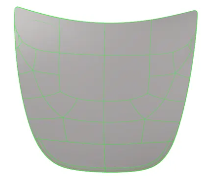
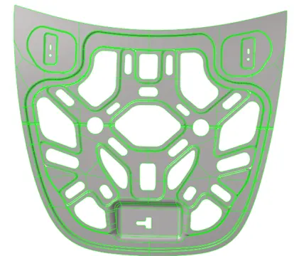
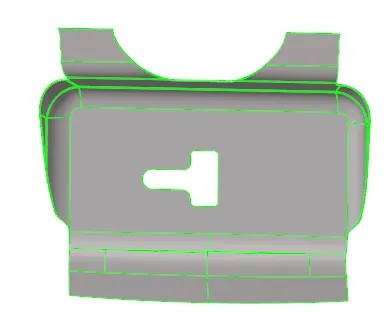
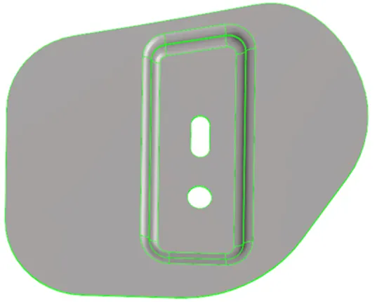
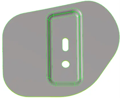
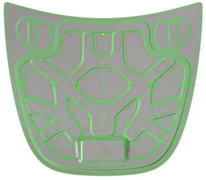
- Import CAD geometry: Imported .stp CAD model; (refer Fig.1,2,3,4,5,6)
 |
 |
|
Fig 1: Outer Panel |
Fig 2: Inner Panel |
 |
 |
|
Fig 3: Latch |
Fig 4.1: Hinge (Left) |
 |
 |
|
Fig 4.2: Hinge (Right) |
Fig 5: Overall View of Hood Model |
2. Geometry check and Auto cleanup: To check whether the geometry has been imported properly with all the features such as edges, faces etc. and to identify any deleted or duplicate features it is important to perform geometry check.
- In Main menu -> Geom - > autocleanup.
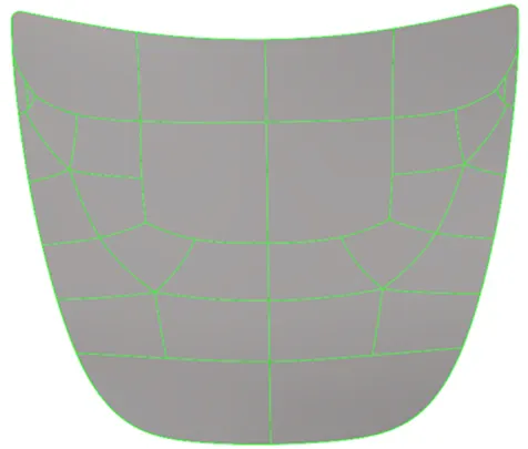
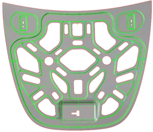
3. Midsurface Generation: The midsurface is created for individual components one by one by hiding the remaining components in the model, the components can be hide and can be worked on individually.
The components generated can be kept in different collectors with the components names.
- In Main menu -> Geom -> Midsurface. refer fig (6,7,8,9.1,9.2,10)
 |  |
|---|---|
| Fig6: Outer Panel | Fig7: Inner Panel |
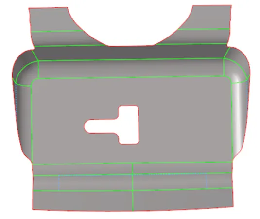 | |
| Fig8: Latch | Fig9.1:Hinge (Left) |
| 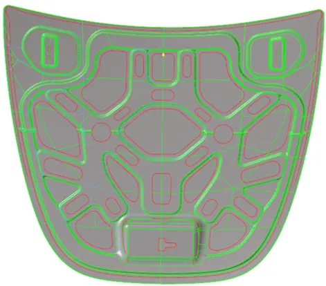 |
| Fig9.2: Hinge (Right) | Fig10: Overall View of Hood Model |
4. Assigning property to the component: The properties are created fo the components respectively. After creating properties, it is assigned to their respective components.
- To create a property collector, right-click on tab area -> click on property -> assign name to the property -> enter thickness value.
- To assign property to component, In tab area -> click on component -> assign the property respectively.
5. Setting up Quality Criteria and Parameters: The quality criteria and mesh parameters are set up before generating mesh to evaluate the mesh quality. The quality criteria and parameters can be saved in the folder for future use.
- In Menu bar -> preferences -> criteria file settings.
- In Menu bar -> preferences -> parameters file settings.
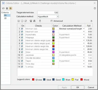 |
|---|
| Fig11: Criteria file settings |
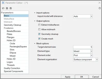 |
| Fig12: Parameter file settings |
6. Generating Mesh Elements : The mesh is generated on each component individually. In case of symmetrical component, Half mesh can be created and reflected afterwards. In the last step, after confirming the mesh parameters, quality and property ID, the model is prepared,. In Tools -> checkelem -> can click on each criteria and check for failed elem.
- In Main menu -> 2d -> automes. refer (Fig. 13,14,15.1,15.2,16)
- The mesh generated should be edited till the model achieves:
- the better mesh flows.
- minimum trias obtained.
- Trias at fillet, edges, and holes removed.
- back to back opposite trias are removed.
- rotational quads are removed.
- To reflect the mesh, In Main menu -> Tools -> reflect(duplicate the elements and reflect).
- To equivalence the mesh after reflecting, In Main menu -> 2d -> edges(shift+F3).
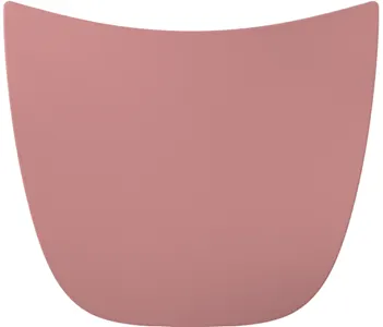 | 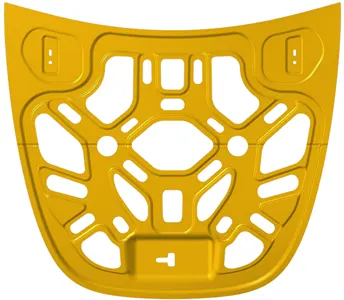 |
|---|---|
| Fig13: Outer Panel | Fig14: Inner Panel |
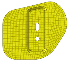 | 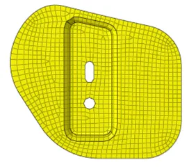 |
| Fig15.1: Hinge (Left) | Fig15.2: Hinge (right) |
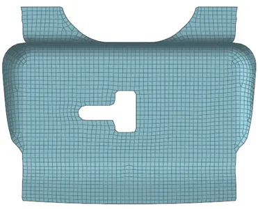 | |
| Fig16: Latch | |
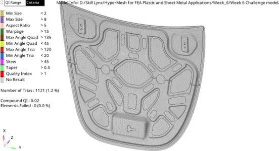
- Conclusion : The given hood model was checked for geometrical errors and topological cleanup has been performed for the model. There was no geometry errors found in the model. There was no geometry errors found in the model. After this mid surface has been created for the model along with property ID (thickness) for different components, mesh elements have been created on the midsurface within the quality criteria and mesh parameters. The elements have acheived the given quality criteria.
 |
|---|
| Fig17: Quality Criteria |
Learning Outcomes:
- Understood the graphic interface of Hypermesh and got used to different tools available in the software.
- Learned to check geometrical errors in the model and how to resolve those errors by autocleanup and quick edit.
- Learned the importance of creating a mid surface for the sheet metal parts.
- Learned to assign the property ID with thickness to the different midsurfaces components.
- Learned to use geom and tools in the main menu bar to create and delete construction lines, and curves to generate better surfaces for good mesh flow.
- Learned how to mesh and edit the elements using different 2d mesh options.
- Learned the importance of quality criteria and mesh parameters and how to make mesh elements pass the criteria using classic mesh options.
Model Link: https://drive.google.com/file/d/1tSCDeeX_Pwi5ccNAP1zwTyR4Lz8qpAqs/view?usp=drive_link