Week 3 - 2D meshing for sheet metal
AIM:
To mesh the given sheet metal in ANSA.
OBJECTIVE:
To take the mid surfaces for all the components in the model and mesh these midsurfaces with given quality criteria and assign the thickeness.
PROCEDURE:
1.CHECK FOR UNDEFINED MATERIAL:
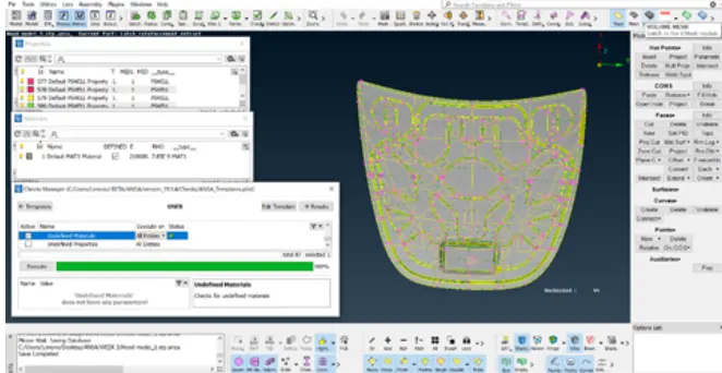
1.PROPERTIES: In this we can observe how many components are there in the geometry according to how many property ID's are present.
2.MATERIALS: In this we can see that how many material properties are avaliable and are they defined or not.
3.Then check for undefined materials in checks manager.
2.GEOMETRY CHECK UP:
1.Here we have to check the geometry for the CAD model before going to mesh.
2.Goto Checks Manager > Geometry.
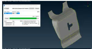
LATCH:
1.For the Latch components there is no error occured.
LEFT HINGE:
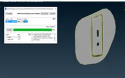
1.For the Left Hinge components there is no error occured.
RIGHT HINGE:
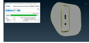
1.For the Right Hinge components there is no error occured.
EXTERNAL PANEL:
1.For the External panel component there is no error occured.
INNER PANEL:
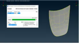
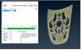
1.For this component the error occured.
2.By selecting the error displayed and fix the issue.
3.After this process the error gets rectified.
3.CHECKING THE THICKNESS OF THE COMPONENTS:
1.Next step we wants to check the thickness of each component in order to assign it in properties.
2.The thickness of the Five components are,
LATCH = 1.2
L HINGE = 1.2
R HINGE = 1.2
EXTERNAL PANEL = 0.75
INTERNAL PANEL = 0.75.
4.MIDSURFACING:
1.Generally there are 2 types of mid surface can be extracted namely Auto mid and Manual mid.
2.For this challenge we use manual mid surfacing for the Goto FACES > OFSET and select the region.
3.We can also use Feature Area Command as there are multiple regions to select.
4.Future area command gives the single click slection of out region of interest So that it reduces the selection time.
5.Goto Faces > Ofset > Feature area at 40 Degree.
5.SIZING PERIMETER, DEFEATURING AND MESH PREPARATIONS:
1.Change all the perimeter element distance to 5mm.
2.Confirm whether perimeter element distances are in acceptable range.
3.For all the extracted component the same procedure follows.
6.ASSIGING QUALITY CRITERIA AND MESHING PARAMETER:
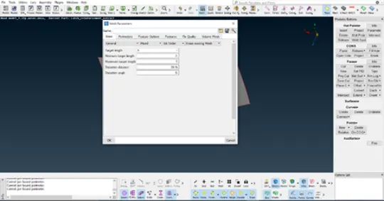
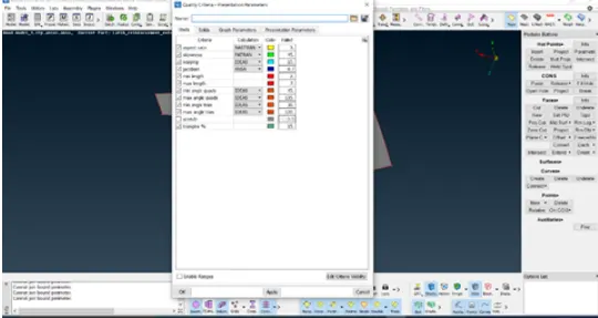
1.Declaring the given condition in the Quality critera and Meshing Parameter.
7.MESHING:
1.For good mesh quality divide the domain into appropriate section by using Cut (or) Join command.
2.To apply mesh use Best Mesh > Mesh Generation, and to remove mesh use Erase > Mesh Generation.
3.Clear the mesh quality by the combination of Reconstruction > Shell Mesh.
OUTPUT:
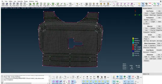
1.Latch:
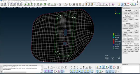
2.Hinges:
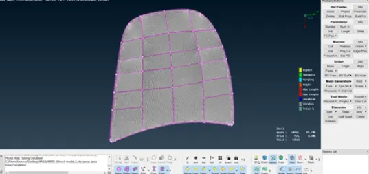
3.External Panel:
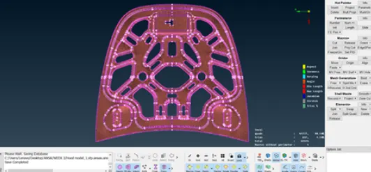
4.Inner Panel:
OBSERVATION:
Thus the midsurfacing, meshing and assiging thickness is done sucessfully.
RESULT:
Thus the sheet metal is meshed using ANSA is performed sucessfully.