Week 3
Meshing of car hood model using ANSA
Aim
For the given component, check for the geometrical errors and mesh with the given element quality criteria. After meshing the component, the thickness has to be assigned.
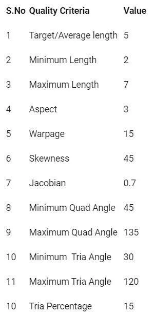
Assigned quality criteria
Reason for geometry cleanup in ANSA
The very first step to start any CAE project is to import the CAD data. While the importation of CAD data, there occurs some geometric issues. Some geometric issues are,
- The gap present between adjacent surfaces.
- Two surfaces often contain gaps, misalignment, overlaps, etc.
- Appearance of free edges in the geometry.
To eliminate the geometric issues, the first step is to repair the CAD model by,
- Deleting the untrimmed surfaces
- Close missing surfaces
- Equivalence free edges
- Delete duplicate surfaces
Benefits of repairing
- Eliminating the errors in CAE model.
- Ensuring proper connctivity of mesh
Procedure
The car hood model was provided with stp format and imported in ANSA environment, and each part was observed for topology cleanup.
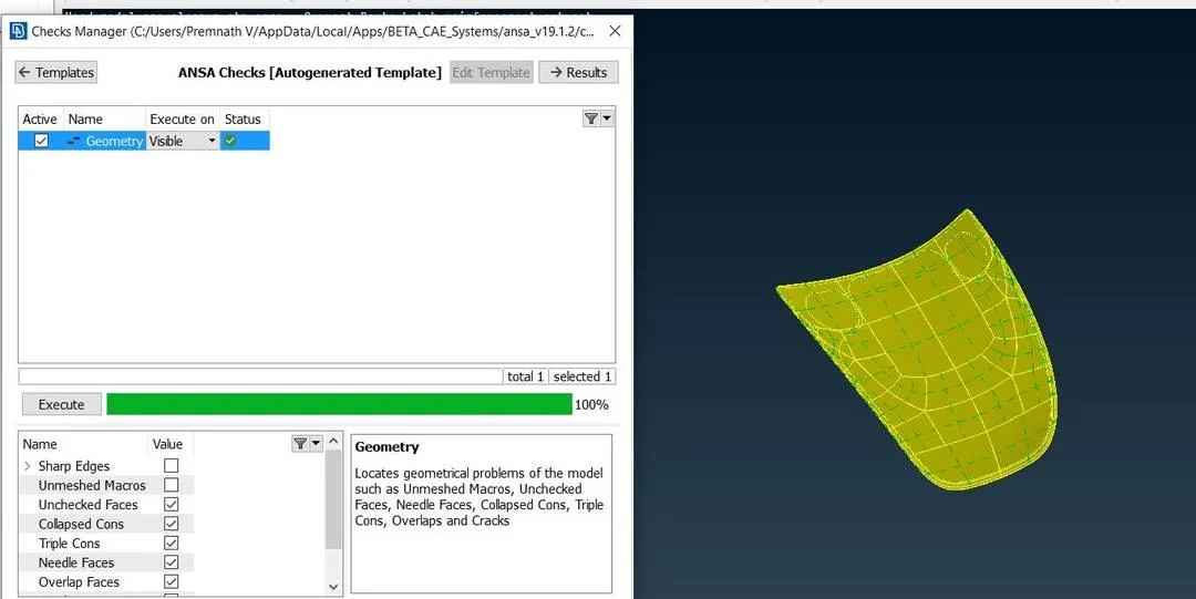
Fig 1 Geometry cleanup of the car hood model
Latch Reinforcement
Steps:
- The latch reinforcement component was taken into consideration by keeping all other components hidden. The separate property (Set PID) was assigned to the latch reinforcement part and the model was kept locked for ease of operations.
- After successful completion of geometry cleanup, Midsurface -> Skin option from the ‘Faces’ tab extraction operations were performed. The selected model was divided into red, green, and blue regions depicting the negative, positive and middle areas respectively.
- The image below shows the midsurface extraction of latch reinforcement component. After the midsurface extraction, the geometry was checked for any errors before meshing using checks-> geometry.
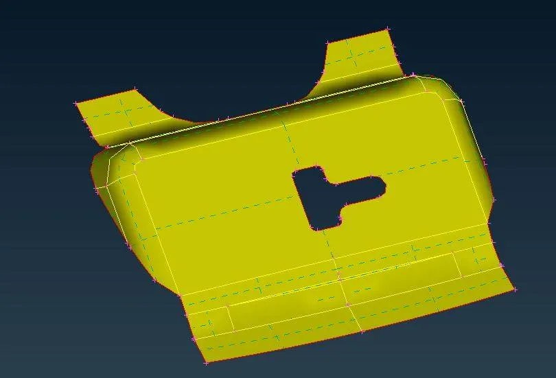
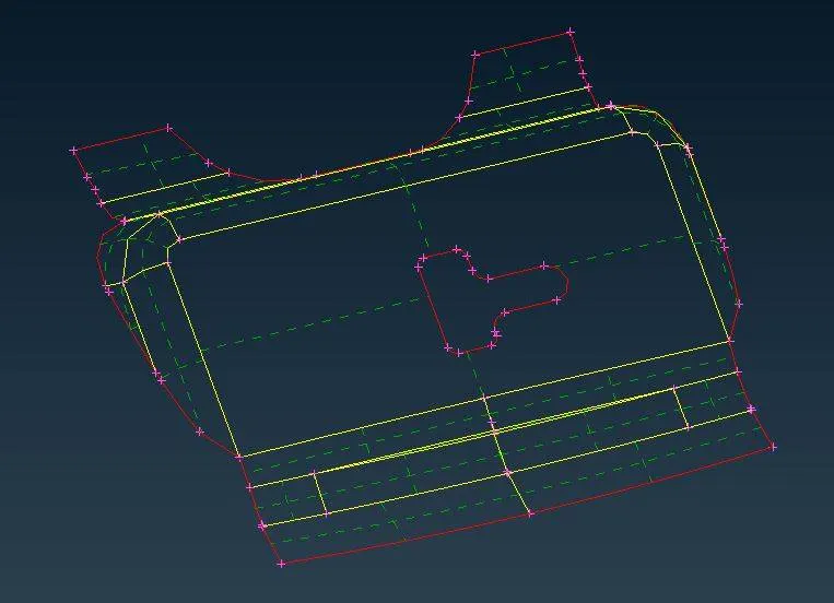
Fig 2 Midsurface extraction of Latch reinforcement
- The model has to be meshed with a target length of To ensure the target length, Perimeters - > Length option was used in order to divide the section of the model with 5 mm each.
- Under Mesh generation-> Best mesh option was used to obtaine a mesh grid pattern on the model. In order to get rid of failing elements and also to improve the flow pattern of mesh, shell mesh-> reconstruct option was used.
- Since tria elements is more stiffer than orthogonal elements, getting rid of tria elements is effective over the perimeter of the model. Using hybrid options like split, join, swap under elements tab was used to get rid of tria elements.
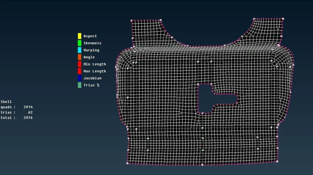
Fig 3 Mesh pattern on the surface of latch reinforcement
Hinge Reinforcement
Steps:
- After completing the latch reinforcement meshing, both the hinges present in the car hood model was meshed by following the same procedure.
- Intially, the mid surface was extracted, and topology cleanup check was done on the midsurface. All the unnecessary CONs were removed using the Macros-> Cut or Join option from the mesh module.
- To obtain a good mesh flow pattern on the surface of hinges, the same mesh procedure of latch reinforcement was performed.
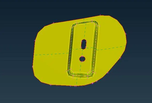
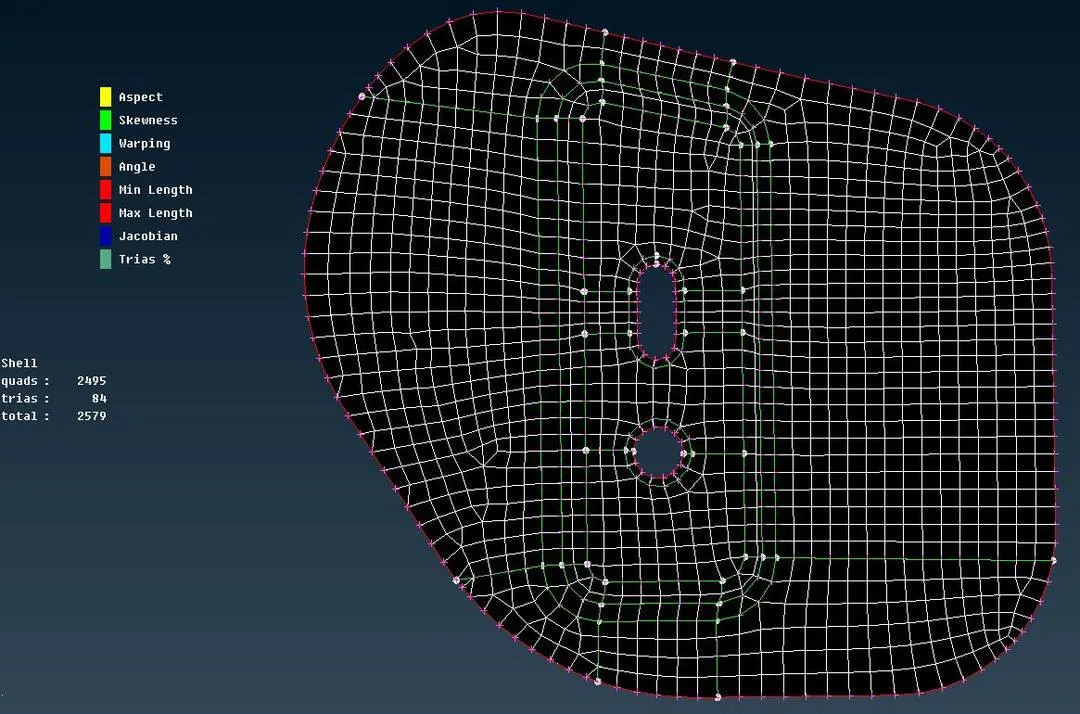
Fig 4 Midsurface extraction and Mesh pattern of hinge reinforcement
Outer extract
Steps:
- Once completing the meshing of latch and hinge reinforcement, the outer extract of the hood was meshed by following the same procedure as above.
- In this case, since the geometry of the outer extract was symmetrical, meshing the one half and replicating the mesh to the other half using the mirror option was feasible.
- To this component, the midsurface was extracted first and then topology cleanup was performed only to one half. Midsurface extraction was completed using Faces-> Midsurface-> skin option in the Topo module.
- Once completion of midsurface extraction, the topology cleanup was performed on the component.
- The component was cut in half using the plane cut option from the topo-> faces. A cut was made exactly at the center using a plane. The half of the components were hidden using NOT command.
- Under Mesh generation-> Best mesh option was used to obtaine a mesh grid pattern on the model. In order to get rid of failing elements and also to improve the flow pattern of mesh, shell mesh-> reconstruct option was used.
- Since tria elements is more stiffer than orthogonal elements, getting rid of tria elements is effective over the perimeter of the model. Using hybrid options like split, join, swap under elements tab was used to get rid of tria elements.
- After obtaining the good mesh pattern, all the elements had to be mirror the other half of the component. To perform this operation, Transform-> copy-> symmetry option used. Using the mirror by 3 points command, alll the elements were copied and mirrored on the other side.
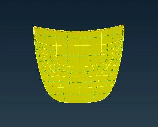
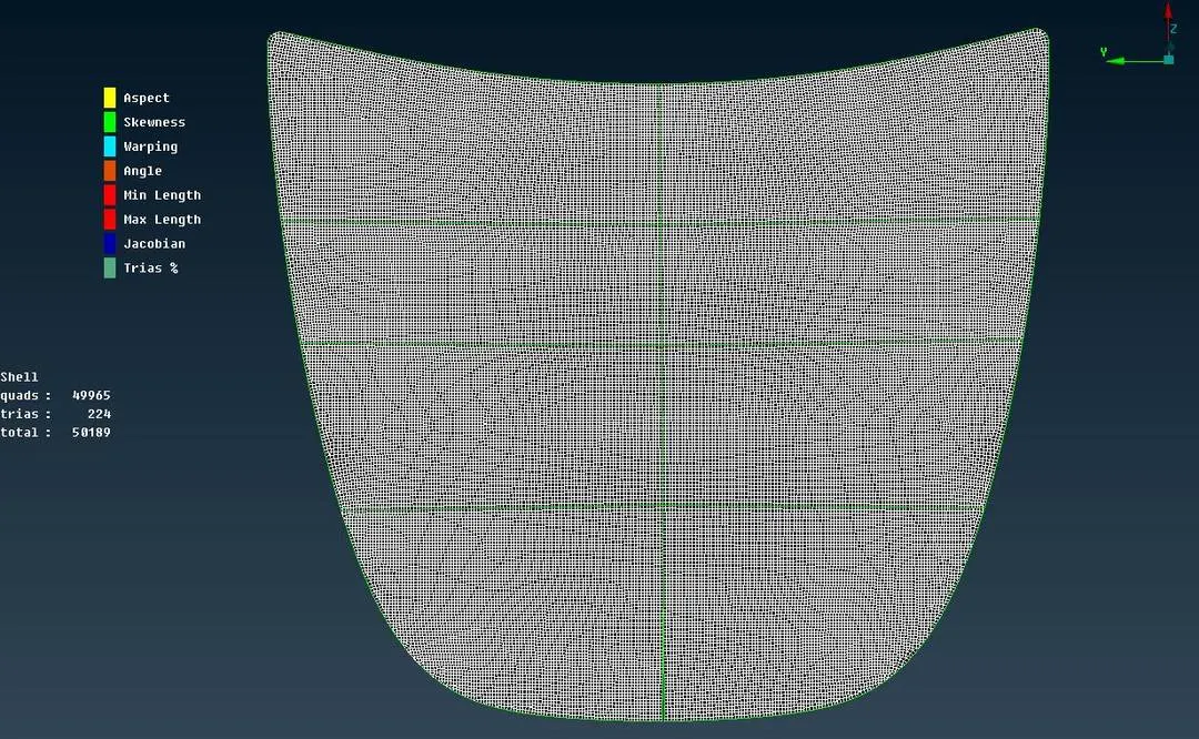
Fig 5 Midsurface extraction and Mesh pattern of outer extract
Inner extract
Steps:
- Once completing the meshing of latch, hinge reinforcement, and the outer extract of the hood, the inner extract was meshed by following the same procedure as above.
- In this component, there unnecssary hotpoints and CONs were removed and manual cuts wee created according to the geometry for a better mesh flow.
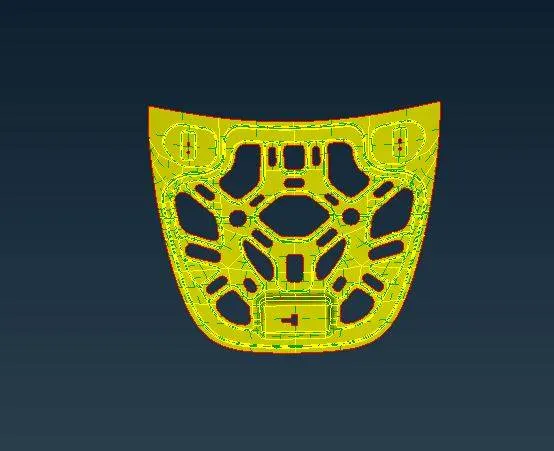
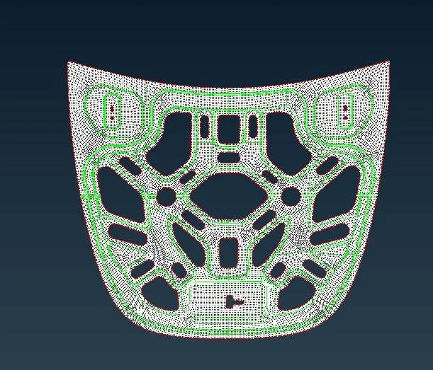
Fig 6 Midsurface extraction and Mesh pattern of inner extract
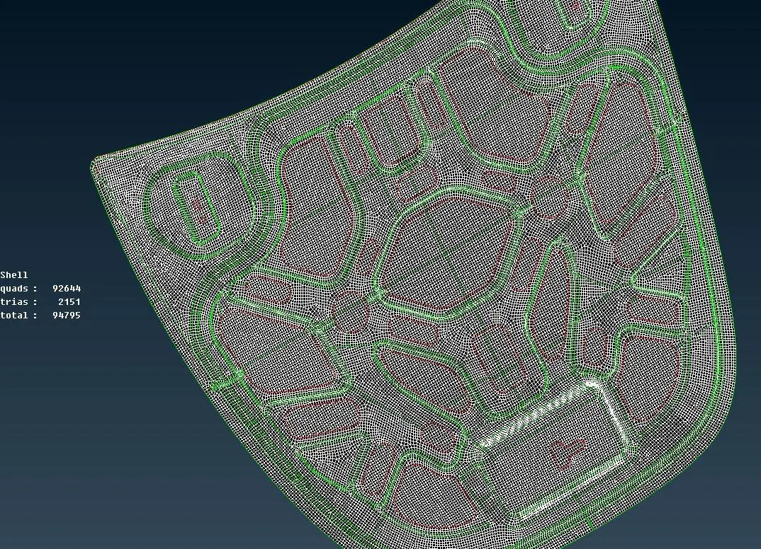
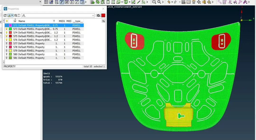
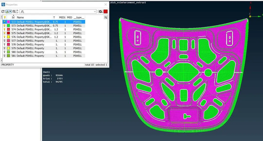
Fig 7 Meshing of car hood model
Result and conclusion
- The geometry cleanup process was performed on car hood model by correcting the free edges and deleting the unnecessary triple CONs.
- The mesh wass been carried out on mid surface by keeping target size of 5mm.
- With target size of 5mm, the element check criteria on minimum and maximum length was performed on car hood model.