Assignment 5
Assignment 5
Objective
Create the mesh for bumper assembly, mesh size should be 6mm.
- Run the crash tube model as it is.
- Change the Inacti=6 and run.
- Create the type 11 contact and run.
- Remove both notches and remove boundary condition on rigid body node then run.
- Create a new notch in the middle, select the whole section and run.
- Create a new notch with nodes only from opposing 2 faces and run.
Note:
Plot RWALL forces, contact forces, internal energy and Create TH/PART for all parts and compare results for all cases.
Comment your thought on why there is a change in the internal energies.
How does the notch affect the results?
Plot energies and note any difference.
Meshing bumper assembly
Case set up and explanation
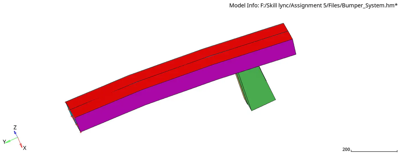
Fig 1. Bumper assembly model
- Fig 1. Model 1 opened in hypermesh window.
- Check surface edges in the model. Remove the free edges that appear between two adjacent surfaces. Use surface edit option, to trim the surfaces.
- Click on 2D -> Automesh -> element size (6 mm) -> mesh.
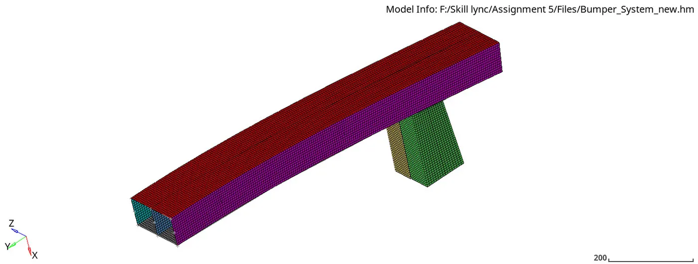
Fig 2 Meshing of bumper assembly
Interface / Contact modeling
Interfaces are defined to model how parts interact when they come into contact with each other. Several interfaces are available in Radioss and each interface is distinguished with a type number.
The important interface types/method available in RADIOSS for crash structure applications
- Interface penalty method
- TYPE 7, variable stiffness, node to surface contact
- TYPE 11, variable stiffness, edge to edge contact
- TYPE 19 = TYPE 7 + TYPE 11
- TYPE 24, linear stiffness, node to surface, and surface to surface contact
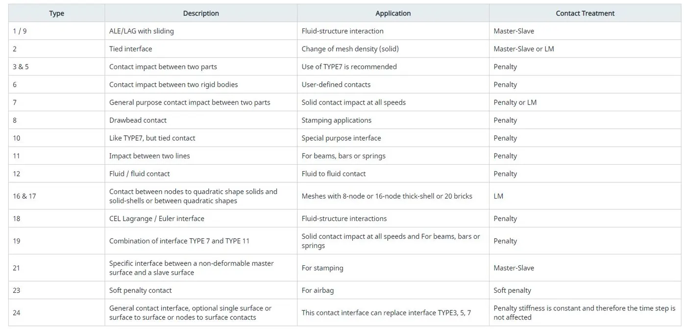
Table 1 Interfaces in RADIOSS
Case 1: Run the crash tube model as it is
- The given starter input file “Crush_tube_0000.rad” is imported into hypermesh using the ‘import solver desk’ option. In this model, the material law used is JOHNSON-COOK / ZERILLI-ARMSTRONG ELASTOPLASTIC.
- Here, the contact interfaces used are TYPE 2 and TYPE 7. Interface TYPE2, also called tied interfaceis a nodal constraint to rigidly connect a set of slave nodes to a master surface. The slave nodes forces and moments are transferred to the master nodes, and then slave nodes are positioned kinematically according to the motion of the master nodes.
- Interface TYPE7 is a general-purpose interface and can simulate all types of impact between a set of nodes and a master surface. The main advantage of interface TYPE7 is that the stiffness is not constant and increases with penetration preventing the node from going through the shell mid-surface. This solves many bad contact treatments.
- In this type, the interface penalty method is used. This method treats the behavior between the slave nodes and master segments as springs that generate the resistive forces as a function of penetration.
- Click on Analysis from menu pages -> Radioss to perform the simulation.
- “Crush_tube_0001.out” is opened to check the number of cycles, energy errors, and mass errors to determine whether the performed simulation is feasible or not.
Total number of cycles: 83691
Energy errors: -3.8 %
Mass error: 0.000
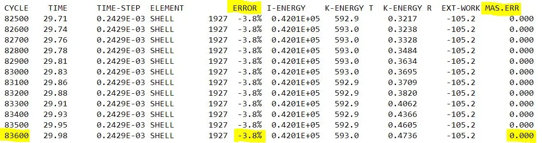
Fig 3 Result checking
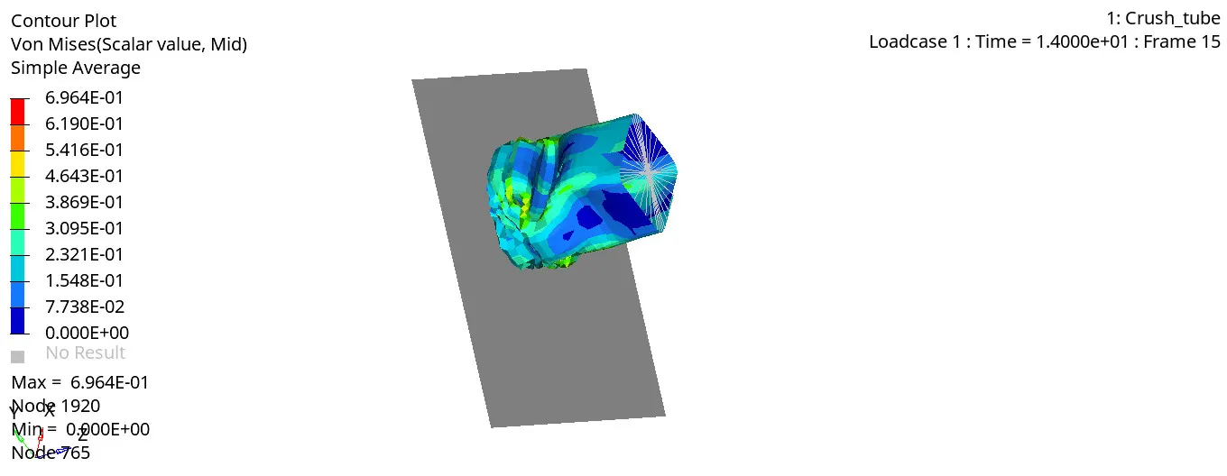
Fig 4 Von-Mises stress
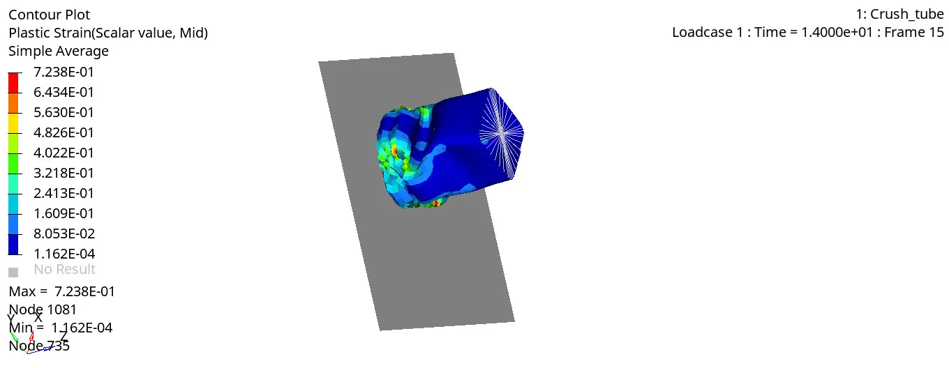
Fig 5 Plastic strain
The energy error is -3.8%, well within the limits for QEPH elements. Hence, it is good to go for further analysis.
The maximum amount of Von-Misses stress is found to be 6.964e-1 KN/ mm².
The maximum amount of plastic strain is found to be 0.7238
To rigid wall forces, contact forces and internal energies, open Crash_tubeT01 file in hypergraph 2D window.
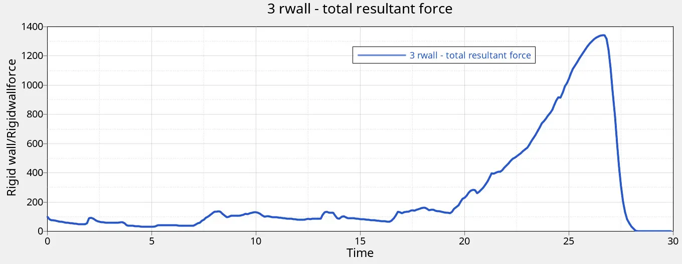
Fig 6 Rigid wall force
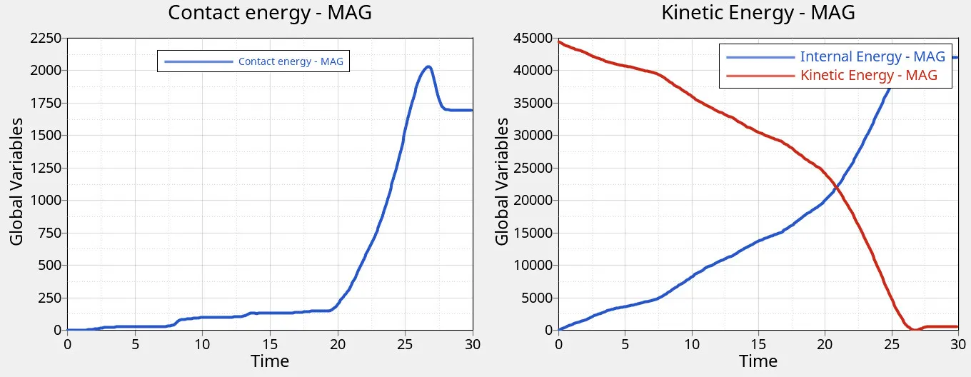
Fig 7 Contact energy, internal energy and kinetic energy
The maximum rigid wall total resultant force is found to be 1340.659 KN
The maximum contact energy is found to be 2031.59 J
The maximum internal energy and kinetic energy are found to be 42269 J & 44400 J respectively.
Case 2: Change the Inacti=6 and run
In this case, keeping all parameters unchanged from case 1 expect for changing Inacti=6 on TYPE 7 interface in the hypercrash window. Special treatment for initial penetrations can be accomplished through the use of the Inacti flag. It is possible to remove penetrated nodes from the interface or to remove the master segments relating to the penetrated nodes. Both treatments allow getting rid of initial penetrations very easily, but they may lead to poor results if the number of penetrated nodes is large. To avoid high frequency effects Inacti = 6 is recommended.
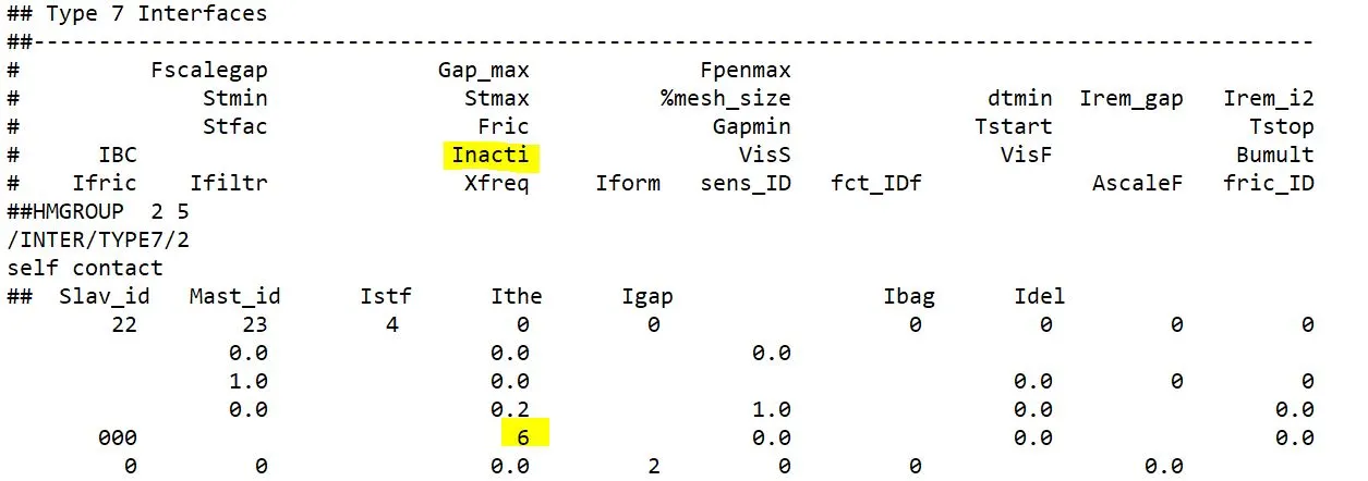
Fig 6 TYPE 7 Interfaces
After making the change in hyper crash, click File -> export -> Crush_tube_0000.rad (replace the original starter desk file and engine file).
“Crush_tube_0001.out” is opened to check the number of cycles, energy errors, and mass errors to determine whether the performed simulation is feasible or not.
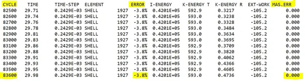
Fig 7 Result checking
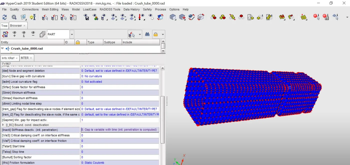
Fig 8 Crash tube in hypercash window
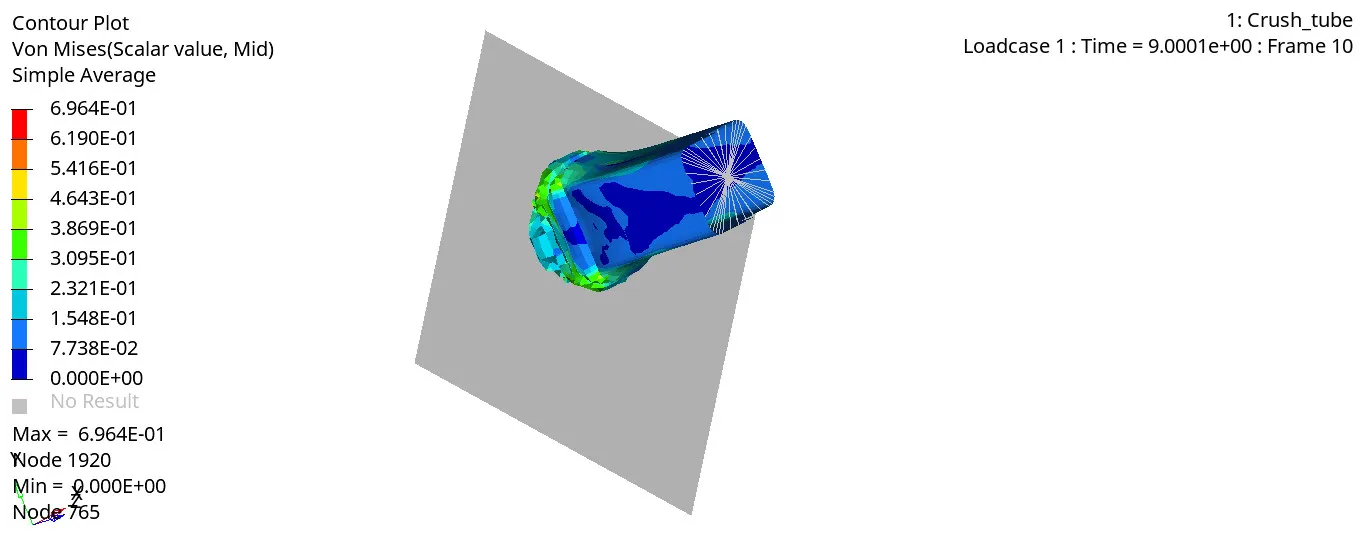
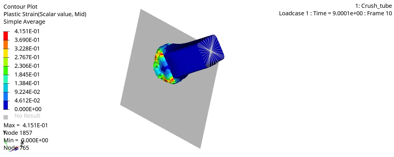
Fig 9 Von Misses and plastic strain simulation
The energy error is -3.8%, well within the limits for QEPH elements. Hence, it is good to go for further analysis.
The maximum amount of Von-Misses stress is found to be 6.964e-1 KN/ mm².
The maximum amount of plastic strain is found to be 4.151
To rigid wall forces, contact forces and internal energies, open Crash_tubeT01 file in hypergraph 2D window.
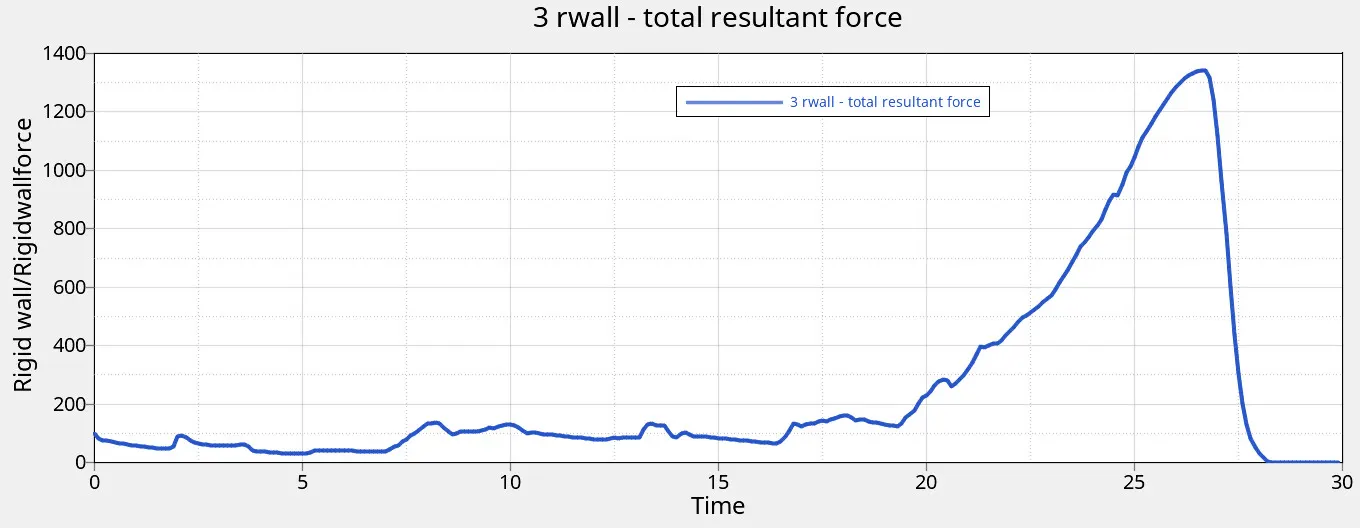
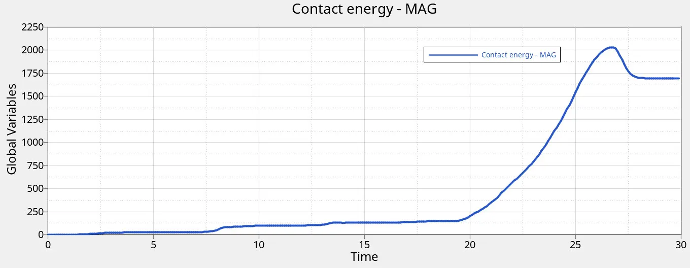
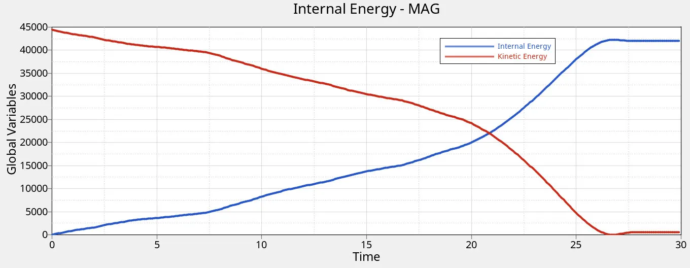
Fig 10 Rigid wall force, Contact energy, internal energy and kinetic energy
The maximum rigid wall total resultant force is found to be 1340.659 KN
The maximum contact energy is found to be 2031.59 J
The maximum internal energy and kinetic energy are found to be 42269 J & 44400 J respectively.
Case 3: Create the TYPE 11 contact and run
In this case, keeping all parameters unchanged from case 1, create TYPE 11 contact in hypercrash window.
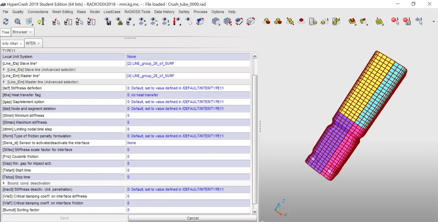
Fig 11 Crash tube in hypercash window
/INTER/TYPE11
This interface simulates impact between edge to Edge or lines. A line can be a beam or truss element or a shell edge or spring elements.
The interface properties are:
- Impacts occur between a master and a slave line.
- A slave line can impact on one or more master lines.
- A line can belong to the master and the slave side. This allows self-impact.
- This interface can be used in addition to /INTER/TYPE7 to solve the edge to edge limitation of interface TYPE7.
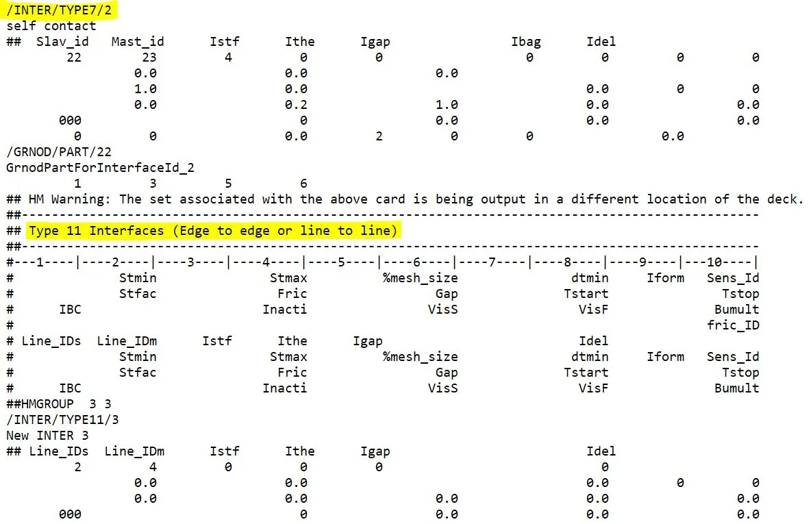
Fig 12 TYPE 7 and TYPE 11 interfaces
- After making the change in hyper crash, click File -> export -> rad (replace the original starter desk file and engine file).
- “Crush_tube_0001.out” is opened to check the number of cycles, energy errors, and mass errors to determine whether the performed simulation is feasible or not
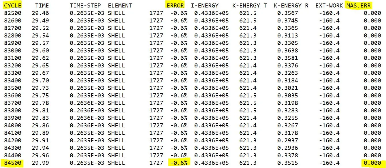
Fig 13 Result checking
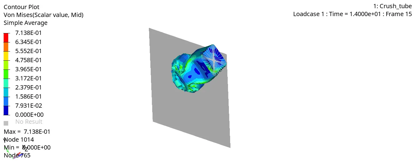
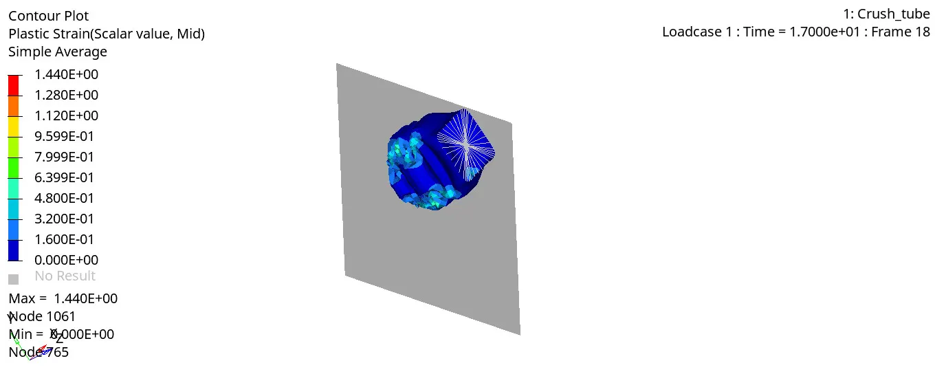
Fig 14 Von Misses and plastic strain simulation
The energy error is -0.6%, well within the limits for QEPH elements. Hence, it is good to go for further analysis.
The maximum amount of Von-Misses stress is found to be 7.138e-1 KN/ mm².
The maximum amount of plastic strain is found to be 1.440
To rigid wall forces, contact forces and internal energies, open Crash_tubeT01 file in hypergraph 2D window.
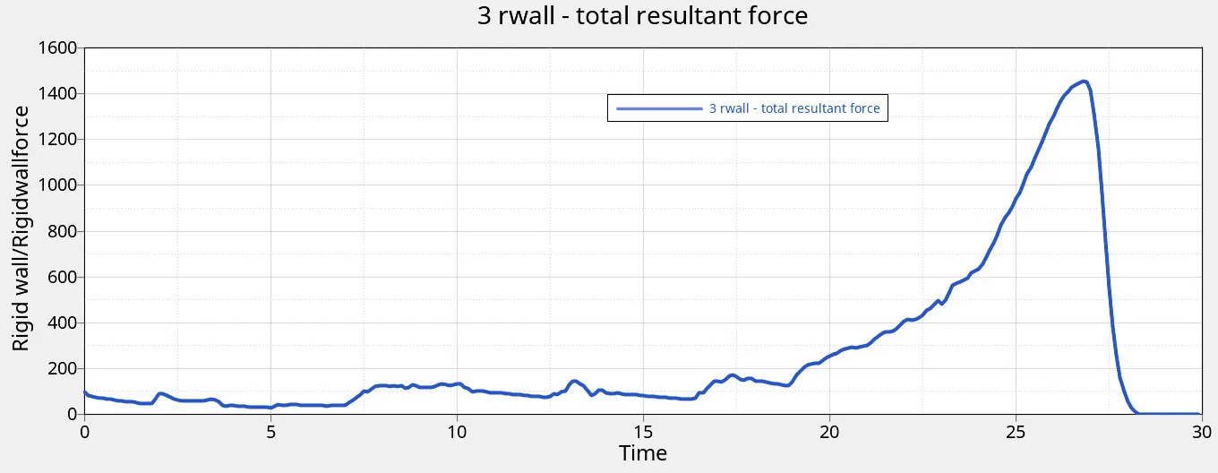
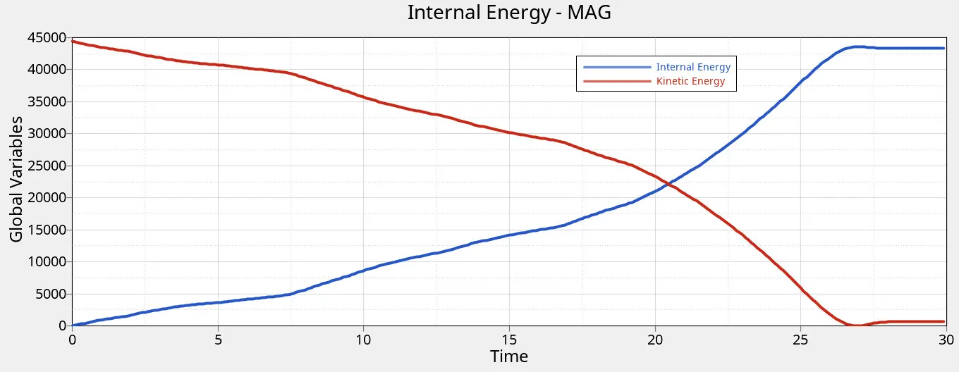
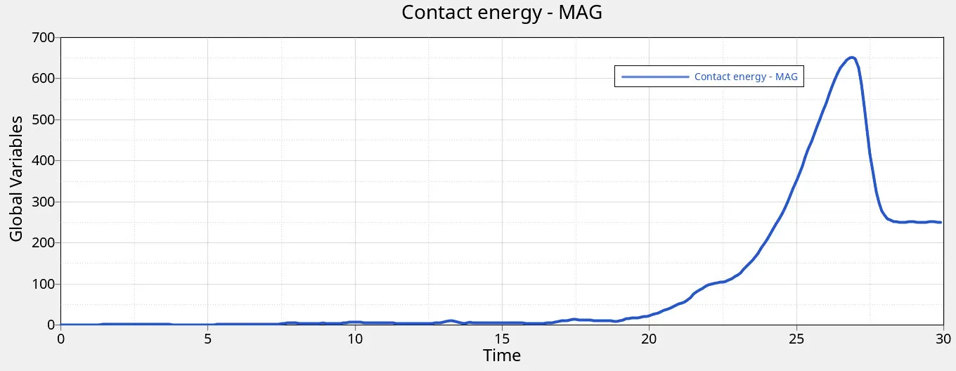
Fig 15 Rigid wall force, Contact energy, internal energy and kinetic energy
The maximum rigid wall total resultant force is found to be 1454.17 KN
The maximum contact energy is found to be 2031.59 J
The maximum internal energy and kinetic energy are found to be 43581J & 44400 J respectively.
Case 4: Remove both notches and remove boundary condition on rigid body node then run
In this case, all notches present in case 1 model is removed. Using node edit-> align node command, notches are removed. Further, BCS card is removed from solver browser in hypermesh window.
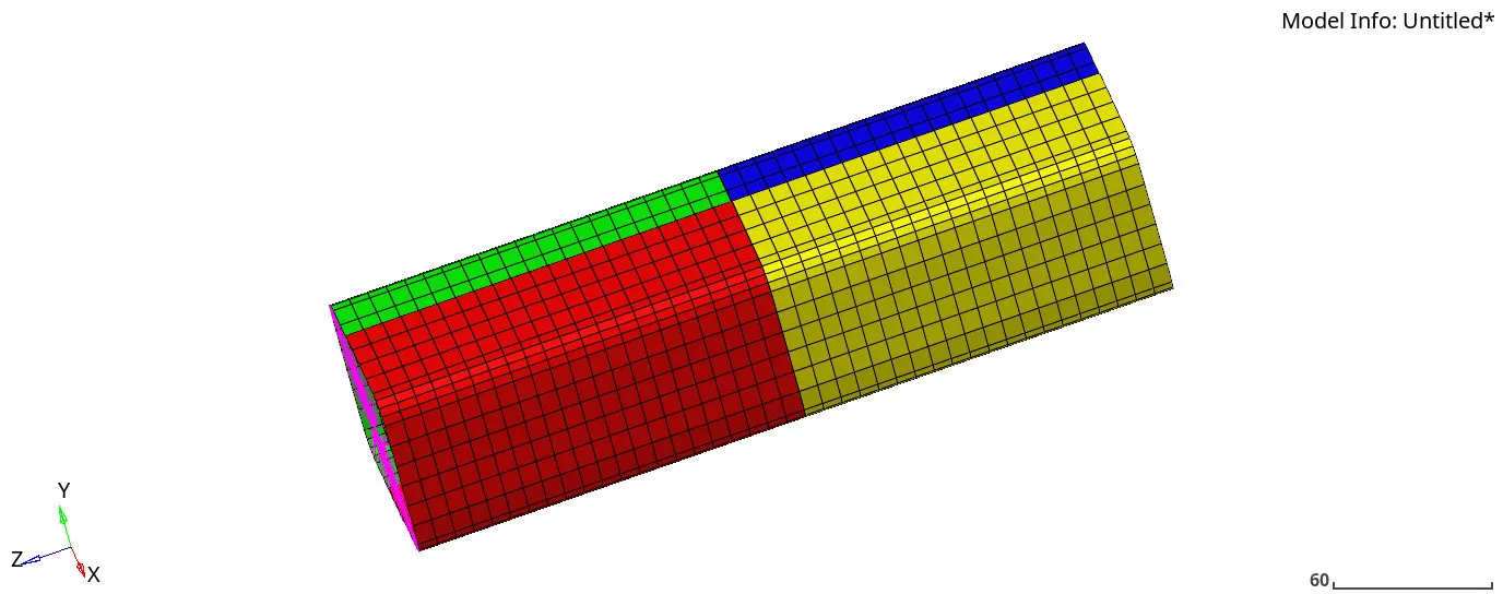
Fig 16 Crash tube without notches

Fig 17 Result checking
The energy error is -3.0%, well within the limits for QEPH elements. Hence, it is good to go for further analysis.
The maximum amount of Von-Misses stress is found to be 4.566e-1 KN/ mm².
The maximum amount of plastic strain is found to be 1.366
To rigid wall forces, contact forces and internal energies, open Crash_tubeT01 file in hypergraph 2D window.
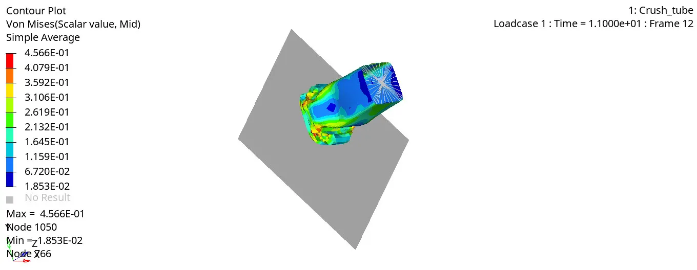
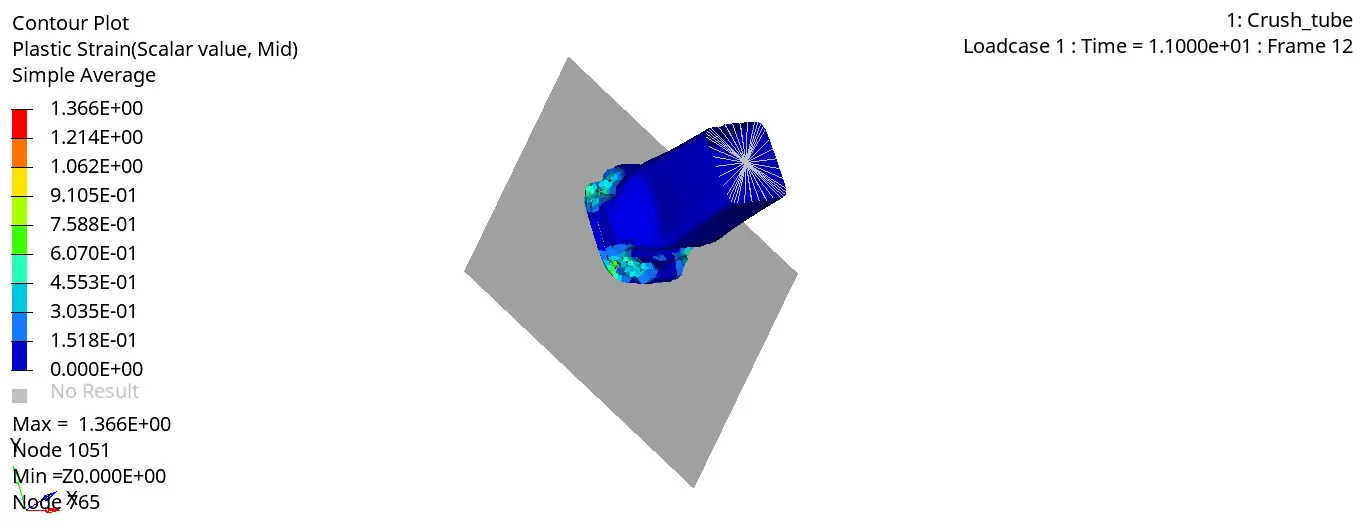
Fig 18 Von Misses and plastic strain simulation
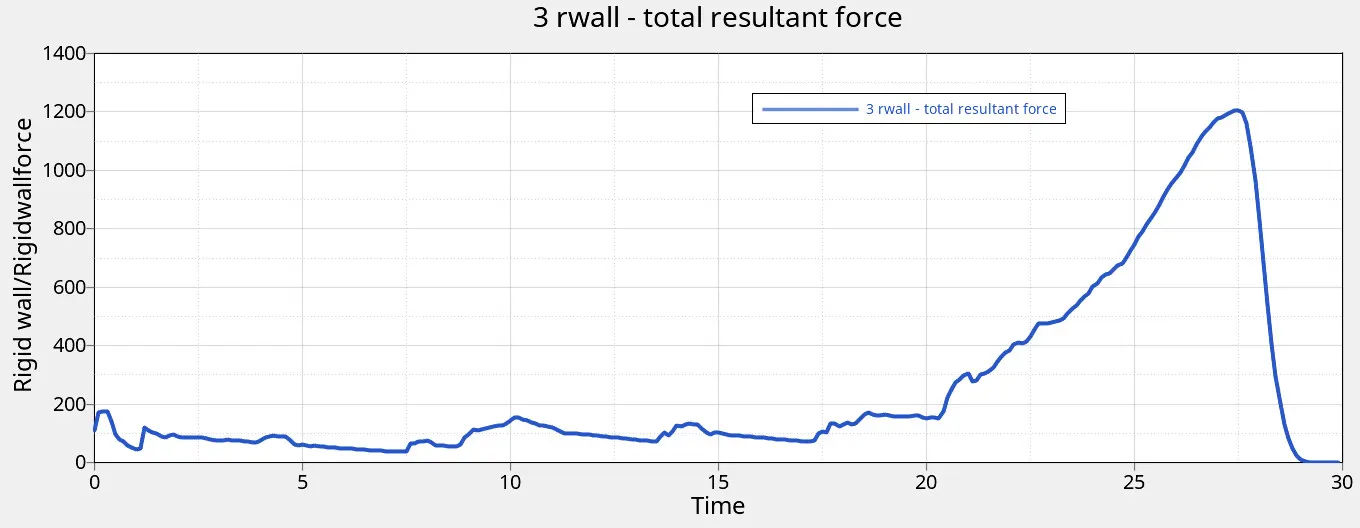
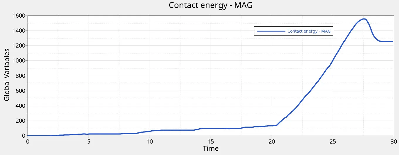
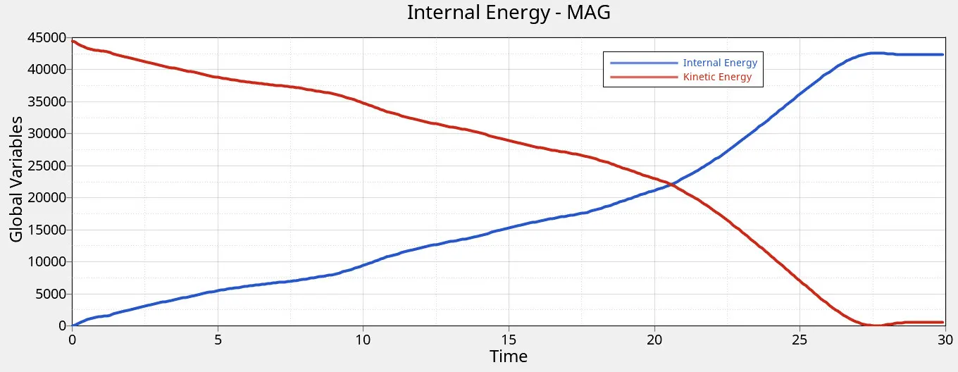
Fig 19 Rigid wall force, Contact energy, internal energy and kinetic energy
The maximum rigid wall total resultant force is found to be 1203.61 KN
The maximum contact energy is found to be 1557.30 J
The maximum internal energy and kinetic energy are found to be 43594 J & 44400 J respectively.
Case 5: Create a new notch in the middle, select the whole section and run
In this case, the notch is created in the middle of the crush tube model from previous case, while other parameters were kept constant.
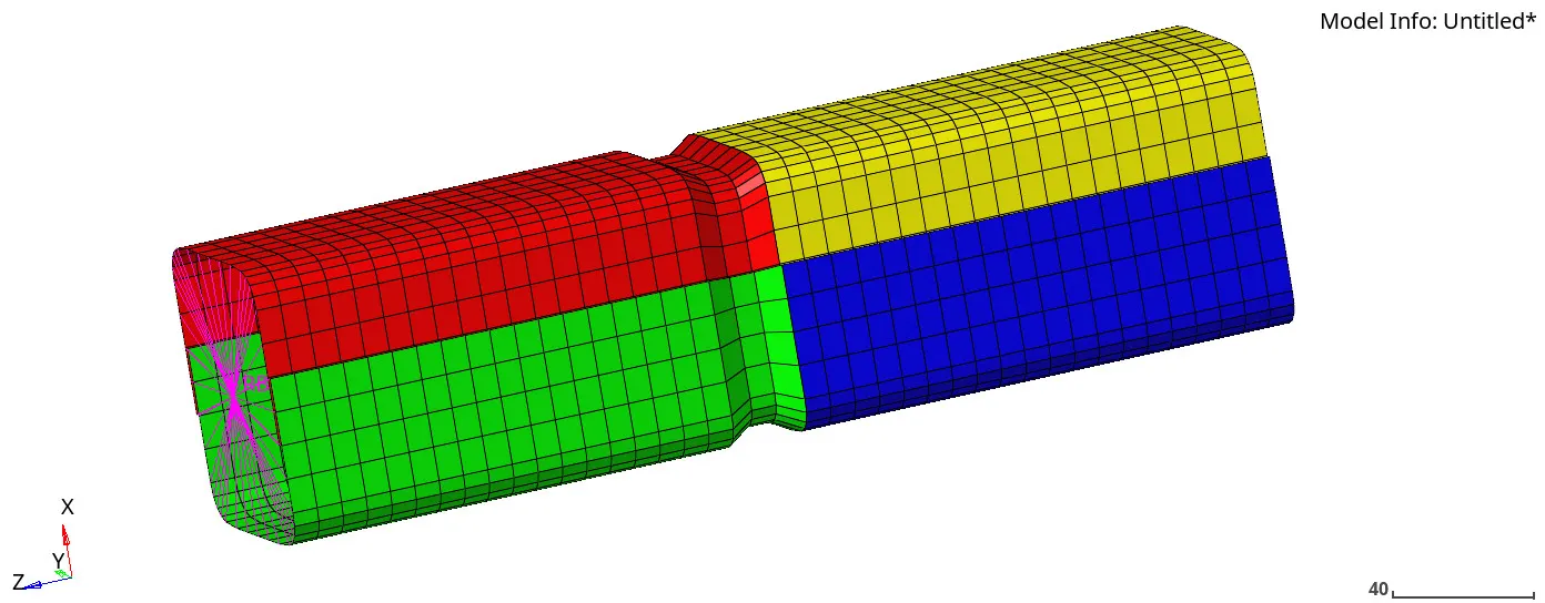
Fig 20 Crash tube with notch in middle
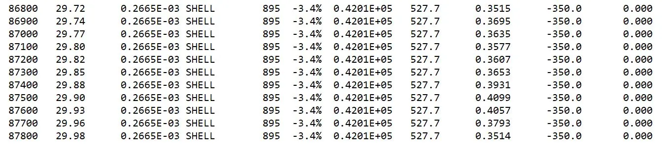
Fig 21 Result checking
The energy error is -3.4%, well within the limits for QEPH elements. Hence, it is good to go for further analysis.
The maximum amount of Von-Misses stress is found to be 6.299e-1 KN/ mm².
The maximum amount of plastic strain is found to be 1.123.
To rigid wall forces, contact forces and internal energies, open Crash_tubeT01 file in hypergraph 2D window.
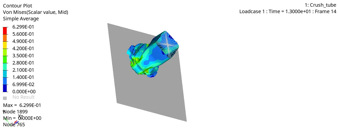
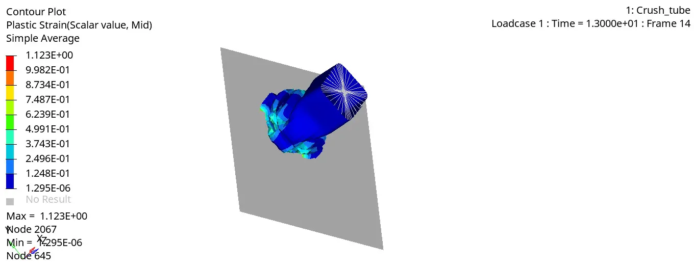
Fig 22 Von Misses and plastic strain simulation
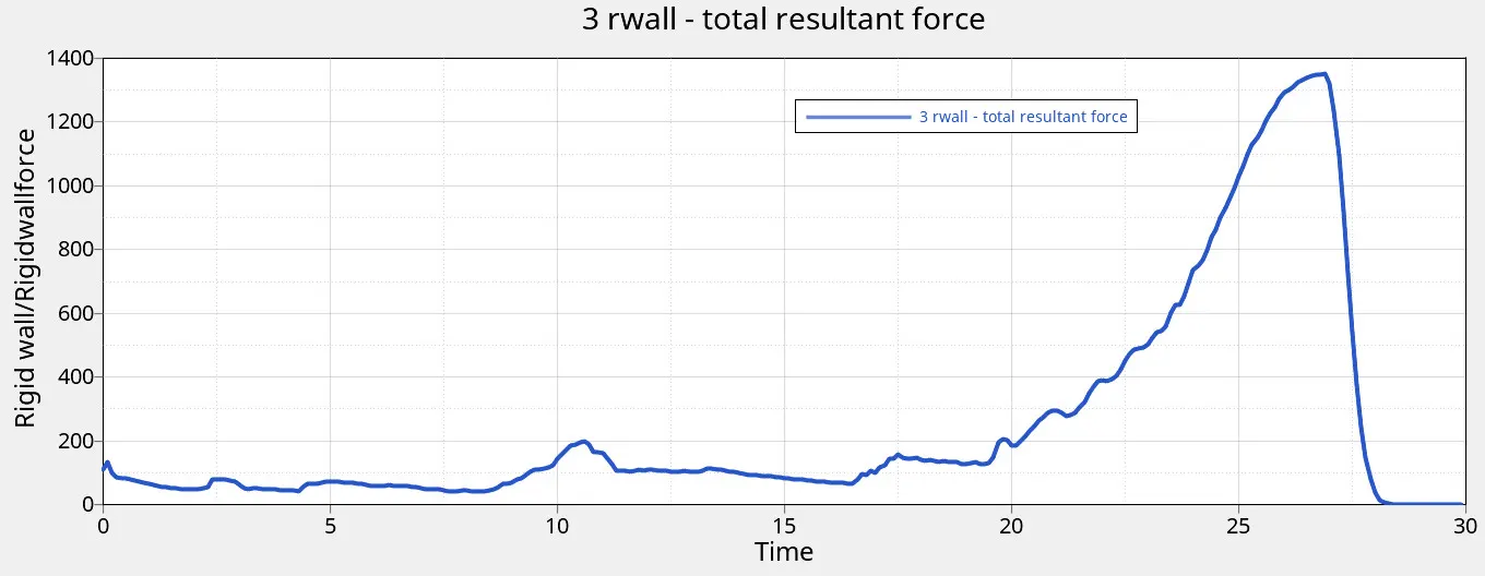
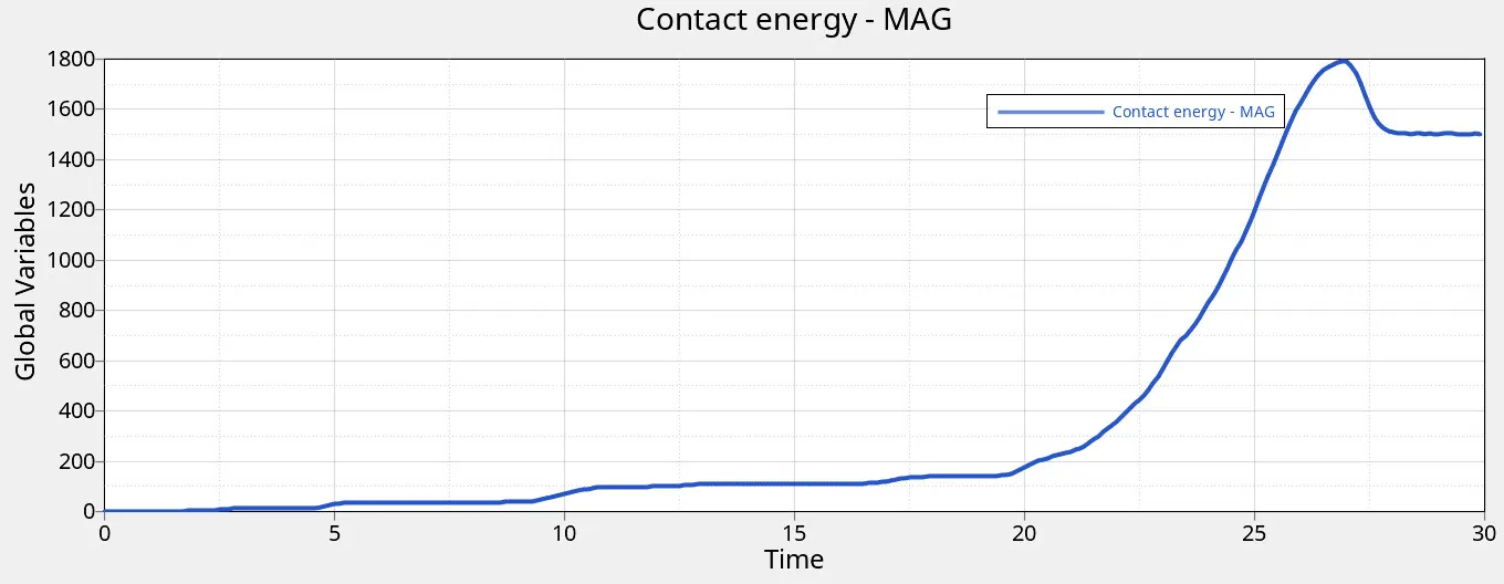
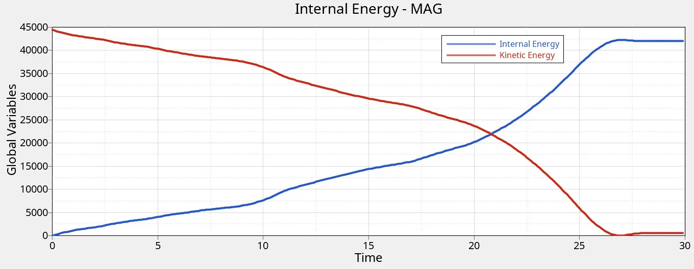
Fig 23 Rigid wall force, Contact energy, internal energy, and kinetic energy
The maximum rigid wall total resultant force is found to be 1203.61 KN
The maximum contact energy is found to be 1557.30 J
The maximum internal energy and kinetic energy are found to be 42006 J & 44400 J respectively.
Case 6: Create a new notch with nodes only from opposing 2 faces and run
In this case, the notch is created on the opposing faces of the crush tube model from previous case, while other parameters were kept constant.
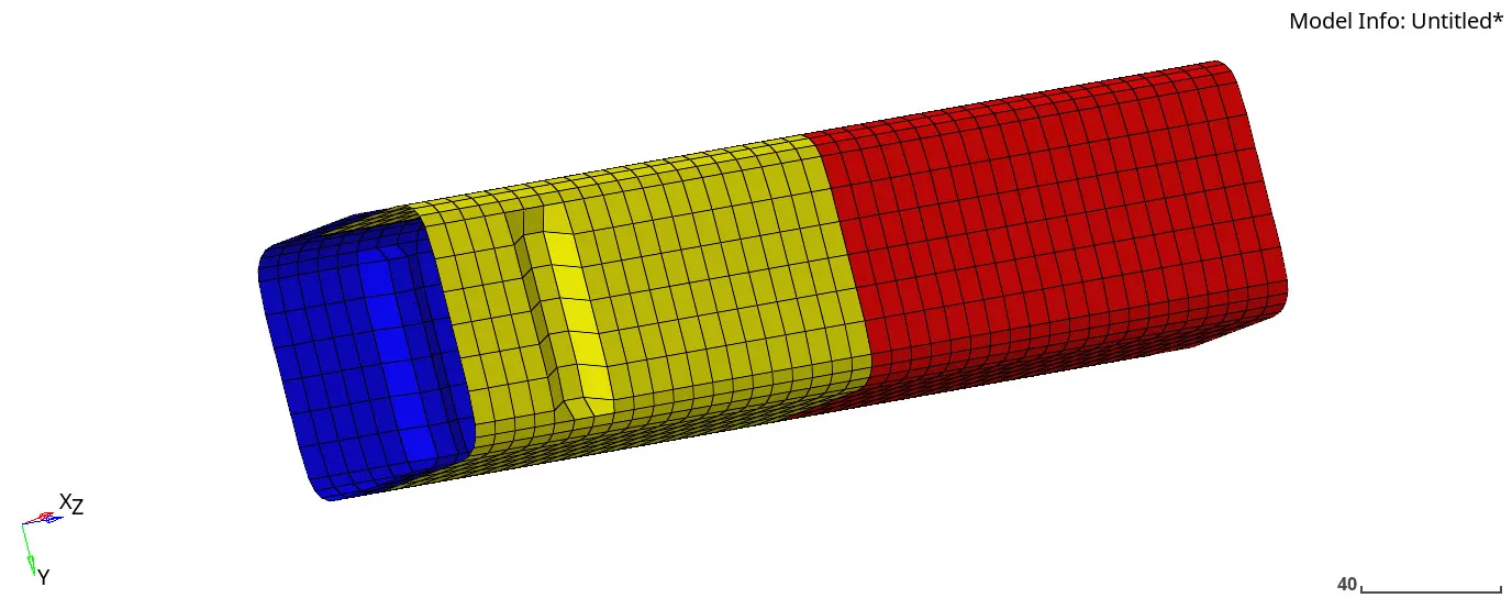
Fig 24 Crash tube with notch in opposing faces

Fig 25 Result checking
The energy error is -3.2%, well within the limits for QEPH elements. Hence, it is good to go for further analysis.
The maximum amount of Von-Misses stress is found to be 6.535e-1 KN/ mm².
The maximum amount of plastic strain is found to be 0.7253.
To rigid wall forces, contact forces and internal energies, open Crash_tubeT01 file in hypergraph 2D window.
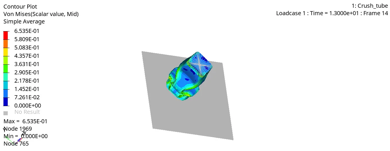
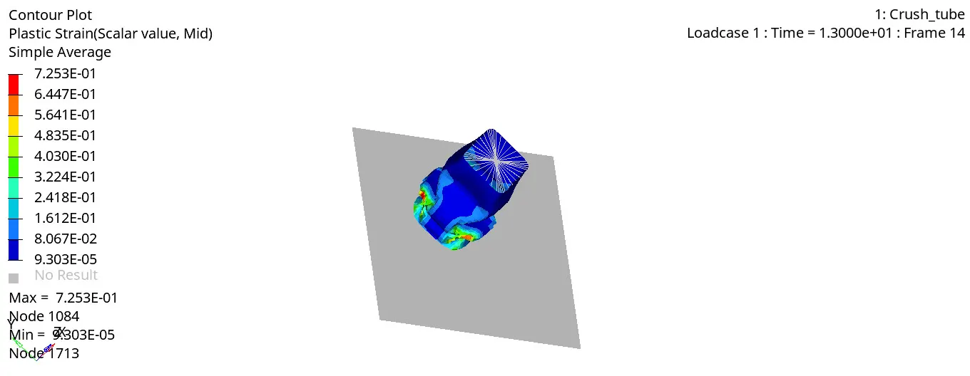
Fig 26 Von Misses and plastic strain simulation
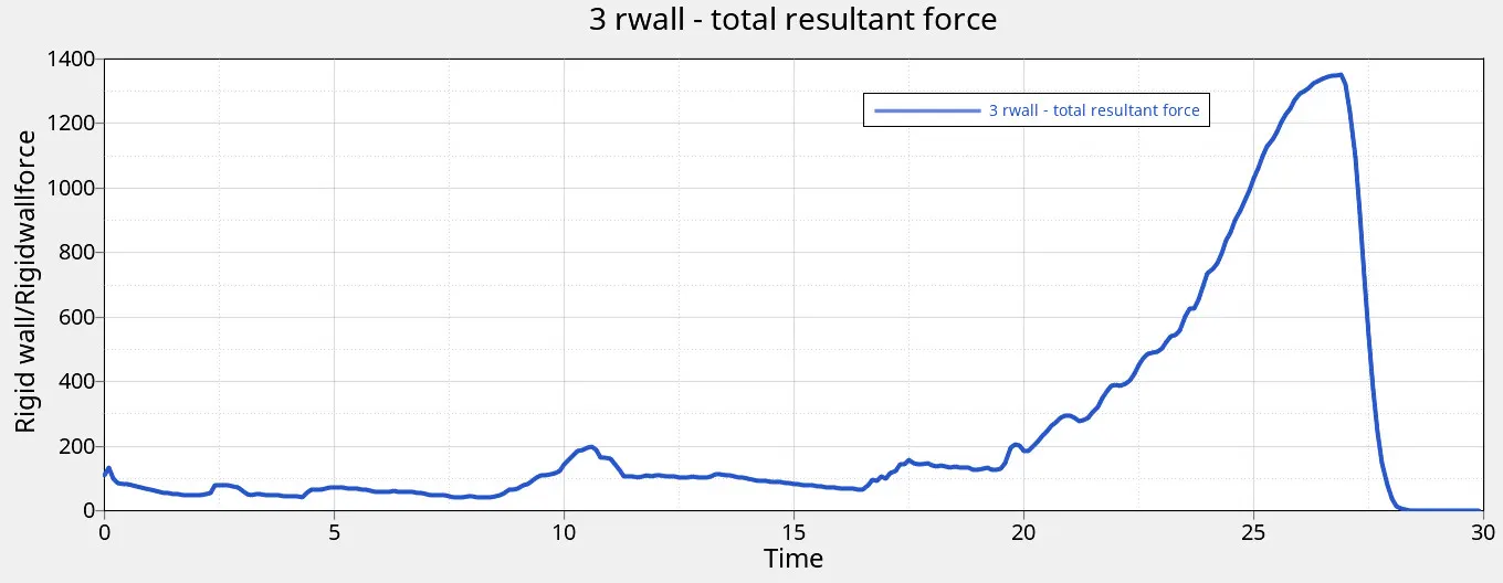
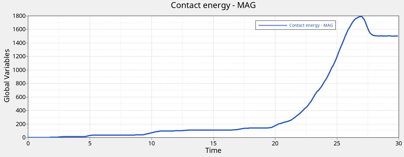
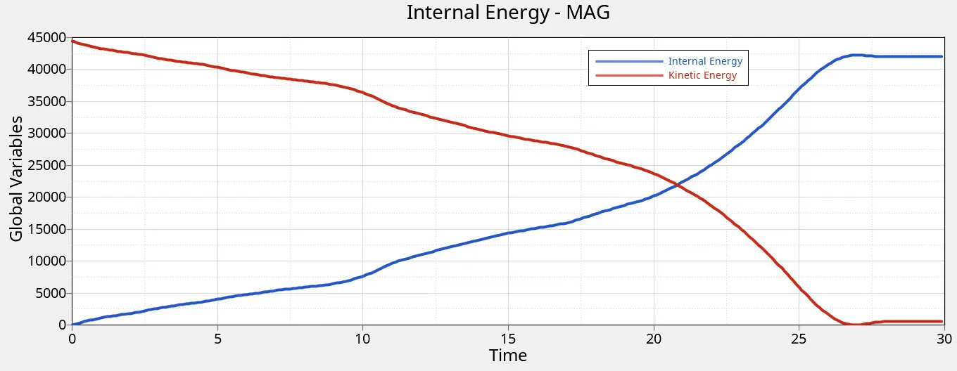
Fig 24 Rigid wall force, Contact energy, internal energy, and kinetic energy
The maximum rigid wall total resultant force is found to be 1350.73 KN
The maximum contact energy is found to be 1791.309 J
The maximum internal energy and kinetic energy are found to be 42086 J & 44400 J respectively.
Results:
In this assignment, interface types penalty method is used for contact (master/slave) treatment. The interface parameters plays a important role in determining the behaviour of the model under load case. In this work, different types of contacts are used to analyse the simulations of crash tube. The following results obtained as follows:
| Case type | Interface Parameters | Number of cycle | Energy error | Mass error | Maximum Von-Misses stress (GPa) | Maximum Plastic strain | Rigid wall force (N) | Contact energy (J) | Internal energy (J) | Kinetic energy (J) |
| case1 | No change | 83691 | -3.80% | 0 | 0.6964 | 0.7238 | 1340.659 | 2031.59 | 42269 | 44400 |
| case2 | Inacti = 6 | 83691 | -3.80% | 0 | 0.6964 | 4.151 | 1340.659 | 2031.59 | 42269 | 44400 |
| case3 | Add TYPE 11 Contact | 84537 | -0.60% | 0 | 0.7138 | 1.44 | 1454.17 | 2031.59 | 43581 | 44400 |
| case4 | Removing notches and BCS card | 77668 | -3% | 0 | 0.4566 | 1.366 | 1203.61 | 1557.3 | 43594 | 44400 |
| case5 | Creating middle notch | 87864 | -3.40% | 0 | 0.6299 | 1.123 | 1203.61 | 1557.3 | 42006 | 44400 |
| case6 | Creating notches in opposite faces | 77396 | -3.20% | 0 | 0.6535 | 0.7253 | 1350.73 | 1791.309 | 42086 | 44400 |