Week 3
Mid surfacing and meshing an Automotive Hood with quality criteria and thickness
AIM
To create a mesh with the given quality criteria and make sure the component is free from geometrical errors
Steps to be followed
- Perform a geometrical check
- Extraction of mid surface
- Assigning quality criteria
- Creating mesh
- Adding thickness to the meshed element
- learning outcomes
- result
MODEL
The model given is HOOD or Bonnet of the CAR
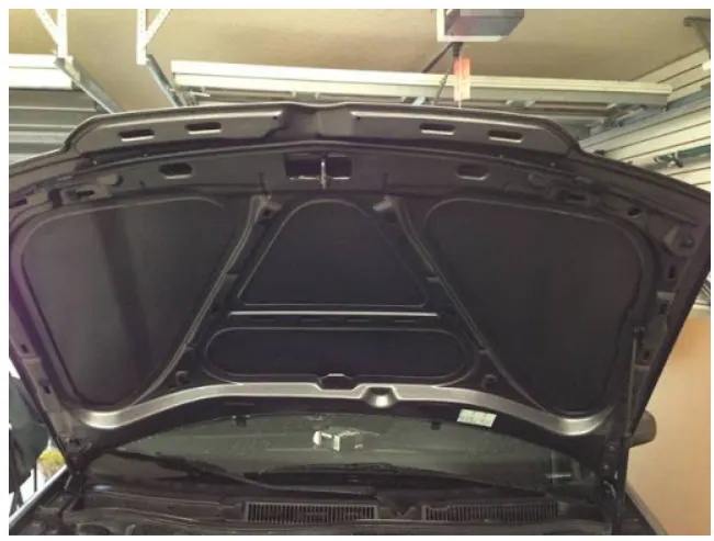
Bonnet of a car generally covers the engine compartment and other accessories like battery,radiator,electrical components etc.
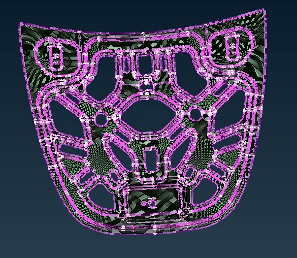
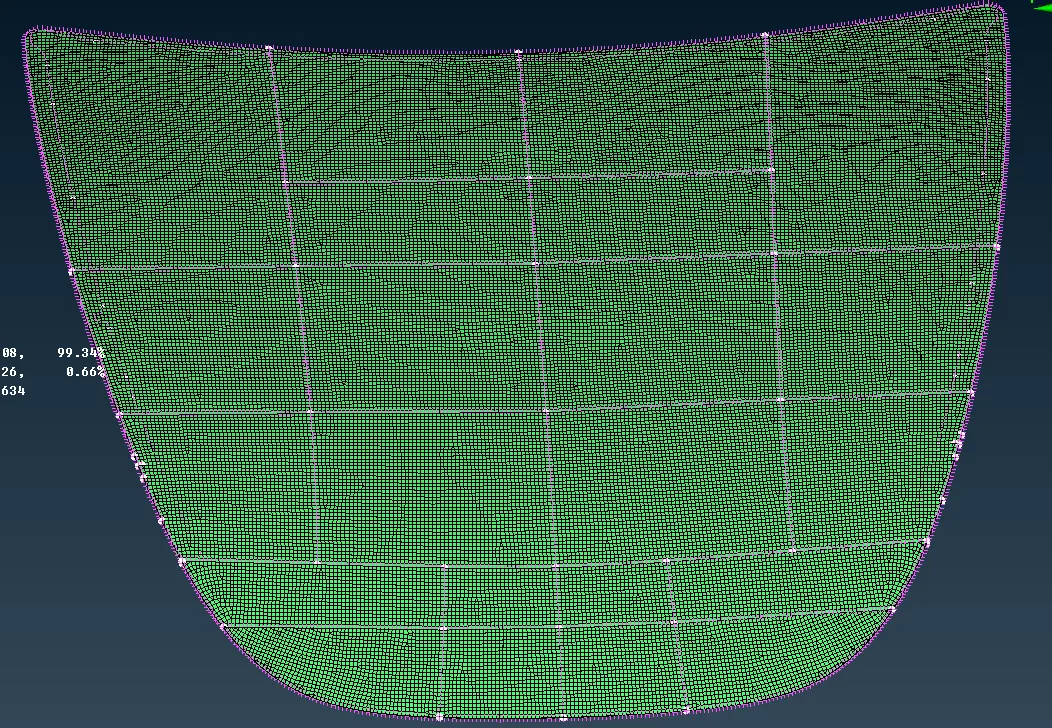
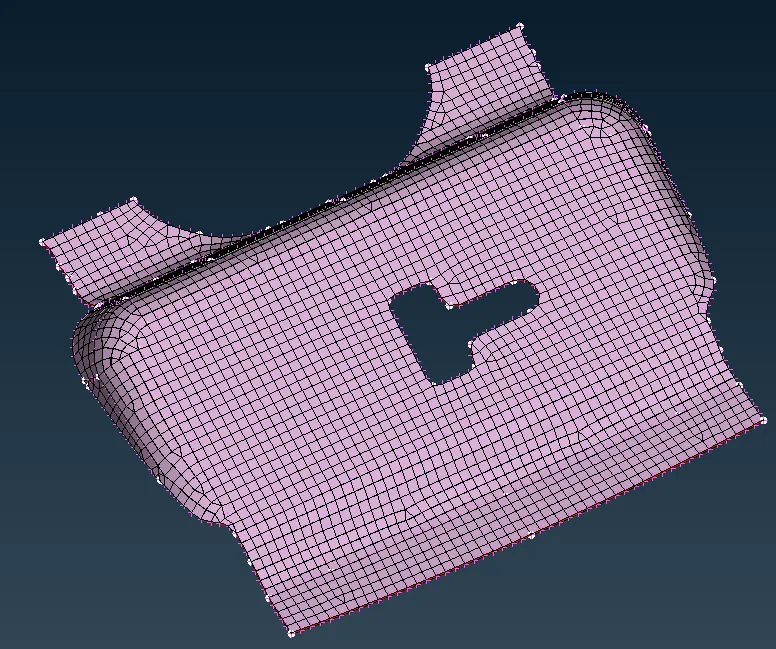
The component assigned to us is further classified into Outer hood, Inner hood , Hinge reinfocement, Latch reinfocement
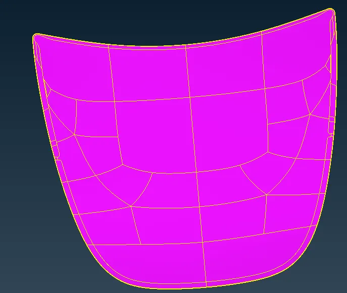
Outer hood
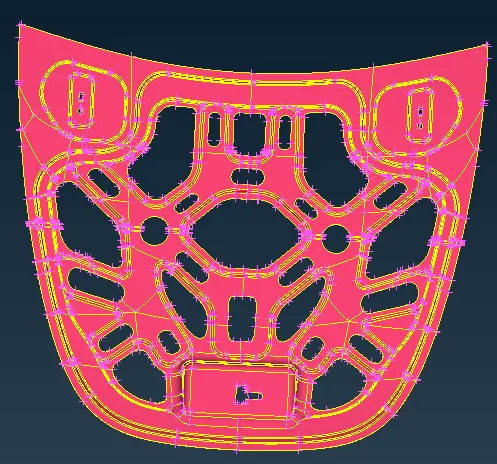
Inner hood
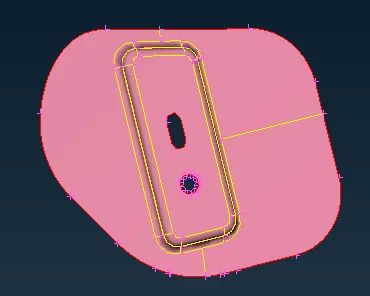
Hinge
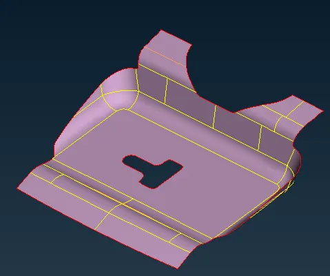
Latch
Performing Geometry checks
As soon as we open the file,we need to switch to ENT(Entity) mode. The component in ANSA should follow particular colour pattern throughout. It should be either gray or yellow colour. In ANSA grey means positive and yellow means negative if two colours found on same portion results may vary. The entity mode can be seen in drawing styles. always prefer grey colour
Also need to check with PID mode. In PID mode whole component should have same colour.
In order to check the topology first we have to check the surfaces stiched properly or not for this we have to open Checks manager . In checks manager we have to check first geometry by clicking the execute checks for the errors in the model. list of errors are given we need to select all the errors and fix them automatically. most common issues are Needle faces, Unchecked faces and Triple con issues. sometimes automatically we cannot fix the issue then we need to fix the error manually.
In ANSA surfaces are connected by CONS. Yellow color running onn the surface is double con, Red color running on the surafce is single con,blue cyan color is represented as triple con.
Cross hatches should be given to the component before Mid surface extraction we should click om cons for mid surface extraction
Isolate the component with boliean operations and Lock views
Thickness of the component should be measured through nodes before mid surface extraction. In ANSA thickness is measured in mm . In checking features Auxlaries-FINE option will help in refining as actual geometry.
Extraction of Mid surface
Now we will disintegrate the model 3D to 2D which is called MID-surfacing in ANSA
Manual mid surfacing
Faces-offset-faces
and then select one surface using cross hatches not by using cons because cons may select other attached ones and middle click. then a visible arrow may be observed arrow opposite to the selected surface. offset value should be half of the thickness value. negative sign should be given for grey surface positive value for yellow surafce
for identical features component mid surfaces can be transformed to other surfaces
Utilities-cut plane-Transform-copy-entities.
set separate PID(property id ) for the mid surface after this topo the entire component
Automatic mid surface generation is also possible but in automatic mid surafce generation parent surface will be gone. child surface is noting but mid surface. before going to meshing we need to again check for geometry in checks manager
Assigning quality criteria
Quality criteria should be assigned for the mesh before starting the mesh and mesh parameters also needed to assigned
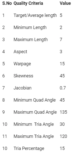
perimeter element value should be decided before starting the mesh Perimeters-length-perimeter
Even after changing the perimeter length we need check the distance between the hotpoints .If their is any inconsistency in the component we need to delete or rearange the hotpoints accoring to the length decided.
We also need to make the edge of the hole parallel to closest peimeter. perimeters-slide. once slide command is completed we need to mark the holes.
All the holes should have even number of nodes.
Fn+F11 is short cut key for quality criteria tab.
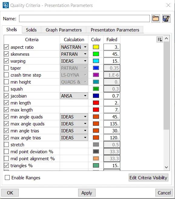
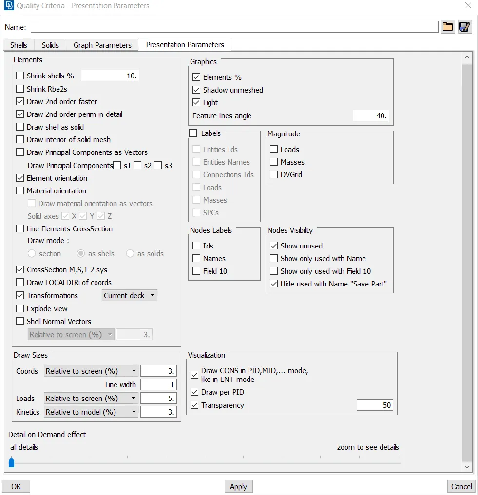
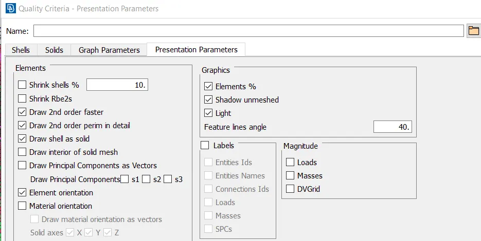
persentation parameters should be modified - element percentage should be enabled and details on demand should be modified.
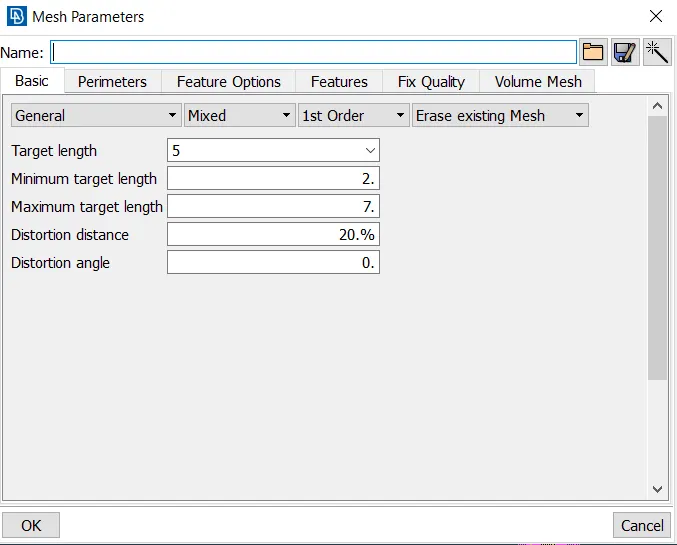
mesh parameters should be modified rhese are the basic parameters we need to set before meshing type of mesh , type of element, maximum length, minimum length order of mesh
Creating Mesh
All the meshing activity need to be done on Mid surface only. i used mesh generation-best mesh-select the area then the mesh is generated. to check the quality of the mesh switch to hidden mode. first i meshed critical ones and moved to eaiser ones. in the component critical areas are features,Holes,flat areas. when we switch to hidden mode some of the elements may fail the quality criteria. to resolve this issues their are some options in ANSA Like PASTE, SPLIT-EDGES-SHELLS , Reconstruction ,Smooth are used mostly. and also i deleted some lines on the surface of component which are very close to each other by measuring distance between those lines. distance between lines should satisfy minimum and maximum target length.
Adding thickness to the meshed component
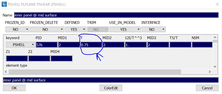
The mesh should be given thickness in property ID and then switch ON Draw shell as solid
Learning outcomes
- Geometry clean up
- Topological correcting
- Creating mid surface
- Creating Mesh
- Correction of mesh errors
- Adding thickness to mesh
Result
- A proper Mesh is created with no errors and mid surfacing of Automotive Hood component along with quality criteria.