Week 2 Railwheel and Track
OBJECTIVE: The project's objective is to perform a static structural analysis on Railwheel and track and compare Total Deformation, Equivalent Stress, and life under different loading conditions. Also, implement user-defined results and compare the total deformation with the inbuilt result by ANSYS.
Case 1: Multiply the bearing load by 5 times and compare the results with the load of 100000 N.Compare the Total Deformation, Equivalent stress, and the life under both the loads
Case 2: Implement a User-defined result and calculate the Total Deformation from this result and check if it is the same as that obtained by the inbuilt result by ANSYS for a load of 100000 N.
STEPS FOR PERFORMING ANALYSIS:
1. Open ANSYS workbench.
2. Select the static structural module.
3. Select the proper Engineering data card.
4. Import geometry.
5. Open Mechanical model.
6. Give proper connections (contacts and joints).
7. Generate mesh.
8. Set Analysis Setting as per given.
9. Insert output request
10. Analyze Result.
ANALYSIS SETUP:
GEOMETRY
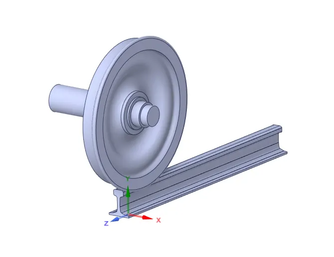
Import given model in ANSYS Workbench for static structural analysis. The Railwheel model consists of the track, wheel and Shaft.
MESHED MODEL:
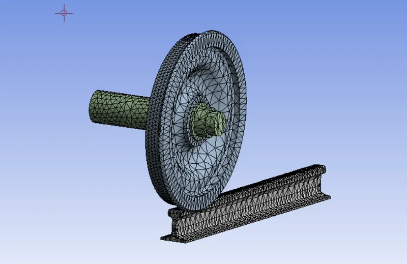
We meshed the model with an element size of 0.75mm.
Details:
- Global Element Size = 30 mm
- Face Element Size = 20 mm
- No. of Nodes = 29508
- Element = 15472
MATERIAL PROPERTIES:
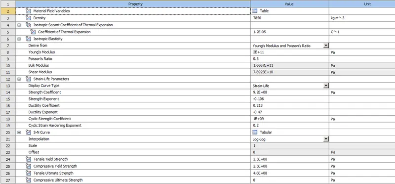
Material is the same for both cases.
- Structural Steel
PROCEDURE FOR ALL CASE:
1. Import model in ANSYS Workbench.
2. Assign material properties.
3. Open the mechanical module were we going to perform analysis.
4. Meshed the model with desired element size.
5. Now after meshing, From Project Tree, select "Connections" and create "Contact".
- Contacts:
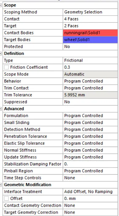
- First contact between Wheel and the Track.
The contact type is Frictional with the frictional coeff of 0.3.
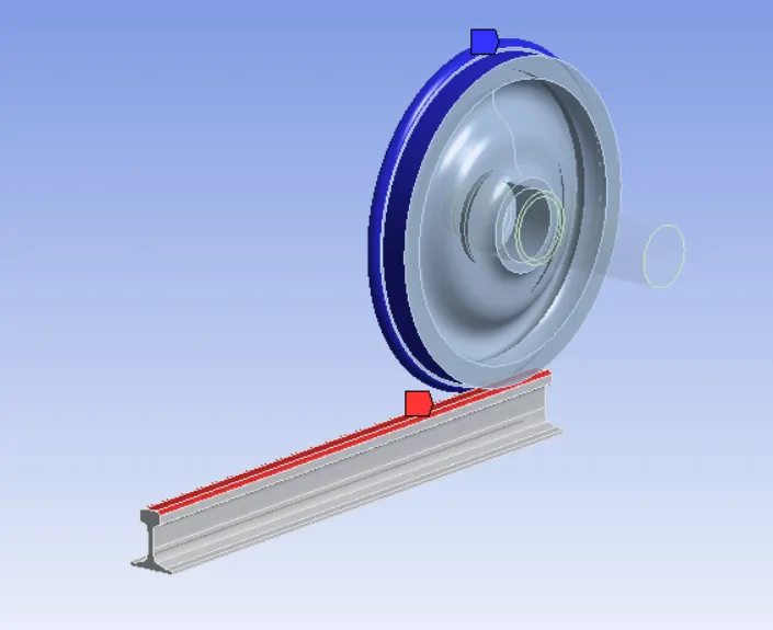
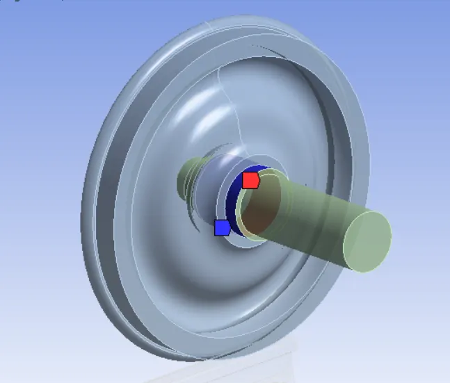
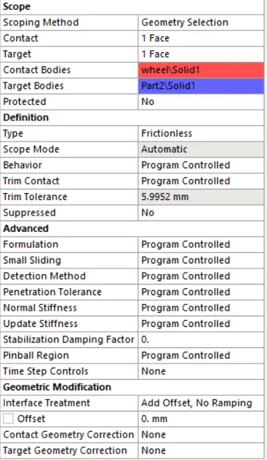
2. Second contact between wheel and shaft.
The contact type is Frictionless.
7. JOINTS:
After the creation of Contact between gears now create joints.
Connection Type = Body-Ground for all joint
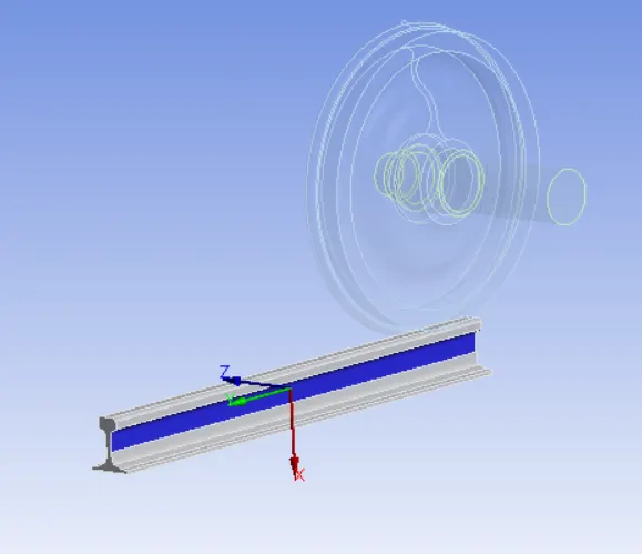
- Fixed joint for the track to restrict the motion.
Select Both sides of the track.
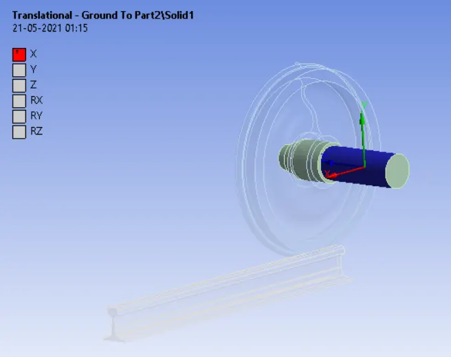
2. Translational joint between shaft and wheel which allows the wheel to translate along the track.
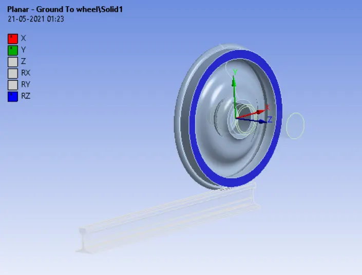
3.Planar joint for the wheel. The planar joint element is a two-node element that has two relative displacement degrees of freedom and one relative rotational degree of freedom. All other relative degrees of freedom are fixed.
8. BOUNDARY CONDITIONS:
Now let's define the Boundary condition.
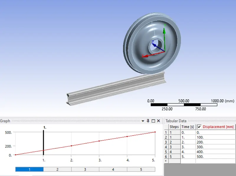
- Here we are going to look at contact faces and stress developed during translation of wheel for 500mm in 5 steps.
- In an analysis for 1 step only on large deflection, leave the setting as it is and for the rest step 4 (2-5) give value as shown in the figure.
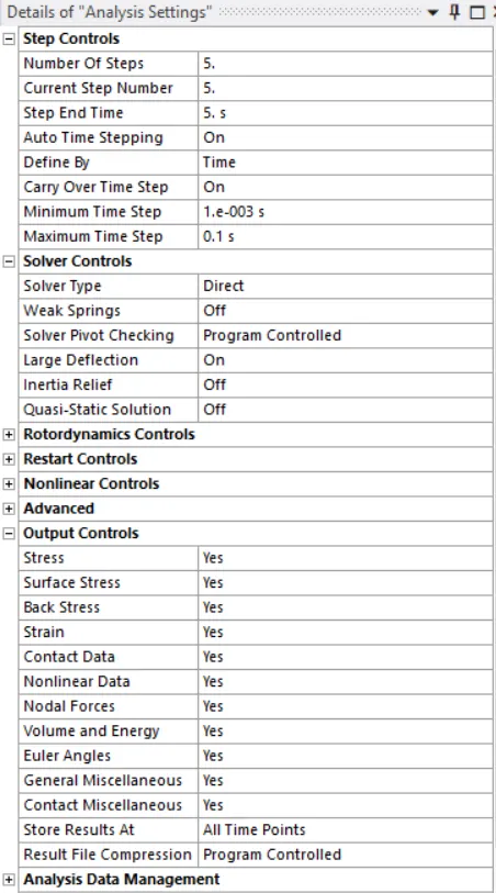
Fig. Analysis Setting
- Other boundary conditions are given below
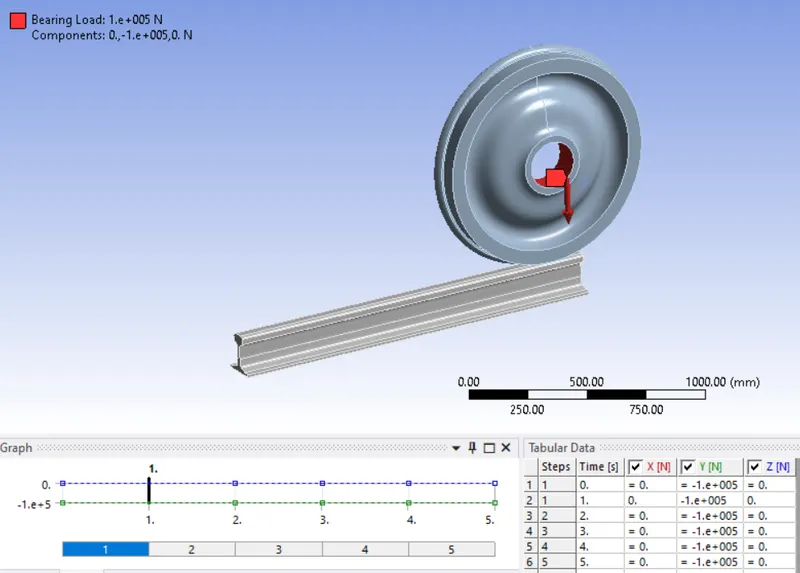
1. Bearing Load:
Force = 1e+05N in Y direction for CASE 1(A)
Force = 5e+05N in Y direction for CASE 1(B)
Magnitude: Tabular data
2. Joint Load:
Type: Displacement in the X-direction.
Magnitude: Tabular data
9. SOLUTION:
- After giving proper Boundary conditions, create a solution for the output result.
1. Equivalent Stress (Von-misses) and Equivalent Elastic Strain for Wheel and complete model,
2. Total Deformation.
3. Fatigue tool for the factor of safety.
4. Contact tool for stress and pressure between
- Wheel and track.
- Shaft and wheel.
5. Force Reaction for the wheel.
6. User-defined result.
RESULT:
CASE 1:
(A). Load 100000 N:
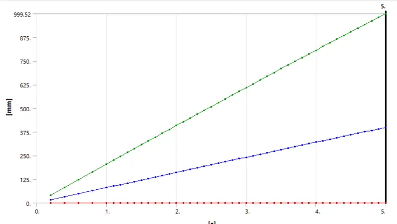
1. Total Deformation
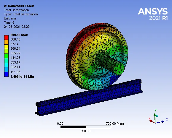
Maximum Deformation = 999.52 mm
- Deformation Contours:
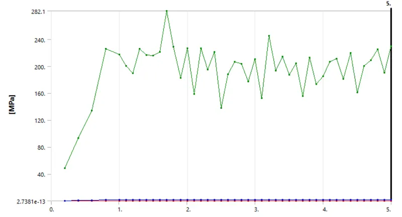
2. Equivalent Von-Misses Stress:
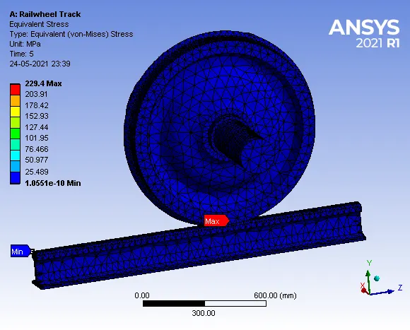
Maximum Stress = 229.4 MPa
- Stress Contours:
3. Equivalent von-misses strain:
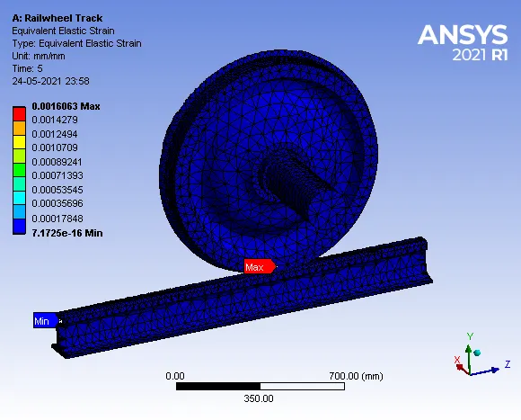
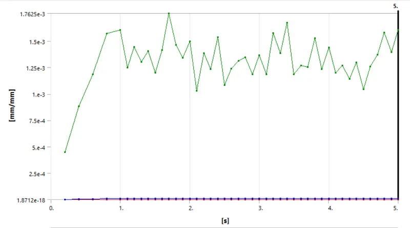
Maximum Strain = 0.0016063 mm/mm
- Strain Contours
4. fatigue Life:
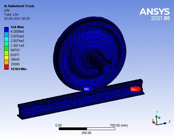
(B). Load 500000N:
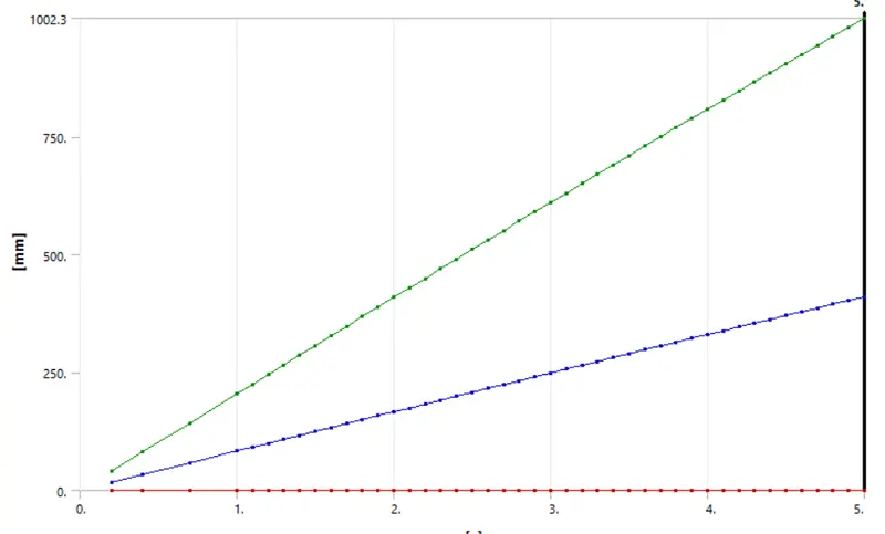
1. Total Deformation:
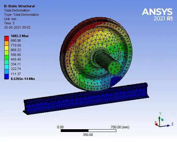
Maximum Deformation = 1002.3 mm
- Deformation Contours:
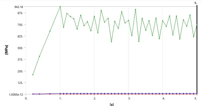
2. Equivalent Von-misses stress:
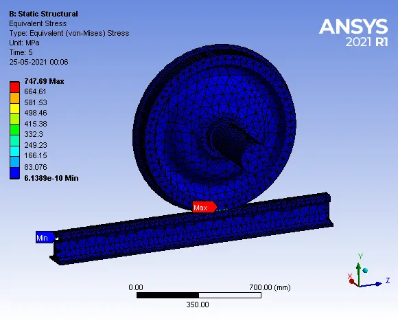
Maximum Stress = 747.69 MPa
- Stress Contours:
3. Equivalent von-misses strain:
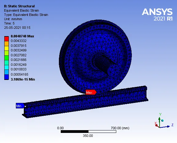
Maximum Strain = 0.0048748 mm/mm
- Strain Contours:
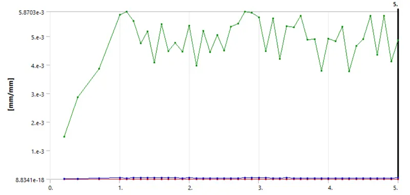
4. fatigue Life:
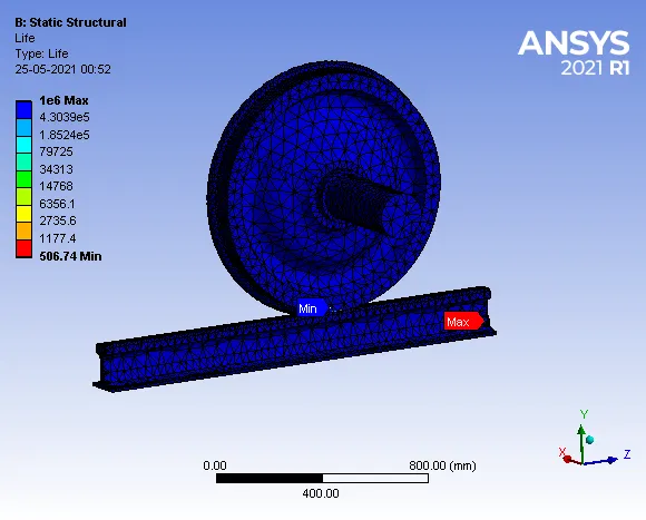
Minimum = 506.74
COMPARISON:
| S No. | LOAD (N) | Maximum Deformation | Maximum Stress | Maximum Strain |
Fatigue Life (Max) |
Fatigue Life (Min) |
| CASE A | 100000N | 999.52mm | 229.4 MPa | 0.0016063 mm/mm | 1e+06 | 15764 |
| CASE B | 500000N | 1002.3 mm | 747.69 MPa | 0.0048748 mm/mm | 1e+06 | 506.74 |
From the above table, we can see that for a load of 500000 N we get equivalent stress of 747.69 MPa which much larger compared to the load of 100000 N which is only 229.4 MPa. Also, the Minimum fatigue life reduced in case of an increased load in comparison to 100000 N load.
CASE 2: Total Deformation with the user-defined result and inbuilt result in ANSYS.
1. Inbuilt Result for Total Deformation:
Maximum Deformation = 999.52 mm
2. User Defined Result for Total Deformation:
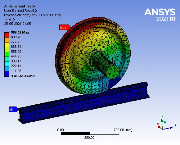
Maximum Deformation = 999.52mm
For Case 2 we get the same Total Deformation with an inbuilt result and user-defined result and the expression used for the user-defined result is (sqrt(Ux^2 + Uy^2 + Yz^2)).