Week 2 Railwheel and Track
we are performing static analysis to check how the bearing load effect the results of Rail wheel and track analysis.
1. To start the analysis. We have drawn the static structure analysis into the work place.
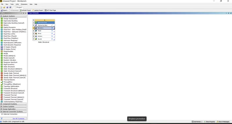
2. Double click on the engineering materials and add structural steel.
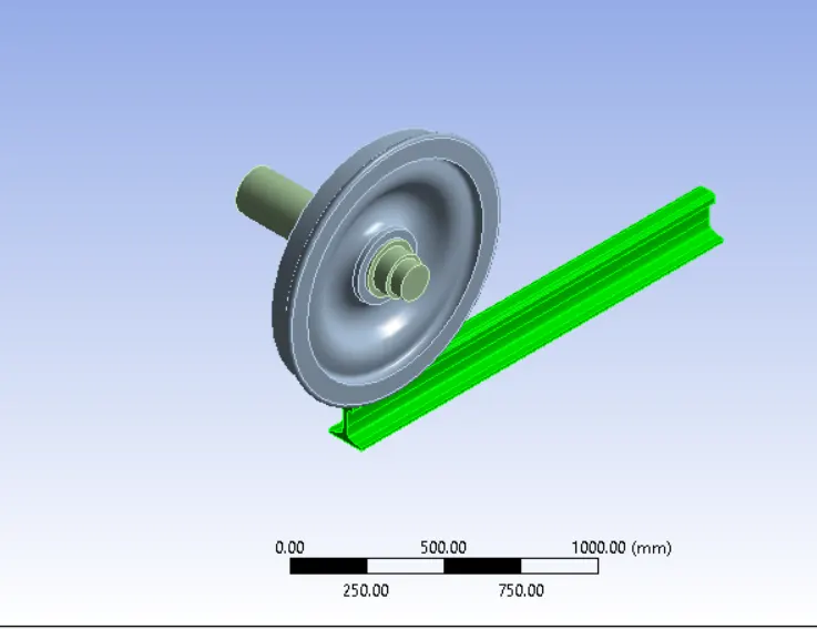
3. Now double on the geometry and import the model. Now check the geometry. We found 3 different parts are shaft, wheel and track.
4. Open the model by double click on the model. After opening the model interface just check weather our model loaded or not.
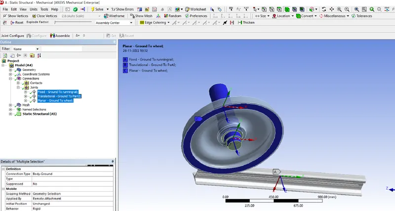
5. Go to connection and give the connection as required shown below.
1. Give the fixed support to the track.
2. give the planner connection to the wheel so, it can move in single plane.
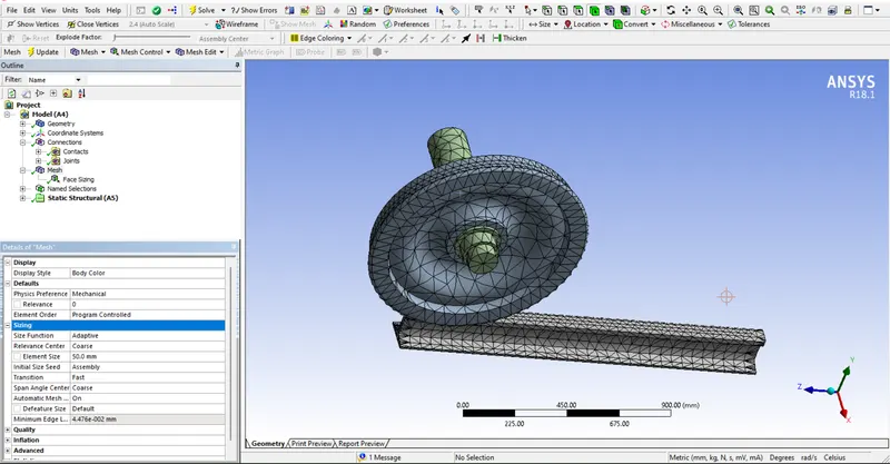
6. Now go to mesh setting. put default size as 50 mm. and generate the meshing.
7. To get accurate results we can see decrease the mesh size to 35 mm at the meeting parts.
8. After completing the meshing. Go to analysis setting now change the steps to 6.
9. Now select the step 1 make the changes as below.
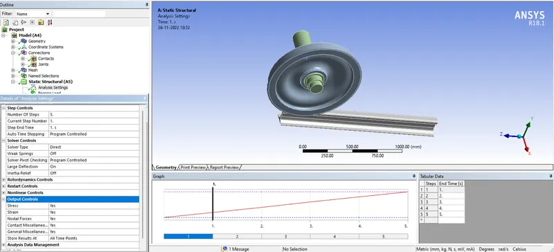
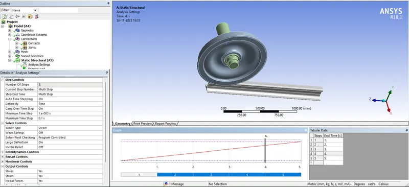
and reamaining step use below changes by selecting 2 to 5 steps.
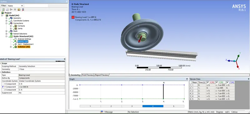
10. Create the bearing at the shaft and wheel connection. Take the bearing load of 100000 N.
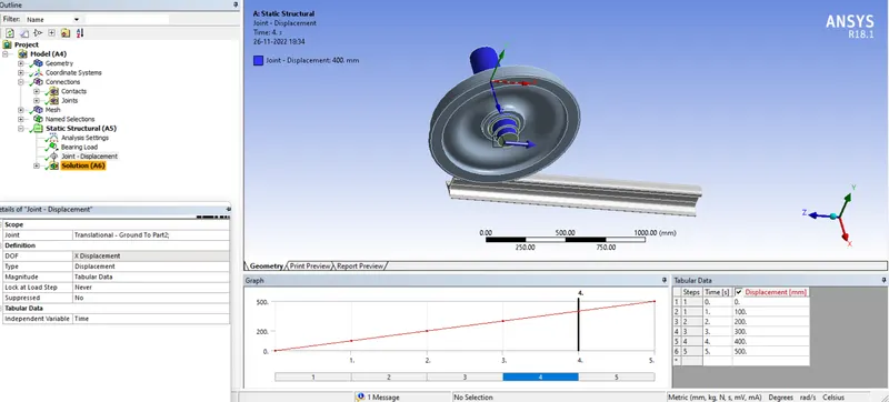
and create the joint displacement to check the analysis.
11. Crete the solution set which we required to find, like stress and strain.
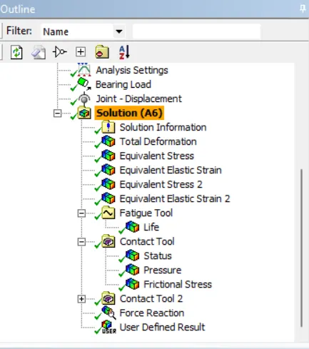
12. Create the user defined values to check the computer used same formulation.
Run the solution.
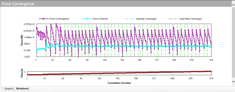
We can see the force convergence. The force convergence means we can plot force between the gears when meeting. We can see the how the force varies with the time in mating.
Here we can see stress and total deformation from the analysis.
Case 1:
We have to set the parameters to check the stress and strain values for two different loads. We use the 100000 N of load for actual analysis. And 500000 N load in parameter set.
Now check the terms which we want to check in the parameter set. I have selected the load and stress and total deformation.
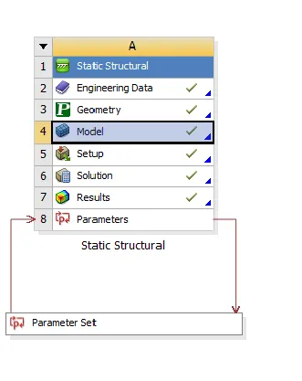
1. Now come to main interference of the ANSYS workbench. Double click on the parameter set.
2. Now give the load of 500k. update the design. It will run solution we can see different values for different loads.
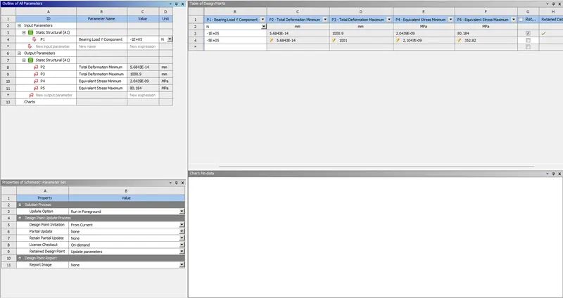
From the above observation for the load of 100k we got the stress values as below.
S. NO. Minimum stress (MPa) Maximum stress (MPa)
1 0.0249 80.184
And deformation values are-
S. NO. Minimum (mm) Maximum (mm)
1 5.589e-0.14 1000.9
From the above observation for the load of 100k we got the stress values as below.
S. NO. Minimum stress (MPa) Maximum stress (MPa)
1 0.02104 352.82
And deformation values are-
S. NO. Minimum (mm) Maximum (mm)
1 5.68e-0.14 1001
Case 2:
In user defined results I have used to check the formulation for total deformation.
In user defined I have selected the deformation in X, Y and Z direction. For that I have given output as Ux Uy and Uz.
We have values as below
Ux = 0.012706 mm
Uy = 500.92 mm
Uz = 1.6981 mm
The total deformation is sqrt (Ux^2+ Uy^2+ Uz^2).
from the conclusion that both has given same values.
both values are geting same.