Week 2 Railwheel and Track
Aim: To perform a static structural analysis on the Rail wheel and Track setup and
Objective:
Case 1: Compare the results with the bearing load of 100000 N & multiplying it by 5 times. Compare the Total Deformation, Equivalent stress, and the life under both the loads.
Case 2: Implement a User-defined result and calculate the Total Deformation from this result and check if it is the same as that obtained by the inbuilt result by ANSYS for a load of 100000 N.
Introduction:
A train wheel or rail wheel is a type of wheel specially designed for use on railway tracks. The wheel acts as a rolling component, typically pushed onto an axle and mounted directly on a railway carriage or locomotive, or indirectly on a bogie. The wheel is manufactured from steel.
Procedure:
- After opening Ansys Workbench, use static structural as the mode of analysis for simulation.
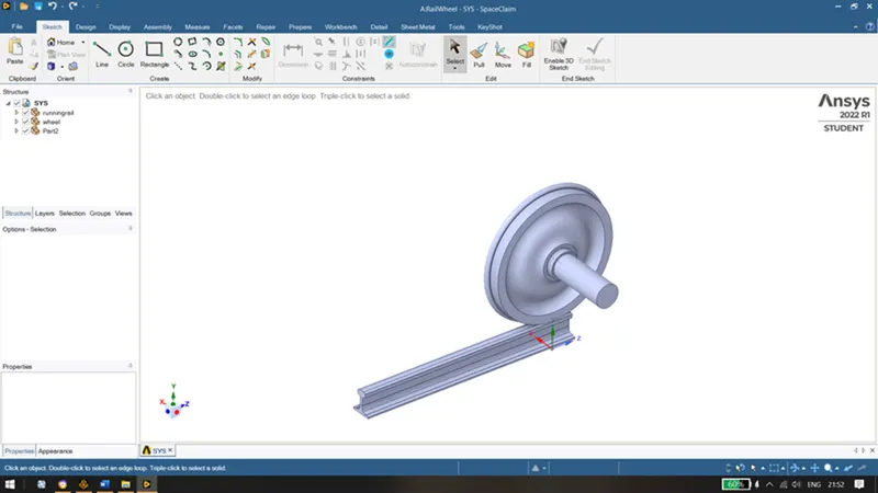
- After structural steel is used for both rail wheel and rail track, import the geometry given. Checking the geometry in the Ansys Spaceclaim for any abnormalities.
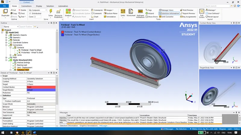
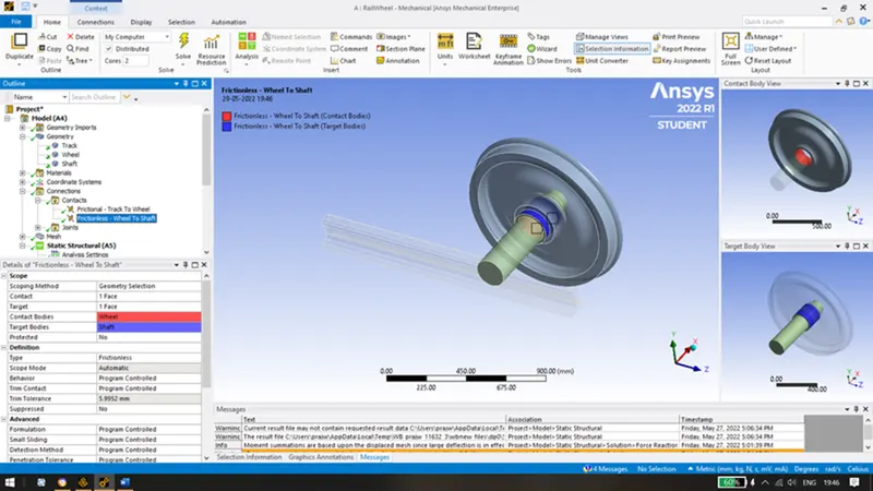
- Create contact points between the wheel and the track(Friction of 0.3); the wheel and the shaft(frictionless).
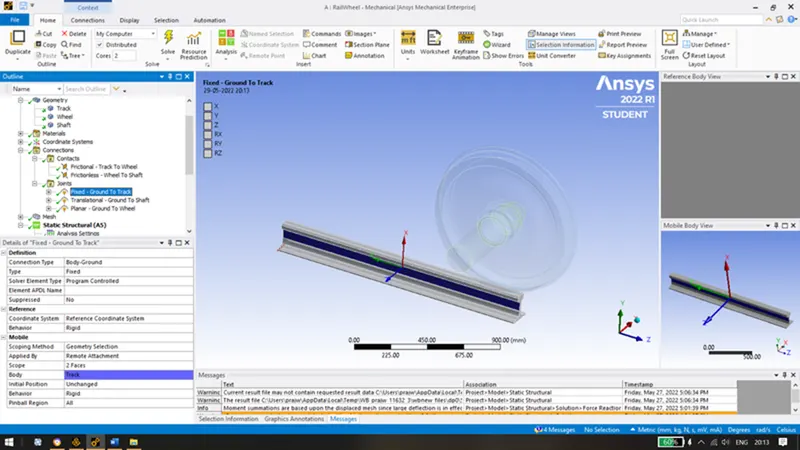
- Create joints such as fixed joint on the track, translation joint on the shaft so that it moves in a particular direction and planar joint on the wheel so that wheel moves in the given plane.
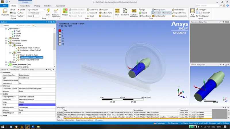
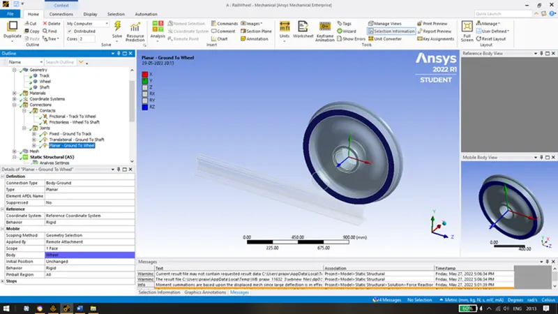
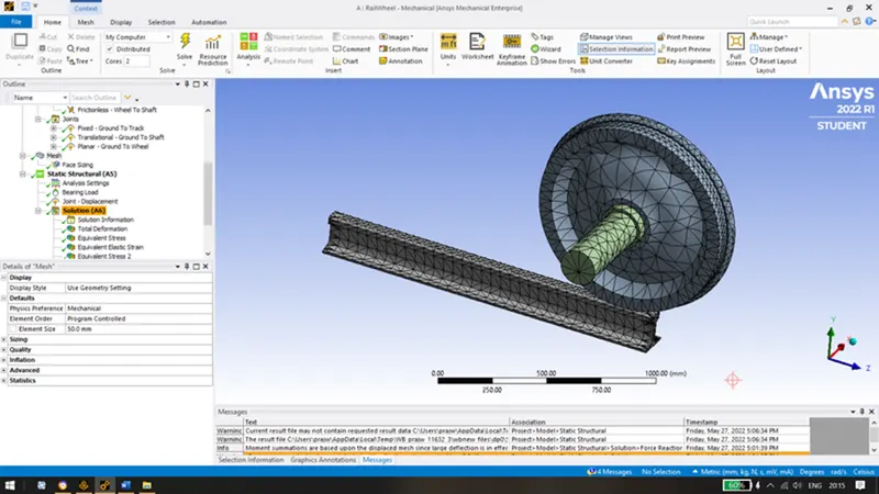
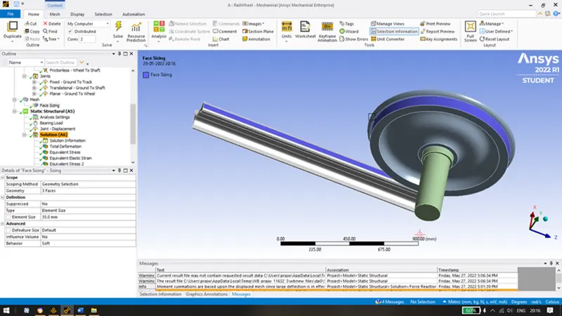
- Mesh the track, wheel and shaft with an element size of 50mm. And refine mesh on the faces which are coming in contact for our study using sizing of 35mm.
- Now in analysis settings keep no. of steps as 5 and turn on large deflection and force convergence; also apply a bearing load 100000N in negatuve Y direction with the following outputs as shown below:
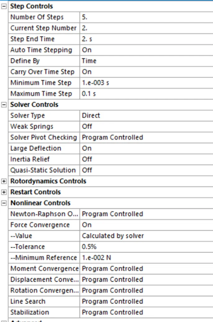
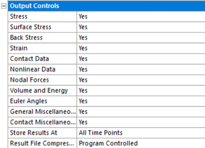
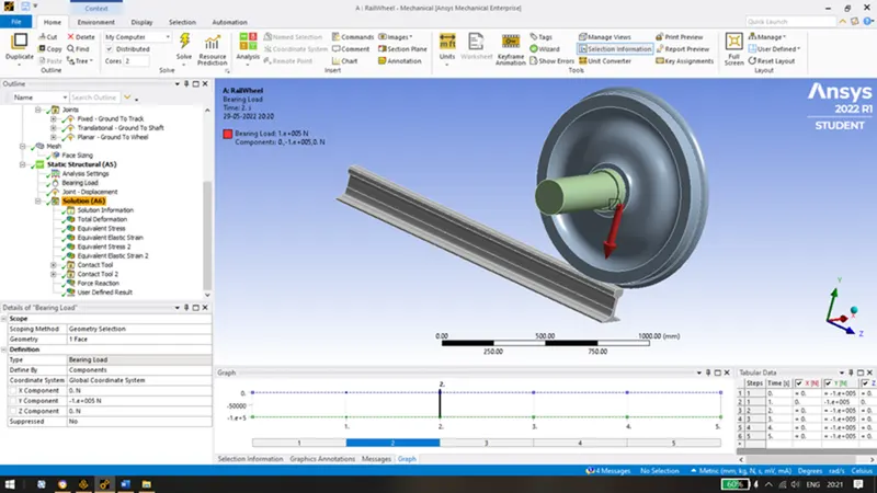
.
The displacement is in the x direction with 5 steps from 0mm to 500mm
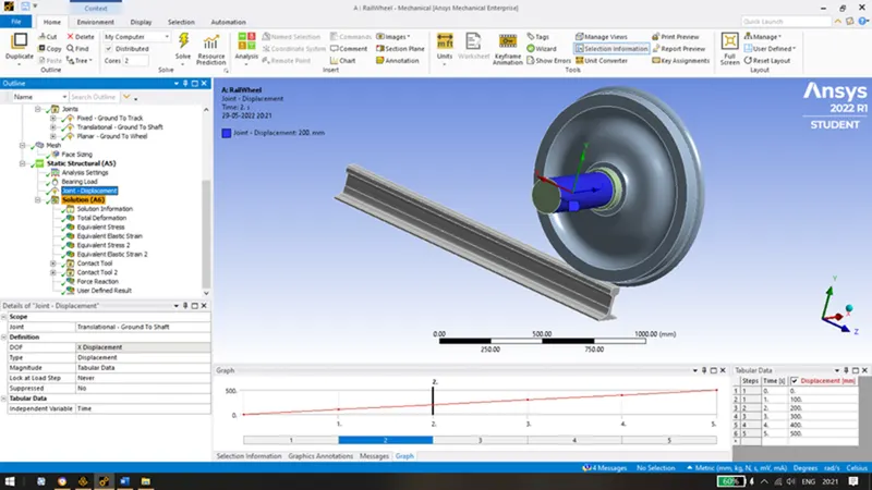
- Following Solutions have been obtained after running the simulation:
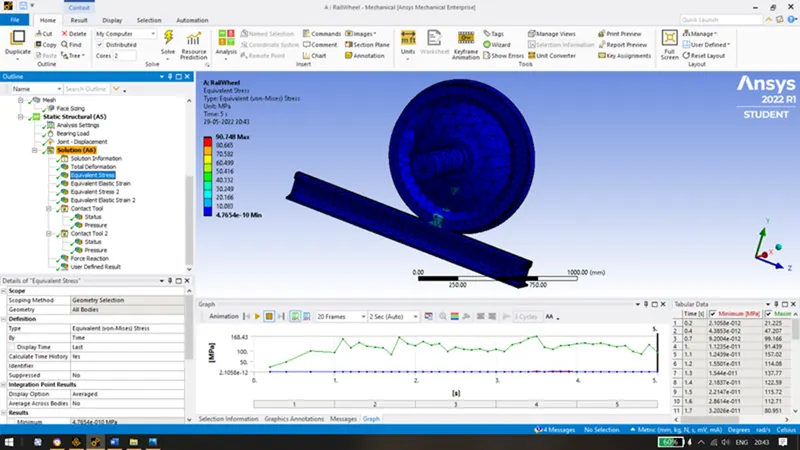
- A) For 100000N bearing load:
Max Stress of 90.748 MPa was obtained.
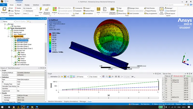
Total deformation of 1001.3 mm was obtained.
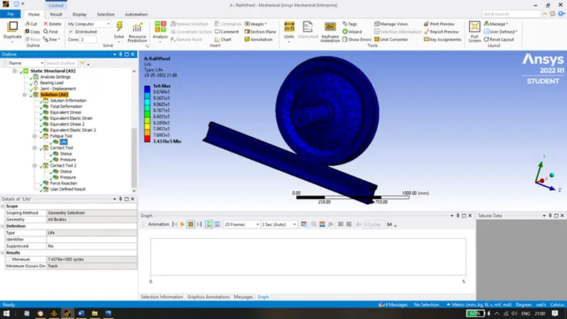
A minimum fatigue life of 743760 cycles is obtained.
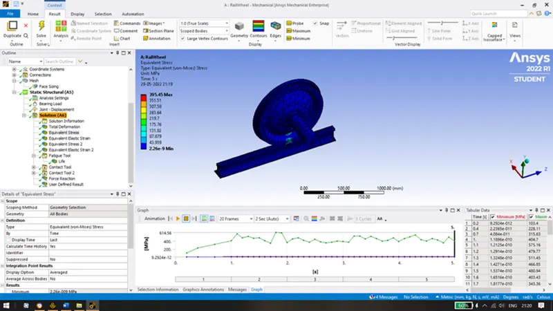
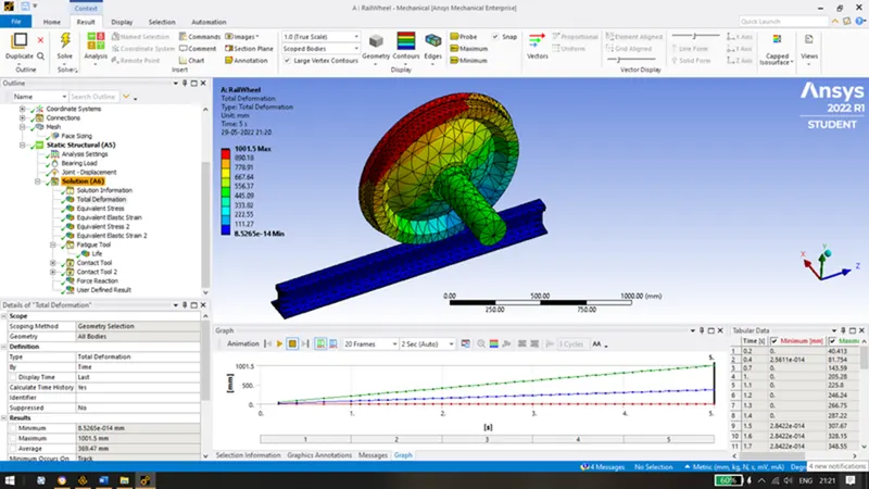
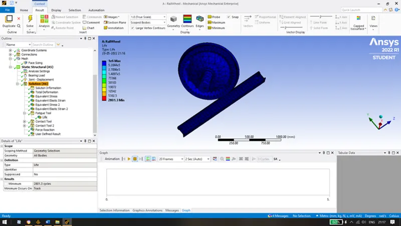
- B) Similarily, we run the simulation for 500000N bearing load.
Max Stress of 395.45 MPa was obtained.
Total deformation of 1001.5 mm was obtained.
A minimum fatigue life of 2801.3 cycles is obtained.
Case 2: For User Defined result, we manually enter the expression as sqrt(Ux^2 + Uy^2 + Uz^2) and selecting output as displacement where U is the displacement in a given direction.
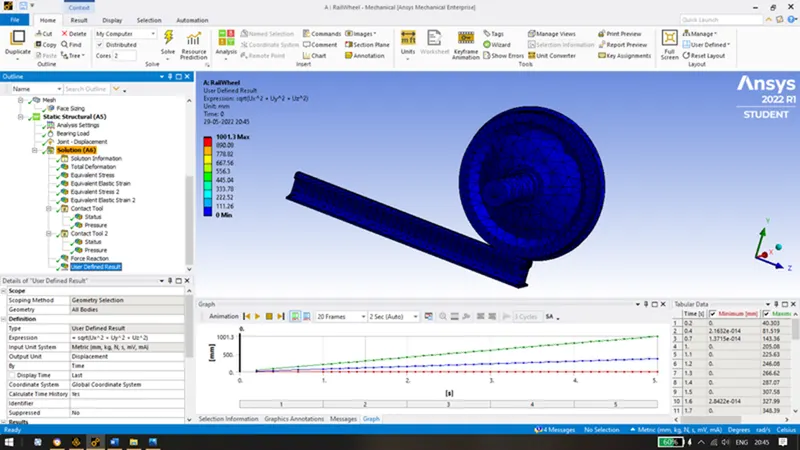
Now, let us compare with the solution generated by ansys i.e. the Total Deformation
Conclusion:
Case 1: We can see that when the bearing load is increased by 5 times, there is an increase in the max equivalent stress and the number of cycles is reduced by a very large number. But the deformation caused is almost negligible. The life cycle in the case 2 can be increased by improvising and the selecting of the material which has better properties than structural steel.

Case 2: From the above results, we can see that the result generated by ansys and the user defined result for 100000N bearing load with a displacement of 500mm are exactly same. Hence, we can manually use the values generated in the simulation and create an user defined result. The values generated can be seen in worksheet tab.