Week 2 Railwheel and Track
Question
Perform a static structural analysis on the Rail wheel and Track setup and
Case 1: Multiply the bearing load by 5 times and compare the results with the load of 100000 N (As done in week 2 video). Compare the Total Deformation, Equivalent stress and the life under both the loads
Case 2: Implement a User defined result and calculate the Total Deformation from this result and check if it is the same as that obtained by the inbuilt result by ANSYS for a load of 100000 N.
Analysis Systems
Static structural
Geometry
Ensure both wheel, shaft and track are assigned as structural steel
Materials
Structural steel
Model upload.
Upload the model in to the geometry and edit in the model state.
Change the material in the geometry to structural steel.
Contacts
Open the connections and contact and select both contact
And rename based on definition
Flip the contact
First contact with shaft and wheel and
Second contact with wheel and track
Wheel and track contact should be frictional and coefficient 0.3
Shaft and wheel contact should be frictionless
Joints
Make track as grounded from body grounds
Make wheel shaft as Translational joint
Make wheel as planar joint
Coordinate systems
Now check the axis of shaft is along with translational axis so change the coordinate system
Mesh
Insert the sizing for the mesh in surface of the track and wheel only
Analysis settings
Change the step as 5 and
Auto time stepping should be program controlled
Switch on large deflection
Solver type direct
All output control parameters should be yes
Nonlinear controls switch on force convergence as ON
Select all steps up to 5 and set auto time stepping as ON.
Defined by TIME
Carry over time step ON
Minimum time step should be 1e-3
Maximum time step should be 0.1s
Static structural
Insert joint load
Select Translational
DOF X displacement
Type displacement
Magnitude Tabular data
And input in the tabular data as 100, 200 to 500
Select bearing load on the inside surface of the wheel
Defined by component and select as Y component -1e5 for the first case and -5e5 for the five times case.
Solution
Inset the total deformation
Insert the von mises stress and
Insert von mises strain
Insert stress and strain again and select wheel body only
Insert contact tool twice and select only one on one item
First one for the shaft and wheel and second one for the wheel and track
From the contact tool insert pressure on both
Insert a probe and select force reaction and weak spring as boundary condition. Select geometry as wheel body
Insert a user defined result
Put RX in the expression area and select angle in the output unit.
Before the result please check the cores from the tools
Then just hit the solve button
Results
Case 1: Multiply the bearing load by 5 times and compare the results with the load of 100000 N (As done in week 2 video). Compare the Total Deformation, Equivalent stress and the life under both the loads
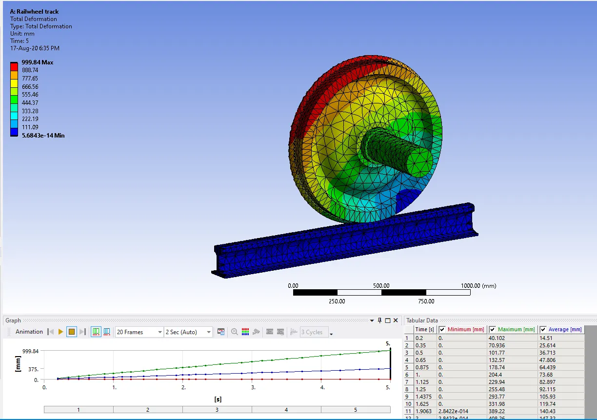
Total Deformation 10000 Bearing load
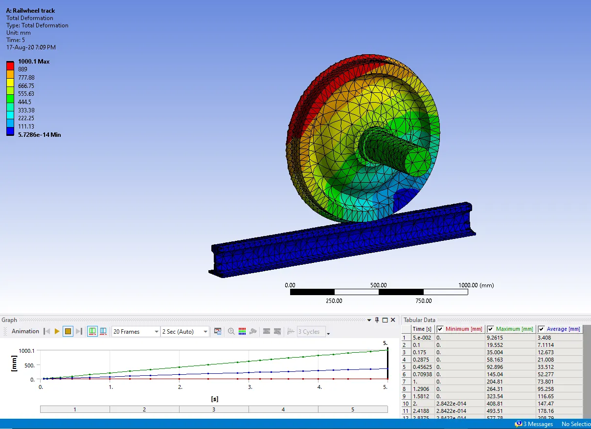
Total Deformation 50000 Bearing load
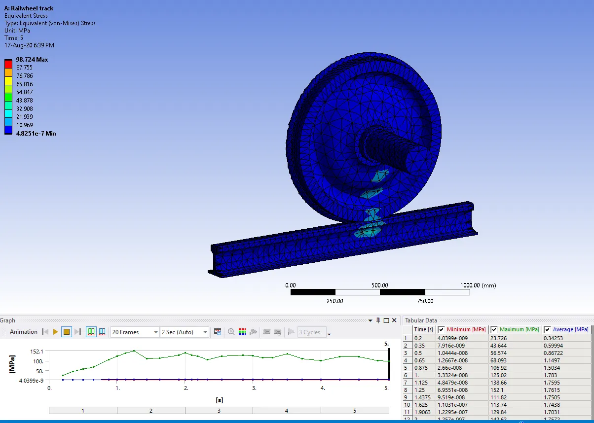
Equivalent stress at 10000 Bearing load
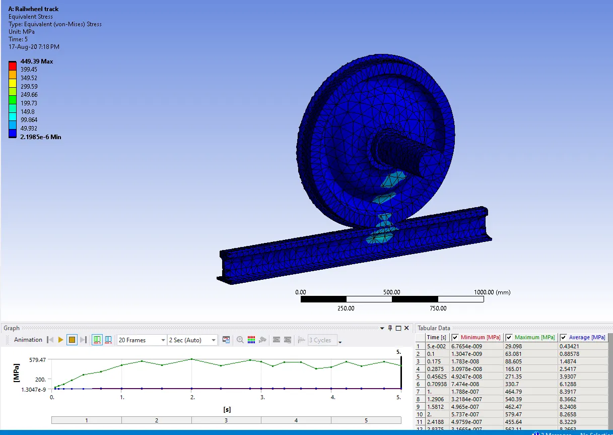
Equivalent stress at 50000 bearing load
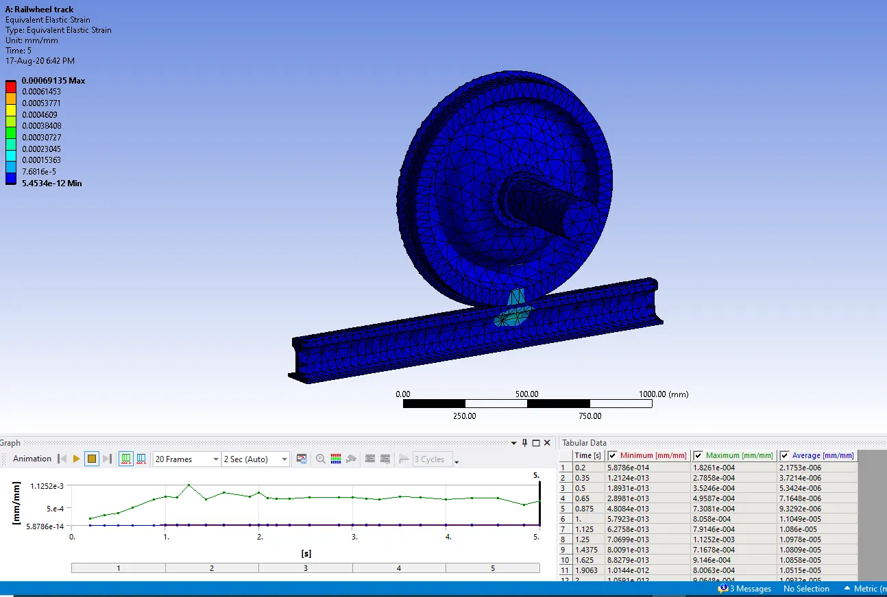
Equivalent strain at 10000 Bearing load
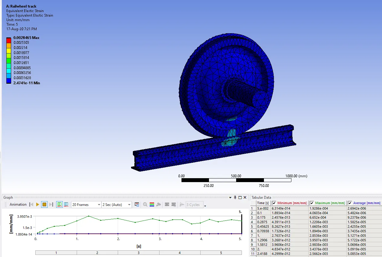
Equivalent strain at 50000 Bearing load
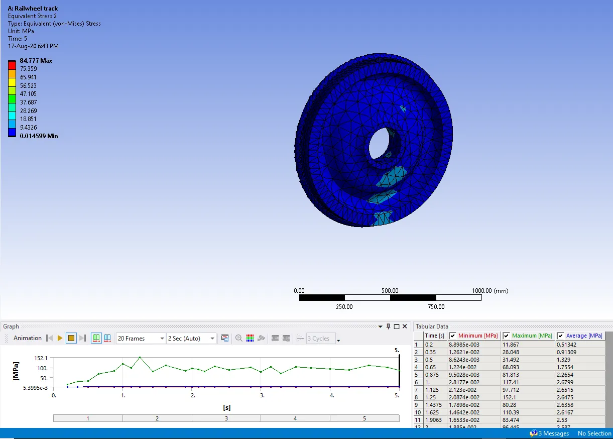
Equivalent stress at wheel only at 10000 Bearing load
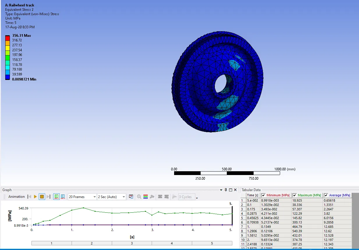
Equivalent stress at wheel only at 50000 Bearing load
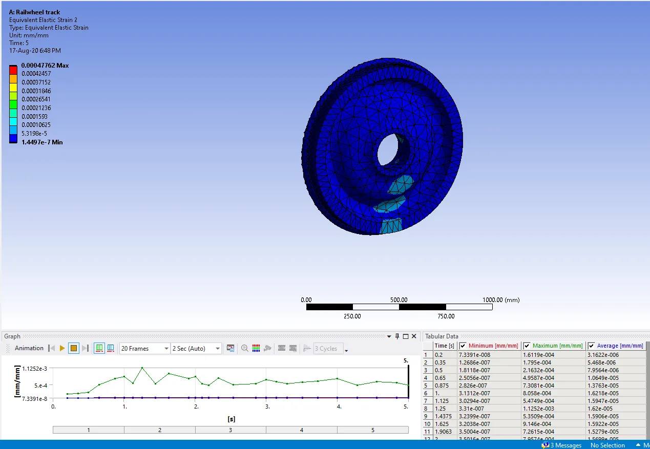
Equivalent strain at wheel only at 10000 Bearing load
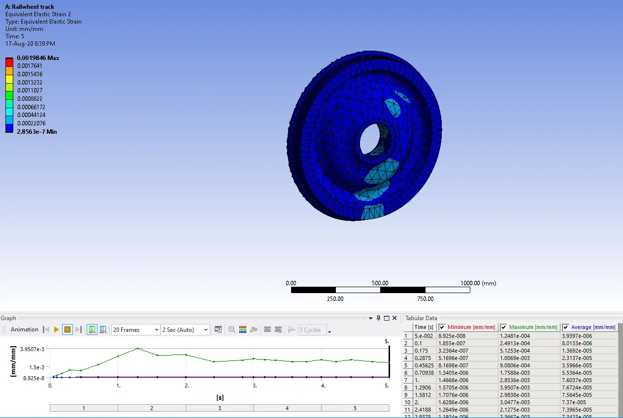
Equivalent strain at wheel only at 50000 Bearing load
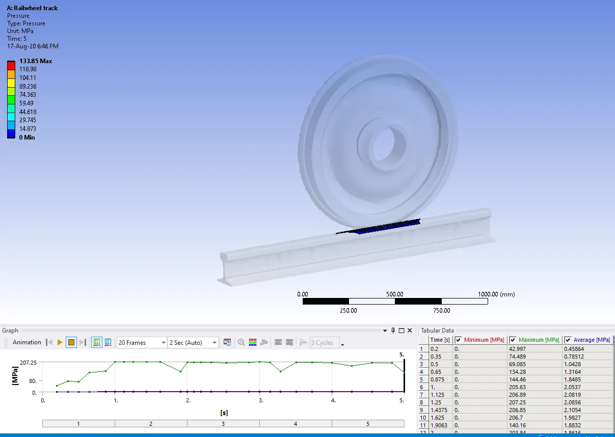
Contact tool pressure at wheel 10000 Bearing load
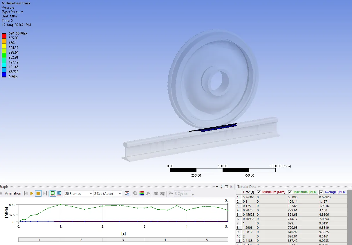
Contact tool pressure at wheel 50000 Bearing load
Contact tool pressure at shaft 10000 Bearing load
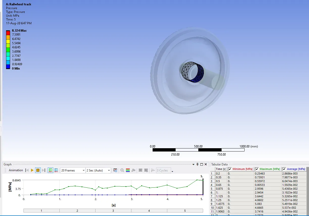
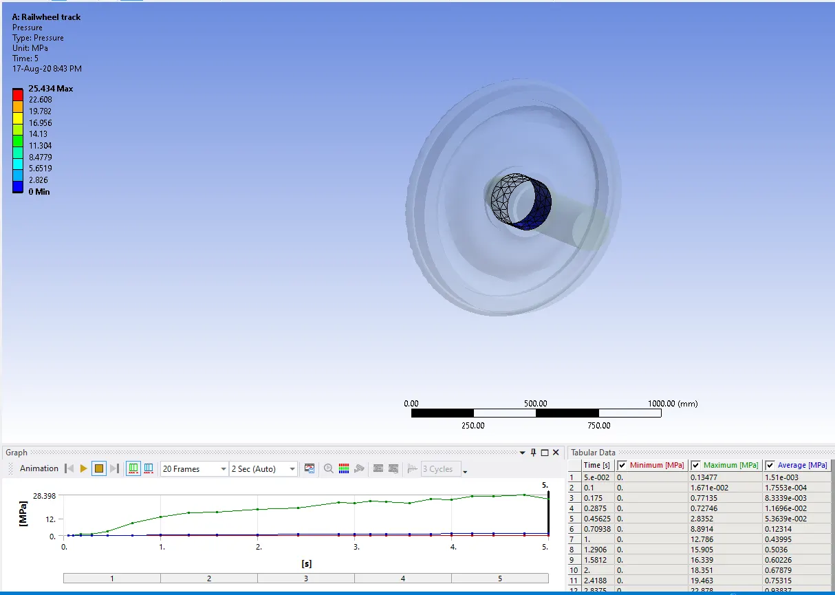
Contact tool pressure at shaft 50000 Bearing load
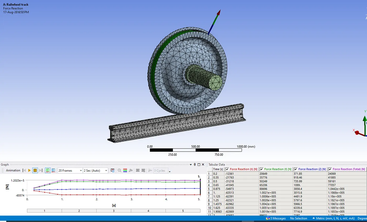
Force reaction at 10000 Bearing load
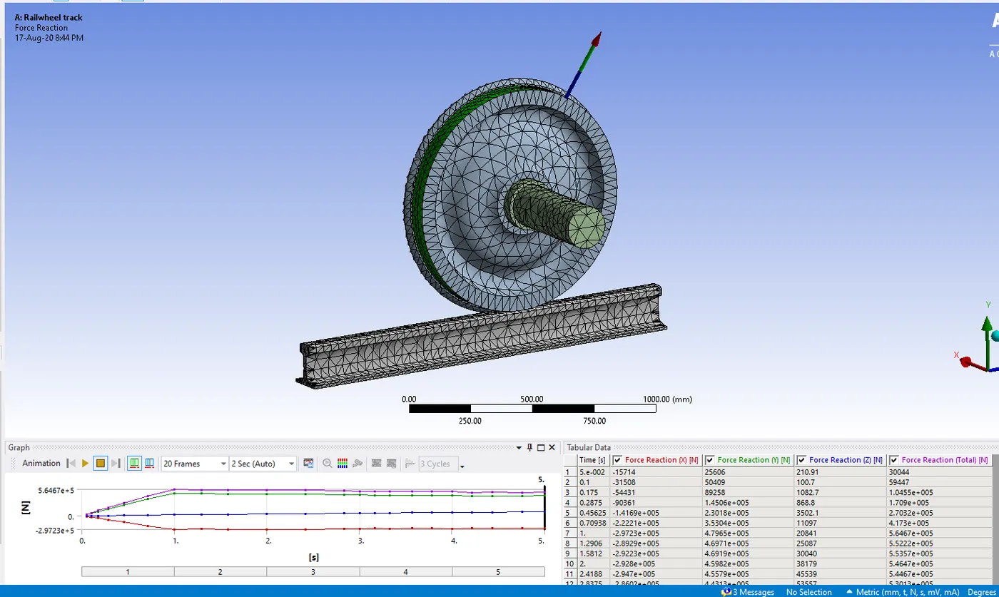
Force reaction at 50000 Bearing load
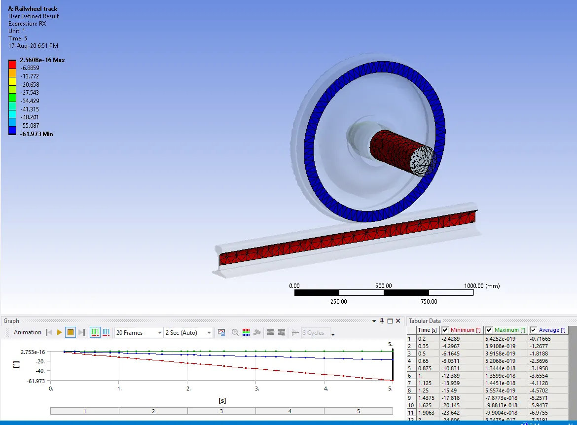
User defined result at 10000 Bearing load
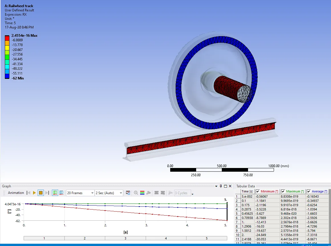
User defined result at 50000 Bearing load
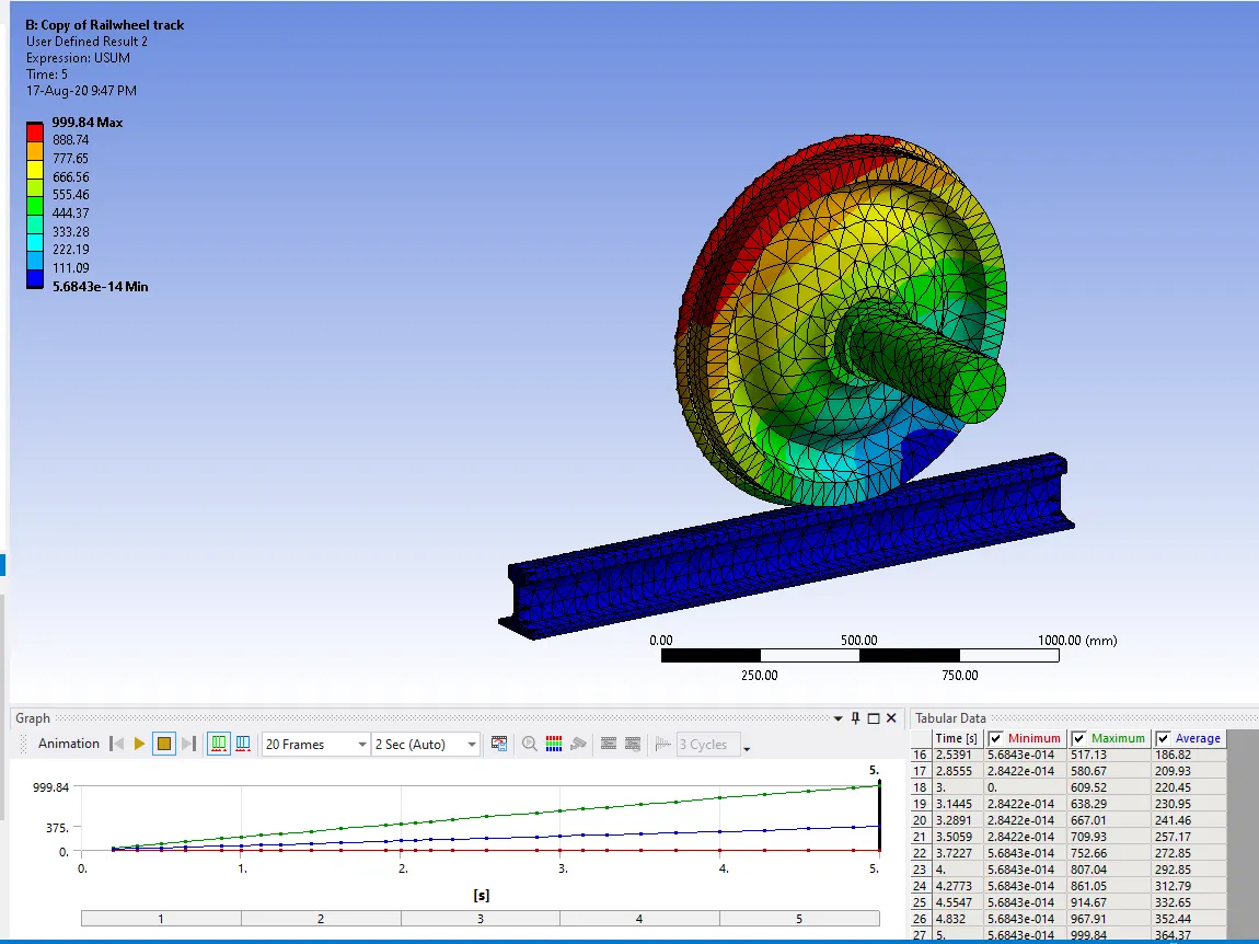
Case 2: Implement a User defined result and calculate the Total Deformation from this result and check if it is the same as that obtained by the inbuilt result by ANSYS for a load of 100000 N.
Conclusion case 1
Total deformation
when the bearing load is 10000 is 999.84 mm
when the bearing load is 5 x 10000 is 1000.1 mm
Equivalent stress
when the bearing load is 10000 is 98.724 Mpa
when the bearing load is 5 x 10000 is 449.39 Mpa
Equivalent strain
when the bearing load is 10000 is 0.00069
when the bearing load is 5 x 10000 is 0.0028
Equivalent stress on wheel
when the bearing load is 10000 is 84.777 Mpa
when the bearing load is 5 x 10000 is 356.31 Mpa
Equivalent strain on wheel
when the bearing load is 10000 is 0.00047
when the bearing load is 5 x 10000 is 0.0019
Pressure on wheel
when the bearing load is 10000 is 133.85 Mpa
when the bearing load is 5 x 10000 is 591.56 Mpa
Pressure on wheel Shaft
when the bearing load is 10000 is 8.324 Mpa
when the bearing load is 5 x 10000 is 25.434 Mpa
force reaction on the wheel
when the bearing load is 10000 is which is coming in the range of -65574 to 1.2023e+5
when the bearing load is 5 x 10000, which is coming is coming around the range of -2.9723e+5 to 5.6467 e+5
Bearing load of 5 times does not have many effect on the total deformation on the wheel track but it has at least 5 times effect on the equivalent stress on wheel track, wheel and the pressure on the wheel and pressure on the wheel shaft does not have many effect. Almost three times value. Force reaction also having a five times variation in the values.
Conclusion case 2
Total deformation has been found when using the expression USUM in the user defined area and that has been become exactly same as the one we got it from original total deformation, which is at the bearing load of 10000 is 999.84 mm