Week 2 Railwheel and Track
RailWheel and Track
OBJECTIVE:-
To perform a static structural analysis on the Railwheel and Track setup where -
Case 1: Multiply the bearing load by 5 times and compare the results with the load of 100000 N. Compare the Total Deformation, Equivalent stress, and the life under both the loads.
Case 2: Implement a User-defined result and calculate the Total Deformation from this result and check if it is the same as that obtained by the inbuilt result by ANSYS for a load of 100000 N.
INTRODUCTION:-
Wheel:
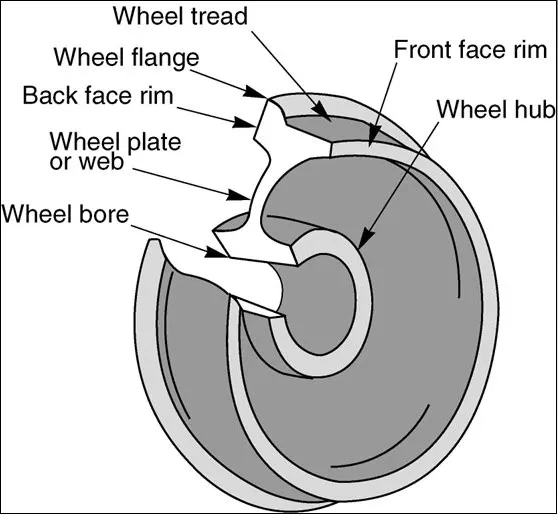
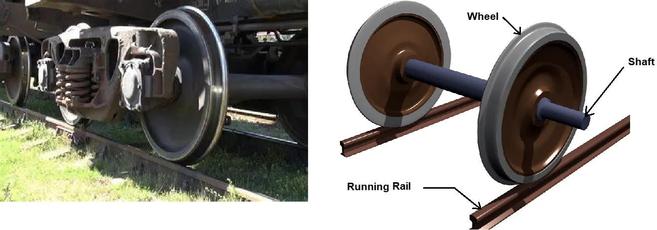
A train wheel or rail wheel is a type of wheel specially designed for use on railway tracks. The wheel acts as a rolling component, typically pushed onto an axle and mounted directly on a railway carriage or locomotive, or indirectly on a bogie (in the UK), also called a truck (in North America). The powered wheels under the locomotive are called Driving Wheels. Wheels are initially cast or forged and then heat-treated to have a specific hardness. New wheels are machined using a lathe to a standardized shape, called a profile, before being installed onto an axle. All wheel profiles are regularly checked to ensure proper interaction between the wheel and the rail. Incorrectly profiled wheels and worn wheels can increase rolling resistance, reduce energy efficiency and may even cause a derailment.
Rail Profile:
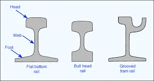
The rail profile is the cross sectional shape of a railway rail, perpendicular to its length. Early rails were made of wood, cast iron or wrought iron. All modern rails are hot rolled steel with a cross section (profile) approximate to an I-beam, but asymmetric about a horizontal axis (however see grooved rail below). The head is profiled to resist wear and to give a good ride, and the foot profiled to suit the fixing system. Unlike some other uses of iron and steel, railway rails are subject to very high stresses and are made of very high quality steel. It took many decades to improve the quality of the materials, including the change from iron to steel. Minor flaws in the steel that may pose no problems in other applications can lead to broken rails and dangerous derailments when used on railway tracks.
PROCEDURE:-
Case-1
A) Bearing Load = 100KN
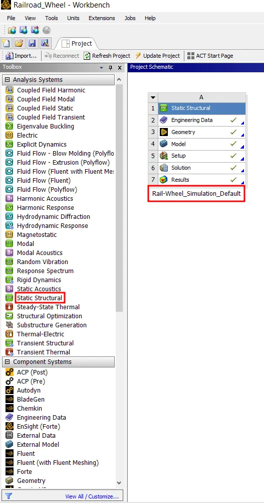
Start the simulation by opening with the Ansys workbench.
Select the static structure from the toolbox as shown below shown.
Engineering Data:-
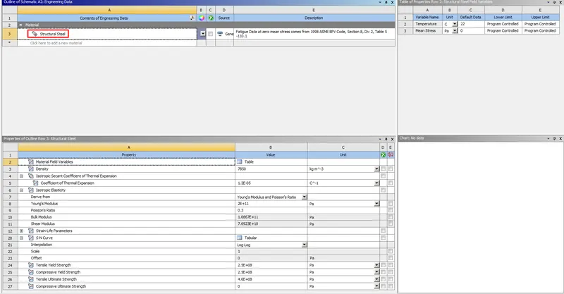
Structured steel is chosen as material for this simulation.
Geometry:-
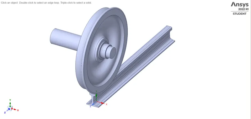
Import the geometry of model that is already provided by right clicking on Geometry and then click on Import. Double click on Geometry to open it in SpaceClaim.
Model:-
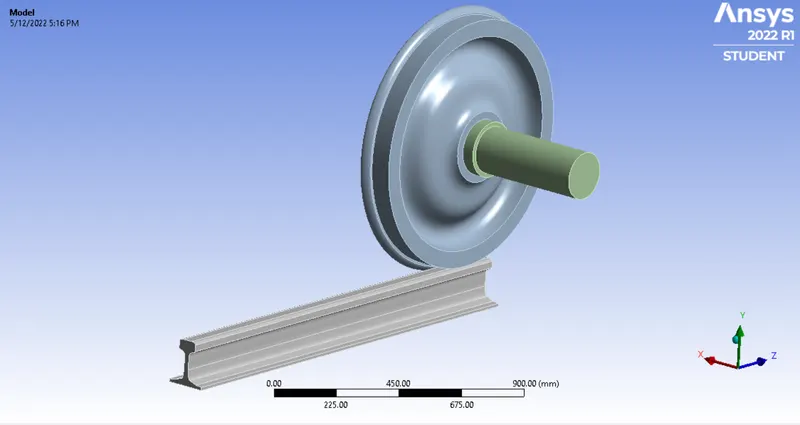
Now right click on Model and then click on Update to update the model. After that double click on the Model to setup the simulation. We have total 3 solid parts here-
1. runningrail
2. wheel
3. shaft
Defining Contacts:-
There are total 2 contacts to be defined-
1. Contact between wheel and runningrail
2. Contact between Wheel and shaft
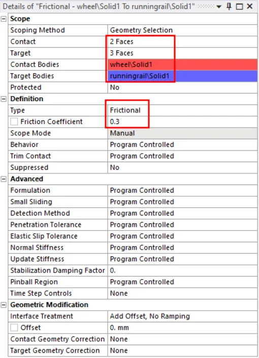
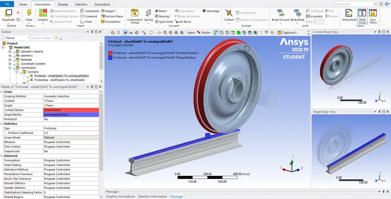
1. Contact between wheel and runningrail:
Frictional contact is defined here having Friction Coefficient = 0.3 as shown, where wheel is contact and runningrail is target.
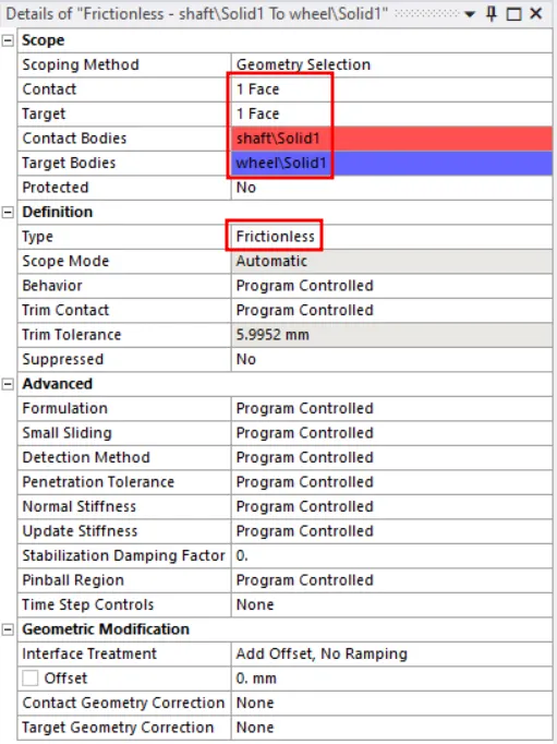
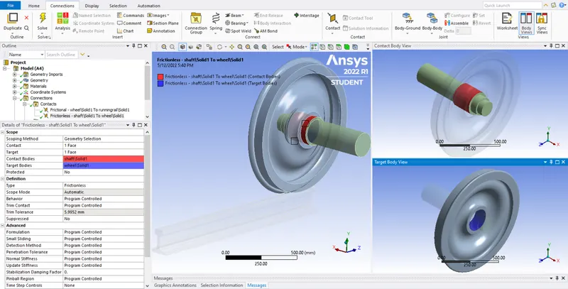
2. Contact between wheel and Shaft:
Frictionlass contact is defined here having shaft as contact and whell as target bodies as shown.
Defining Joints:-
Total 3 joints are defines here mentioned below.
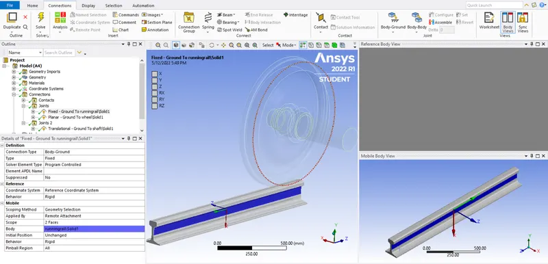
1. Fixed joint - Fixed joint is defined for the runningrail which has to be fixed w.r.t ground as shown below.
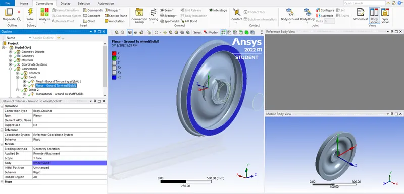
2. Planer joint - Planer joint is defined for wheel because the wheel face has to be in the same plane throughout.
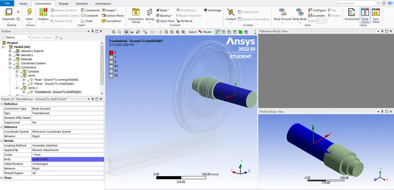
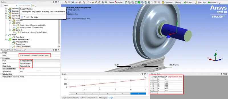
3. Translational joint - Translational joint is defined for shaft because the shaft has to move in linear motion parallel to the runningrail.
Meshing:-
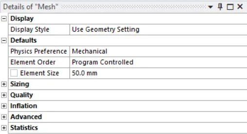
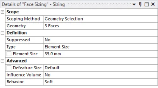
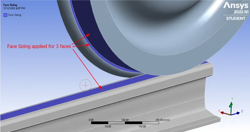
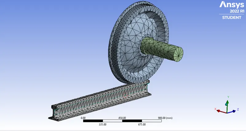
Element size of 50mm is used to mesh the model but for some areas, the mesh size is kept 35mm using Face Sizing.
Analysis Settings:-
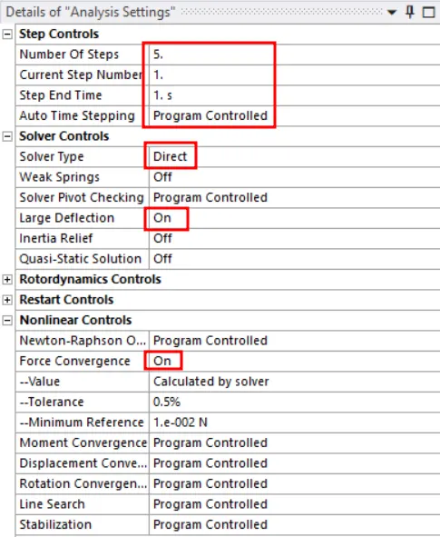
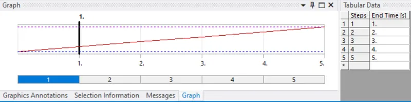
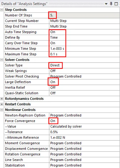
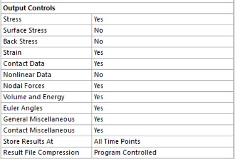
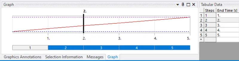
Simulation is defined to be finished in 5 steps where the analysis settings specified for step 1 is different than other 4 steps from 2-5.
analysis settings for step 1 -
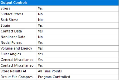
analysis settings for other steps -
Defining Joint Forces:-
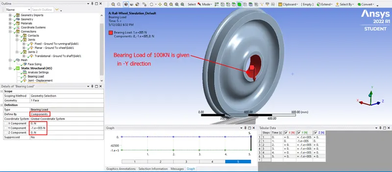
500 mm displacement is given to the shaft in local X direction having 100mm in each step as shown. If the direction is not proper then we can change the direction of axis by going to joints and change the Principal Axis from X to Z in Reference Coordinate System for shaft.
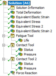
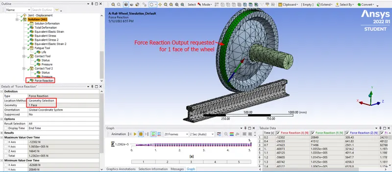
Requesting for Output Results:-
Equivalent Stress 2 and Equivalent Elastic Strain 2 are requested for wheel whereas Contact Tool and Contact Tool 2 are requested for both the contacts individually.
B) Bearing Load = 500KN
NOTE:- Same procedure can be used to setup simulation for 500KN Bearing Load.
RESULTS:-
100KN Bearing Force -
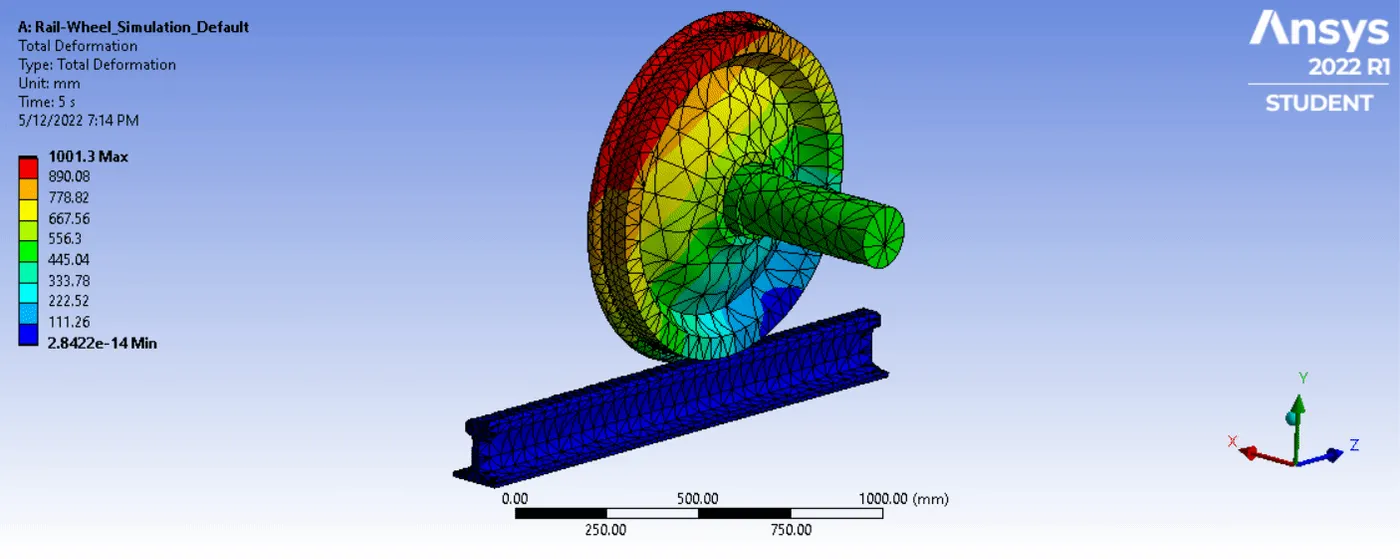
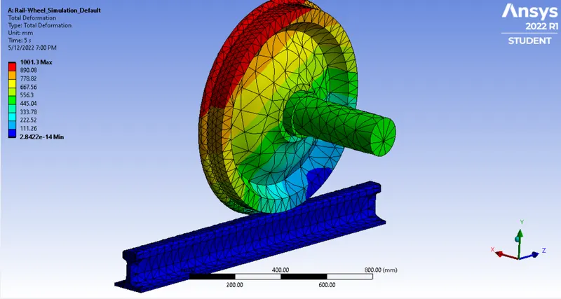
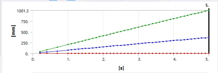
Total Deformation:-
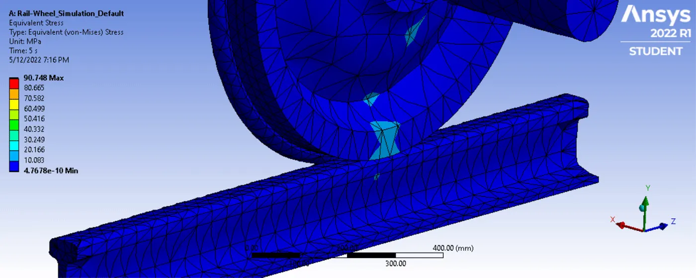
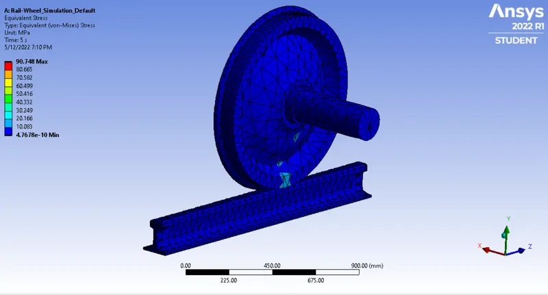
Equivalent Stress:-
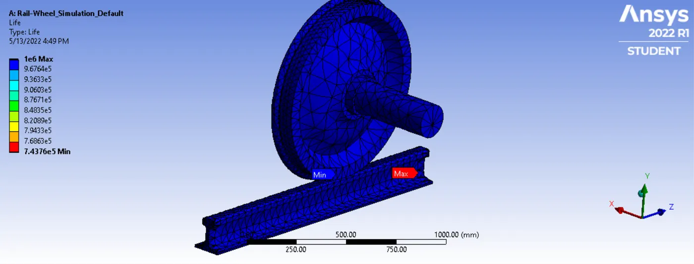
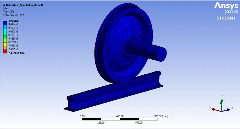
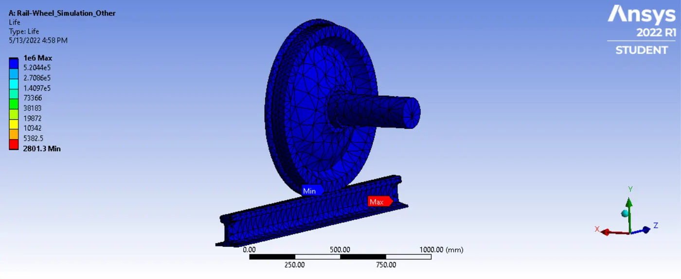
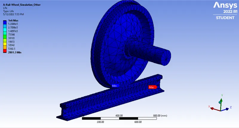
Life:-
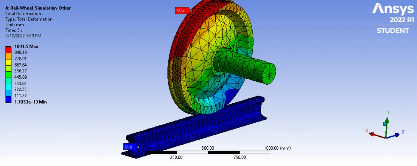
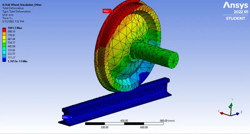
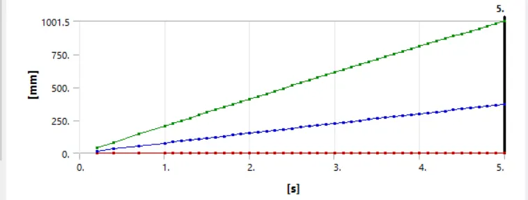
Total Deformation:-
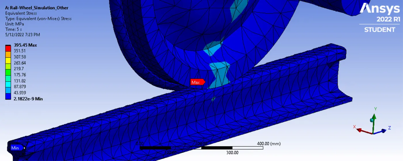
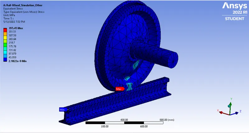
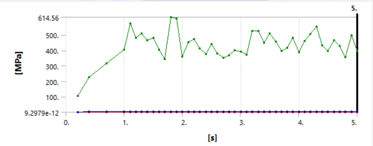
Equivalent Stress:-
Life:-
COMPARISION:-
| Bearing Load = 100KN | |
| Parameter | Max. |
| Total Deformation | 1001.3mm |
| Eq. Stress | 90.748Mpa |
| Life | 10^6 |
| Bearing Load = 500KN | |
| Parameter | Max. |
| Total Deformation | 1001.5mm |
| Eq. Stress | 395.45Mpa |
| Life | 10^6 |
Case-2
User Defined Result:-
Depending on the requirements, we can create User Defined Results to output the needed result. There are various output quantities given in the Worksheet of Ansys Mechanical. Somehow, if any result is not given as output automatically, than we can write expression for that result and get required results.
If we want Total Deformation results, then we can use algebraic equation for Resultant Deformation in the form of vector quantities. We know that if there are three vectors present and we want to find the reultant than the formula to find resultant will be -
R^2 = Fx^2 + Fy^2 +Fz^2 + 2 FxFy cos a +2 FyFz cos b + 2FzFx cos c
a.,b,c are angles. Since the vectors are perpendicular to each other, the angle is 90 degree and thus cos90 = 0 so the final formula becomes -
R^2 = Fx^2 + Fy^2 +Fz^2
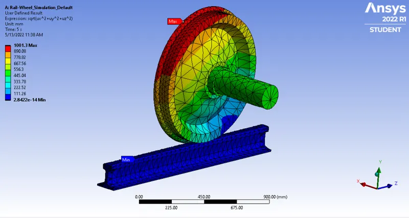
Here we want to find out the Total Deformation as a User Defined Result and want to check if it is similar to inbuilt result.
So, symbol for the Deformation used is U.
 Where, ux, uy and uz are deformations in x,y and z directions respectively.
So, for expression we can write it in the form as given below:

Inbuilt Result by ANSYS-
| Bearing Load = 100KN | |
| Parameter | Max. |
| Total Deformation | 1001.3mm |
User Defined Result-
| Bearing Load = 100KN | |
| Parameter | Max. |
| Total Deformation | 1001.3mm |
CONCLUSIONS:-
Case-1 -
It was found that the total deformation in both cases is approximately the same but to be more specific, the value of Total Deformation in the case of 500KN Bearing load is slightly greater(1001.5mm) than the 100KN(1001.3mm). However, the stresses and strains generated in the Rail Wheel Track model having a bearing load of 500 KN are greater in comparison Rail Wheel Track model having a bearing load of 100 KN. The fatigue tool results indicated that the life cycles of the Rail Wheel track model are similar irrespective of the Bearing Load values which is 10^6.
Case-2 -
we can say that with the help of user defined result, the total deformation has the same value as that calculated by direct solution in case of 100KN.