Week 2 Railwheel and Track
Aim : To perform a static structural analysis on the Railwheel and Track setup.
Objectives :
Case 1 : Multiply the bearing load by 5 times and compare the results with the load of 100000 N. Compare the Total Deformation, Equivalent stress and the life under both the loads.
Case 2 : Implement a User defined result and calculate the Total Deformation from this result and check if it is the same as that obtained by the inbuilt result by ANSYS for a load of 100000 N.
Procedure :
Static structural and Engineering data :
- Create static structural model.
- Go to engineering data set the material as per requirement.
Geometry :
- Open spaceclaim.
- Import the geometry.
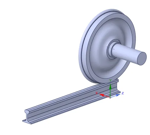
Model Setup :
1. Contacts :
- Open contacts.
- Right click and rename based on defination both contacts.
- Right click and Flip the contacts.
- For rail and wheel give frictional contact with coeff. of friction as 0.3.
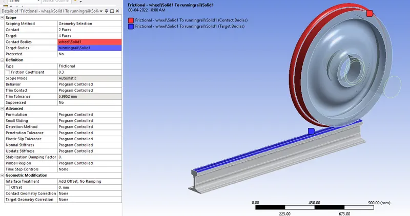
- For Shaft and wheel use frictionless contact.
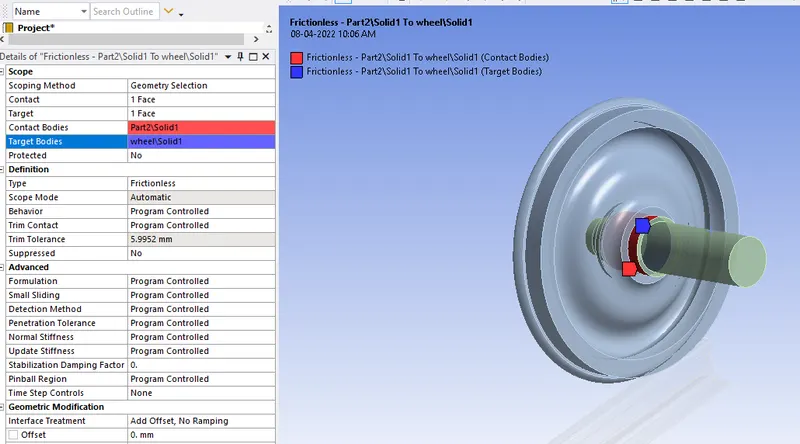
2. Joints :
- Right click on connections and create joints.
- Create fixed joint for rail.
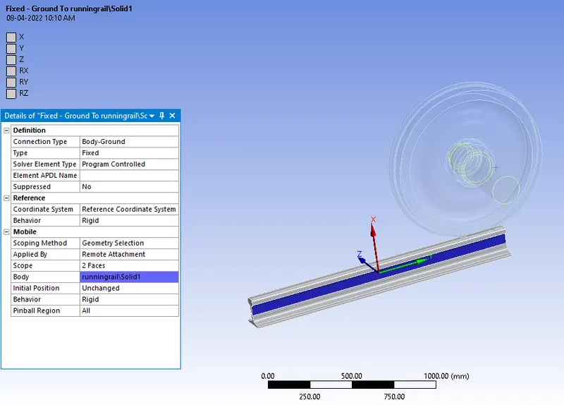
- Create translational joint for shaft to provide translational motion.
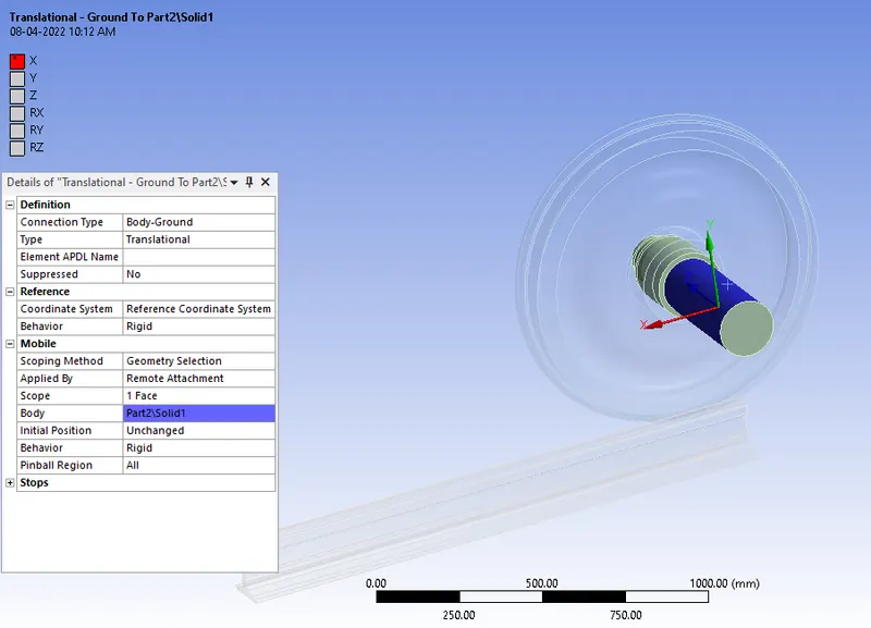
- Create planar joint for wheel.
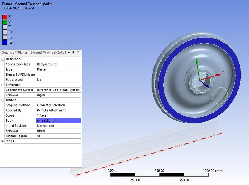
3. Meshing :
- Open mesh.
- Give element size of 50 mm.
- Create face sizing of size 35 mm for the three faces in contact.
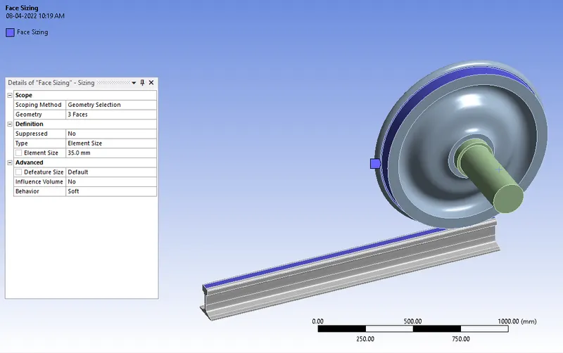
- Click on generate mesh.
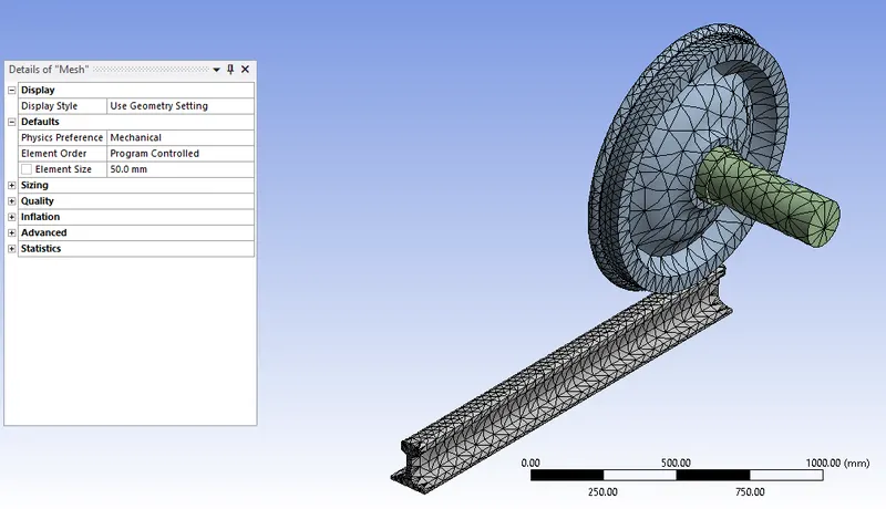
4. Analysis setting :
- No. of steps = 5
- Auto time stepping = Program controlled.
- Solver type = Direct.
- Large deflection =On.
- In Output Controls all parameters should be yes.
- In Non-linear controls Force convergence should be on.
- Now, use shift key and select 2 to 5 time step and change parameters.
- Auto time stepping = on
- Define by = time.
- Carry over timestep = On
- Minimum timestep = 1E-3 s
- Maximum timestep = 0.1 s
- In Output Controls all parameters should be yes.
- In Non-linear controls Force convergence should be on.
5. Joint load :
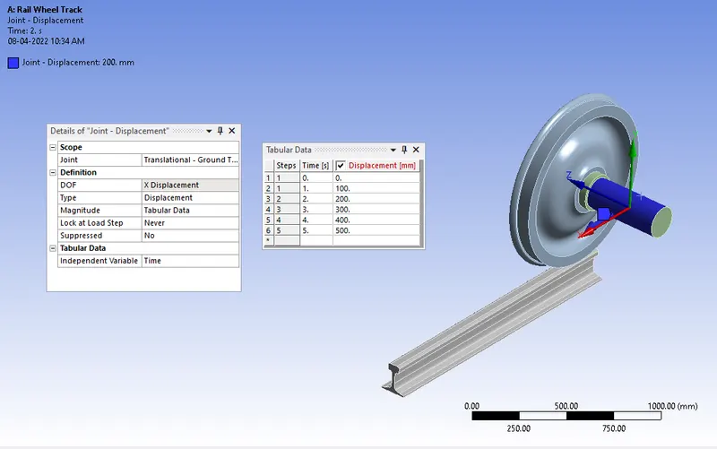
- Create translational displacement of 0 to 500 mm for translational joint.
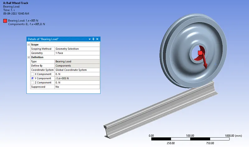
- Create bearing load of 100000 N on wheel.
- Set Y-component as a input parameter for running simulation for 500000 N load.
6. Solution :
The following parameters need to be evaluated for the results of the rail wheel and track :
- Equivalent Von-mises stress.
- Total deformation.
- Life cycle.
- User-defined result.
Results :
Case 1 :
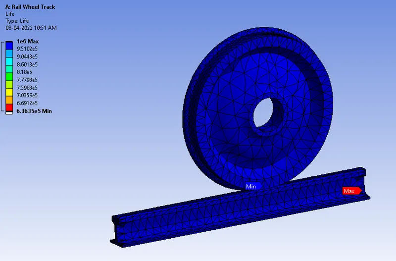
Part A : For Bearing load of 100000 N.
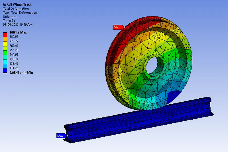
Total Deformation :
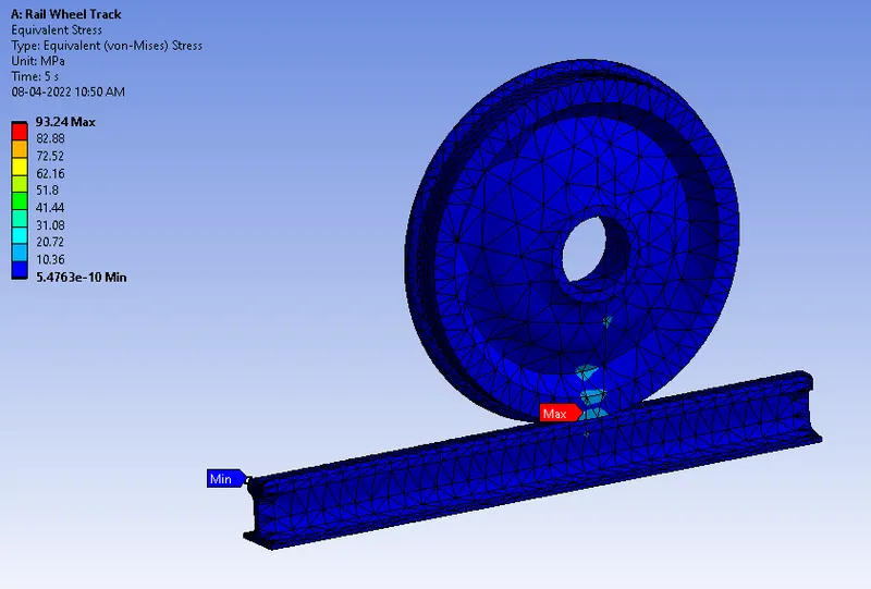
Equivalent Stress :
Life Cycle :
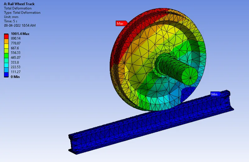
Part B : For Bearing load of 500000 N.
Total Deformation :
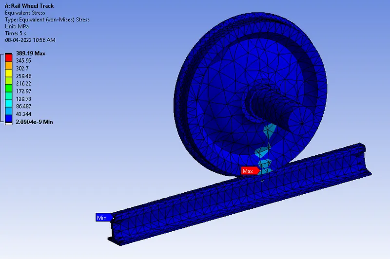
Equivalent Stress :
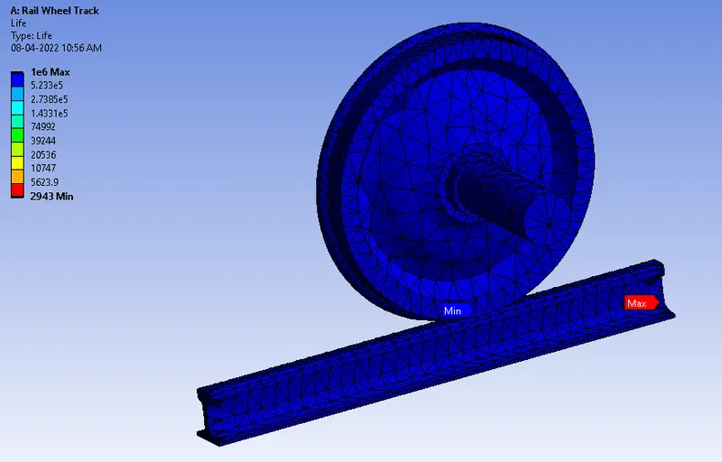
Life Cycle :
Comparison of results :
| Sr.No. | Results | 100000 N | 500000 N |
| 1 | Total deformation Minimum (mm) | 0 | 0 |
| 2 | Total deformation Maximum (mm) | 1001.2109 | 1001.4025 |
| 3 | Equivalent stress Minimum (MPa) | 5.4762 E-10 | 2.0903 E-09 |
| 4 | Equivalent stress Maximum (MPa) | 93.2399 | 389.1917 |
| 5 | Life cycle Minimum | 6.3635 E5 | 2943 |
| 6 | Life cycle Maximum | 1 E6 | 1 E6 |
The result shows that as the load increases, force reaction increases. The equivalent stress and deformation increases, the force is directly proportional to the stress value.
Case 2 : Implement a User defined result and calculate the Total Deformation from this result.
User-defined Result :
- Right click on the solution insert the User defined Result.
- The expression used to evaluate the result expression used is UX + UY +UZ and the output unit is displacement.
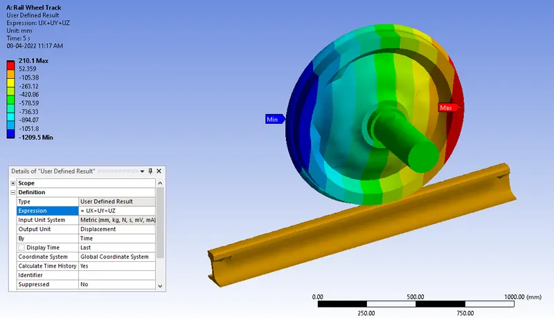
- Total deformation for the user defined is same as as that obtained by the inbuilt result by ANSYS for a load of 100000 N.