Week 2 Railwheel and Track
Aim
a) To perform structural analysis on the given railwheel track setup in terms of total deformation, equivalent stress and the life.
b) To implement a user defined result and to determine total deformation value from that.
Procedure:
1. Engineering Data
First of all, we have opened ANSYS Workbench and selected the static structural analysis tool. For engineering data, we have considered structural steel only.
2. Imparting the Geometry
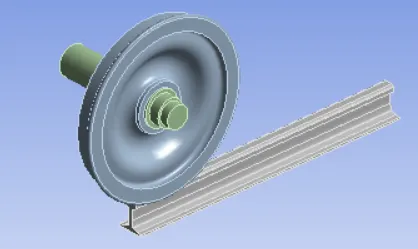
Geometry was loaded in the ANSYS workbench by import geometry option. Given railwheel track 'model was then loaded in ANSYS.
3. Material Assignment
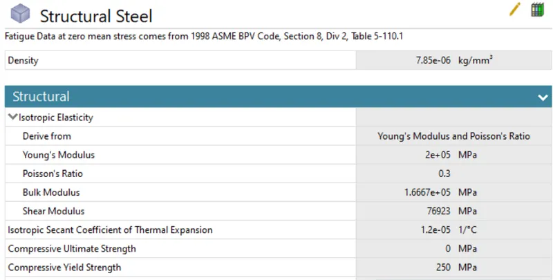
From the model option in static structural module, edit option has been selected to do the simulation work. After this the material was assigned as structural steel to the given model. The properties of structural steel given below:
4. Connections
4.1 contact Details
4.1.1 Frictional Contact
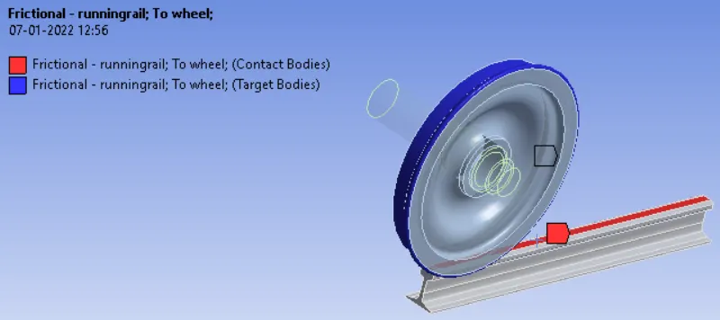
Frictional contact was created between the wheel surface and rail track. The coefficient of friction value was 0.3.
4.1.2 Frictionless Contact
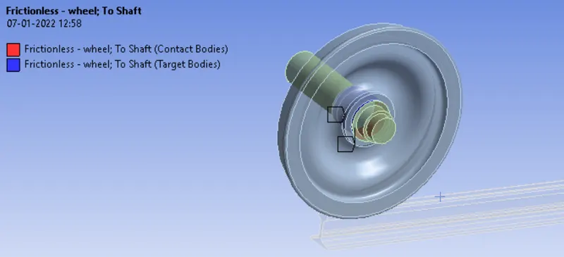
As shown in the above figure, shaft and wheel internal surface was connected by frictionless contact.
4.2 Joint Details
4.2.1 Fixed Joint
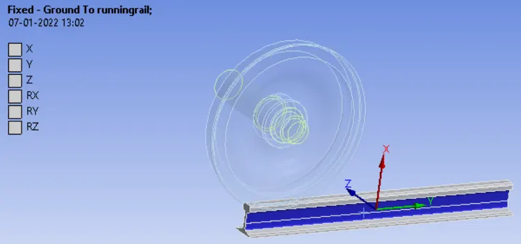
As shown above, fixed joint was assigned to the side surfaces of rail track.
4.2.2 Translatory Joint
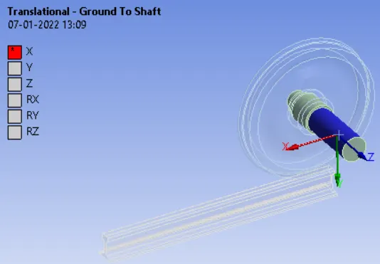
As shown above, translatory joint was assigned to the shaft to move in X Direction.
4.2.3 Planar Joint
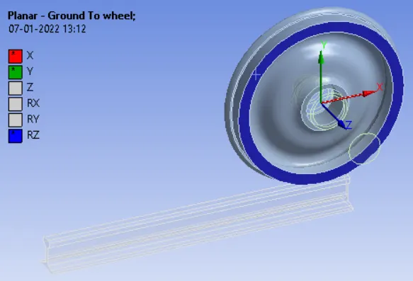
As given in the figure, planar joint was created by selecting the given blue coloured surface to constraint it to move in the X-Y Plane.
5. Mesh Details
5.1 Coarse Mesh
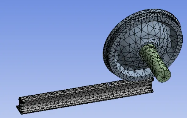
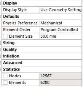
As shown in above figure, coarse mesh of element size 50.0 was created for the larger dimensions areas.
5.2 Finer Mesh
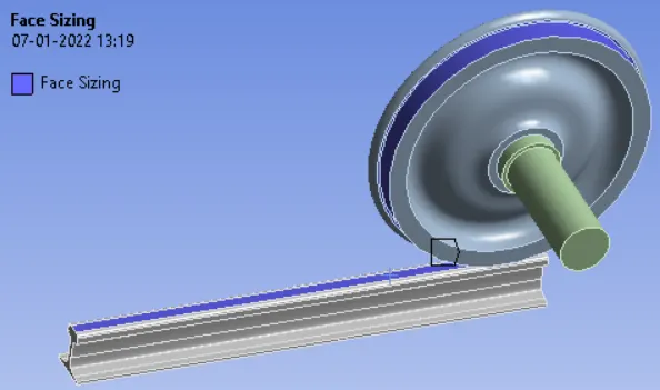
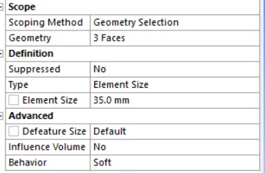
As shown above, smaller dimension areas were given as finer mesh of size 35.0 mm.
6. Analysis Settings
Analysis was done in five steps of wheel motion. The seperate settings of steps are given below:
6.1 First Time Step
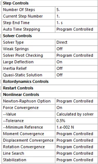
Above figure shows the first time step settings with auto time stepping as program controlled.
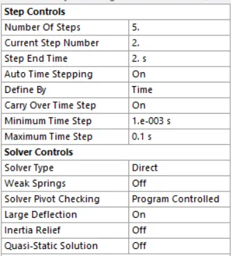
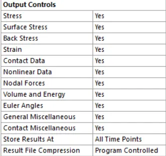
6.2 Last four time steps
7. Load Details
7.1 Displacement
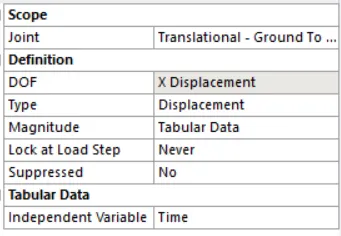

Displacement was given to the shaft body in five steps as shown in the above table. Maximum Displacement Travelled by shaft was 500 mm.
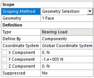
7.2 Bearing Load
Results
Case 1 - 100000N
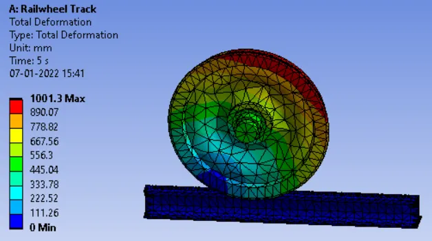
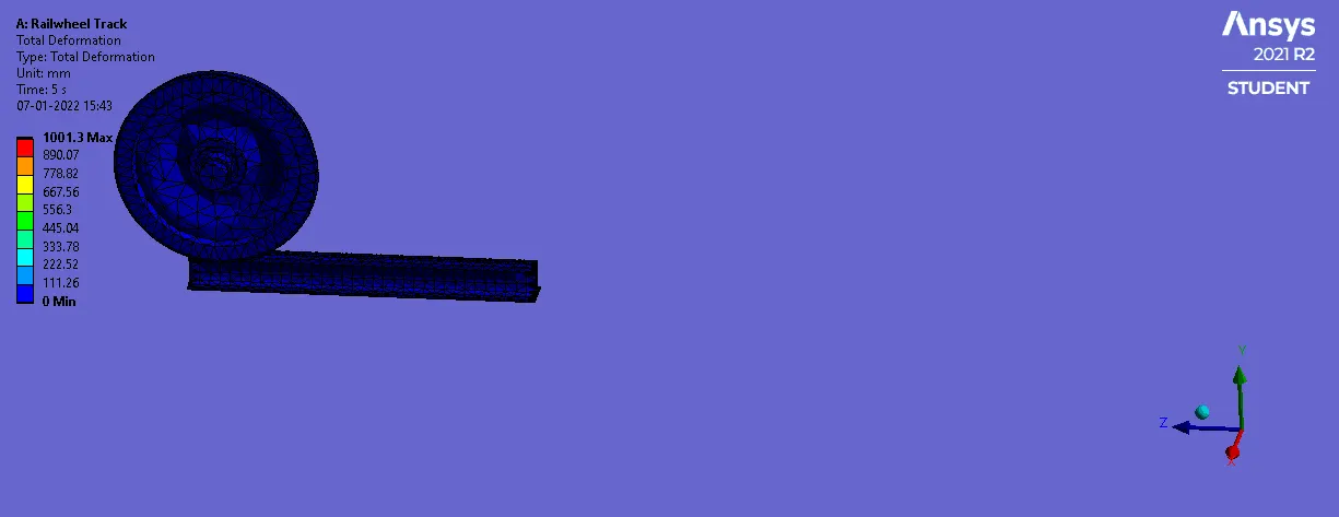
1.1 Total Deformation
1.2 Equivalent Stress
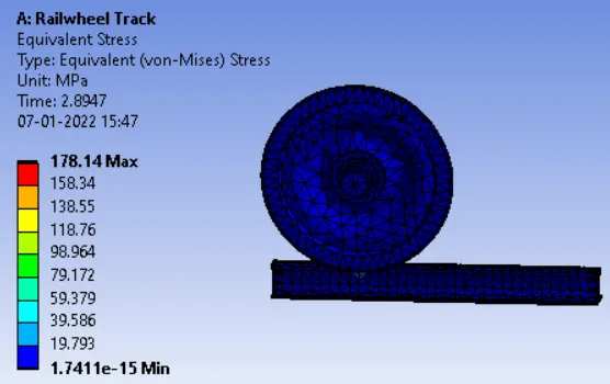
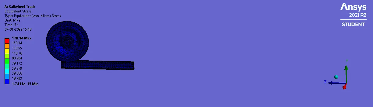
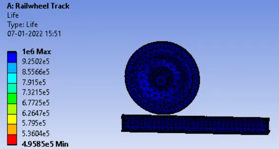
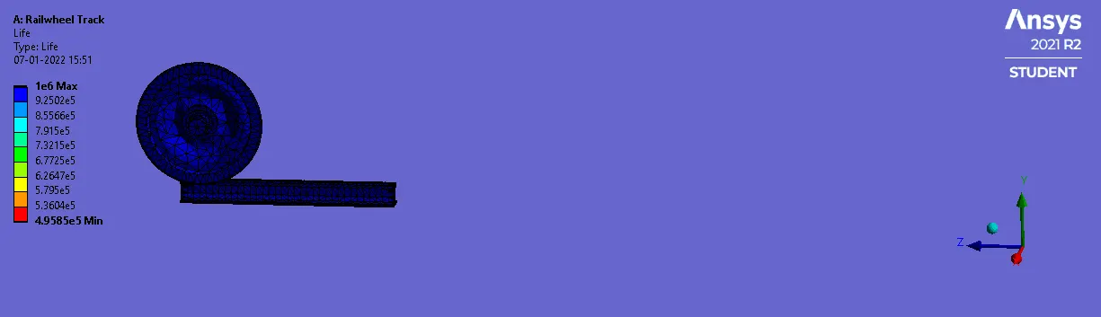
1.3 Life
Case 2 - 500000 N
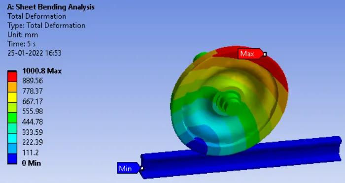
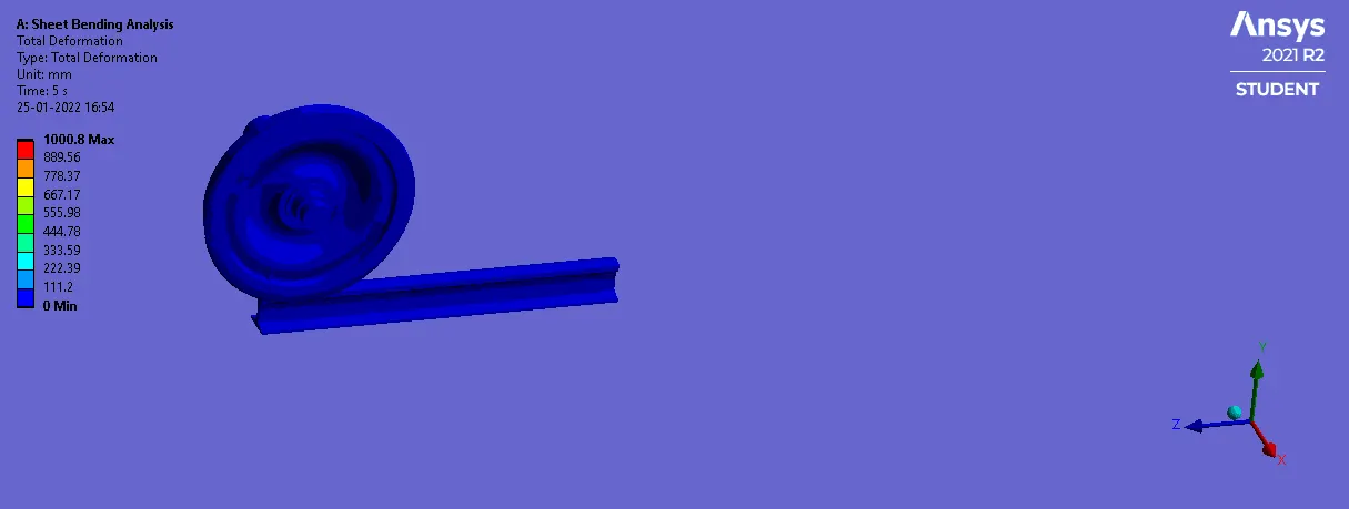
2.1 Total Deformation
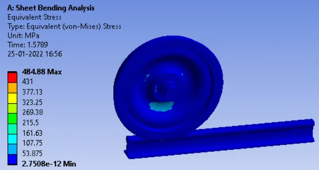
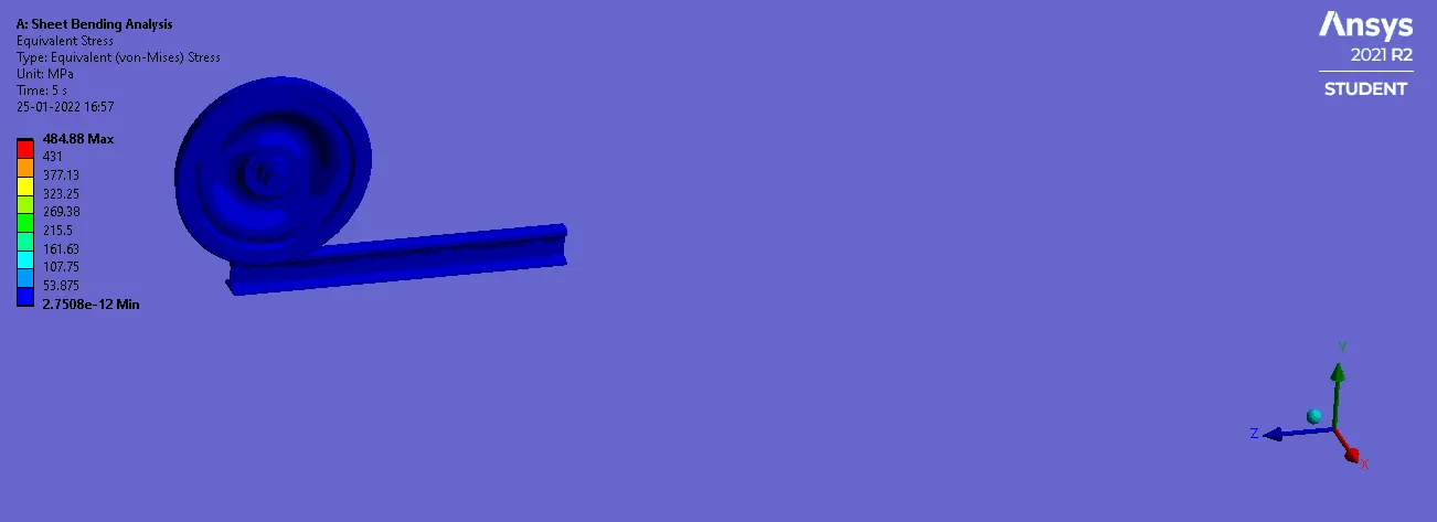
2.2 Equivalent Stress
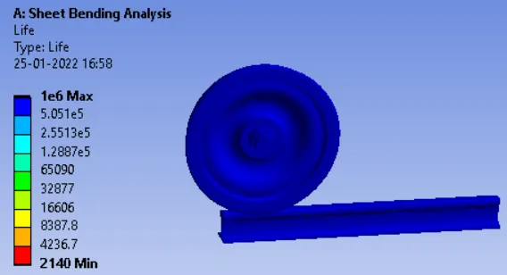
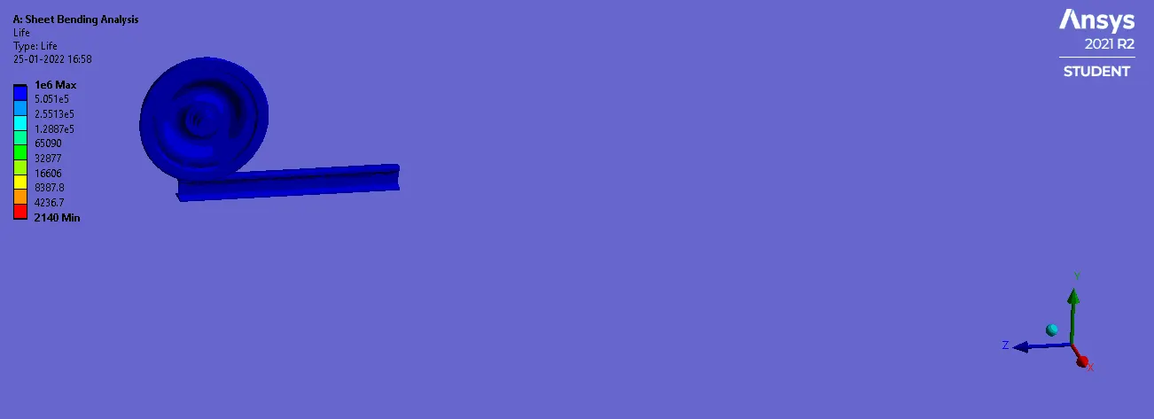
2.3 Life
Case 3 - User Defined Result
We have assumed a user defined result which had the following details:
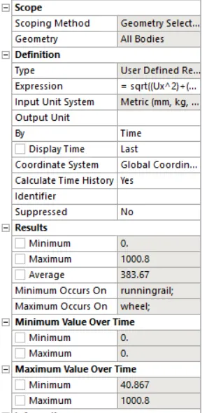
When the total deformation was calculated with the help of this user defined result, the following details were extracted-
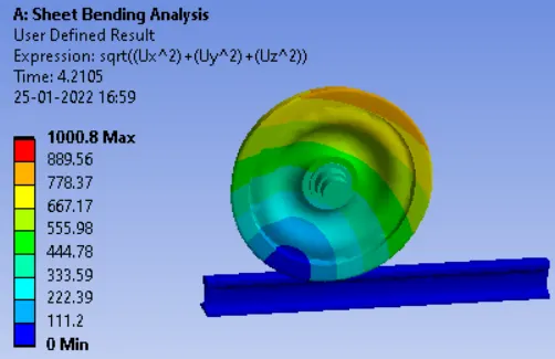
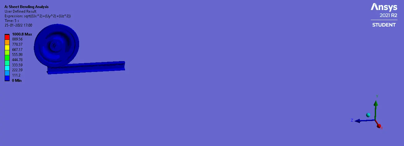
In this case the load was 500000 N.
Conclusions
a) From the results, we can conclude that total deformation is more in case of 100000 N but on the other hand life and equivalent stress both are larger for 500000 N.
b) Similarly we can say that with the help of user defined result, the total deformation has the same value as that calculated by direct solution in case of 500000 N.