Week 2 Railwheel and Track
AIM : To perform a Static Stress Analysis on a Railwheel & Track setup under different load conditions and also create a user defined result to calculate the Total Deformation and compare it with the inbuilt result from ANSYS-Workbench.
Objectives :
Case 1: Multiply the bearing load by 5 times and compare the results with the load of 100000 N (As done in week 2 video). Compare the Total Deformation, Equivalent stress and the life under both the loads
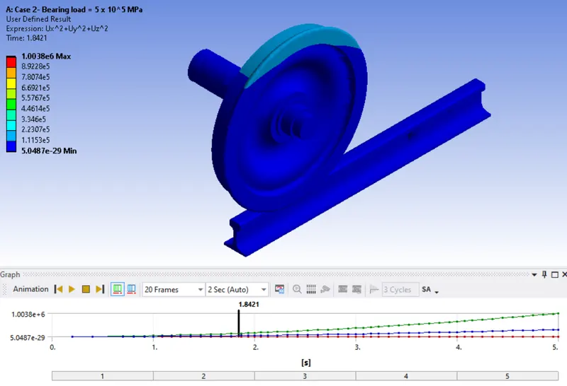
Case 2: Implement a User defined result and calculate the Total Deformation from this result and check if it is the same as that obtained by the inbuilt result by ANSYS for a load of 100000 N.
PROCEDURE:
After Opening the Workbench select Static Structural then upload the model in IGES or STEP format in the geometry model.
Select the Material we need from the Engineering Data but for this Simulation, we are using default material here. Which will be assigned automatically.
After opening this model in Mechanical Module. Here we have to provide the connections and joints for the assembly.
In connections we will provide Frictional contact between Wheel and track and Frictionless contact between Wheel inner hub and shaft using following settings shown in the image below.
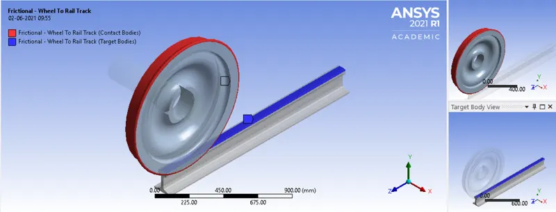
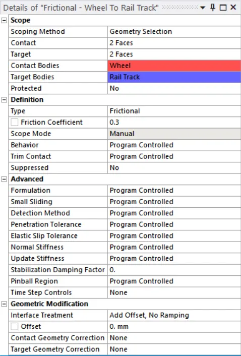
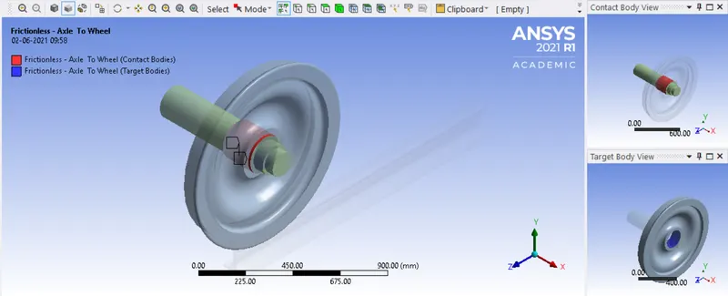
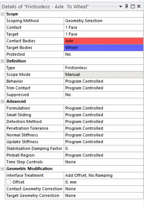
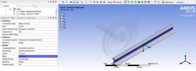
In Joints we will provide the rail is fixed Joint along all the 6 degree of freedom.
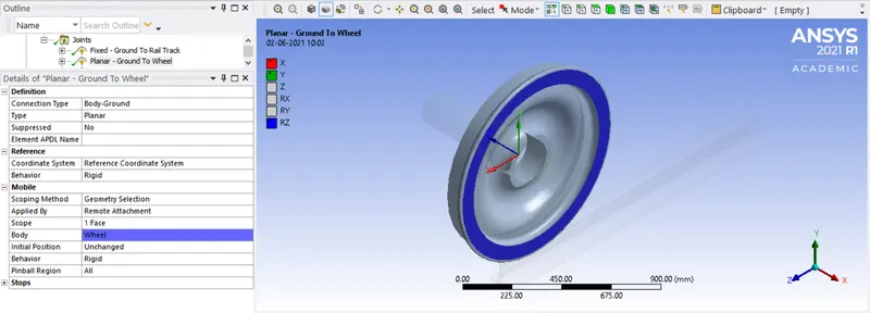
We will provide Planar joint along the surface of the wheel.
Translation joint is provided with shaft in X-axis.
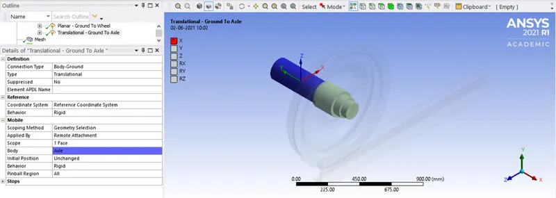
So the wheel is constrained along Z-Plane, RX and RY. Hence it will be able to move only in X & Y direction and Rotate along RZ direction.
To calculate the stress between the Wheel & Rail we will be including a Mesh sizing for the areas of contact between the wheel and rail track. This way the accuracy can be increased in important areas. We will keep the element size to 35mm for the important areas and else to 50mm.
Now providing the loads we will provide the bearing load on the inner hub of the wheel by hiding the shaft. A bearing load of 100000 N is applied along the downward Y direction.
Here 5-times step loading is provided. A uniform load will be given in all 5-times step.
Next the displacement is provided by selecting the shaft with 5-times step loading with the tabular representation. Here we will give displacement of 500 mm in X direction such that in each step 100mm is moved. So gradually 100, 200, 300, 400 & 500 is the values for each time step.
Then the Analysis setting will be provided. The first step will be Program controlled and from secong time step we will provide the minimum and maximum time step.
Results:
Case 1-Bearing load = 100000 N
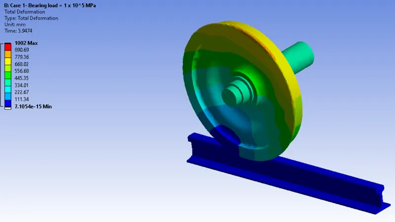
Total Deformation :
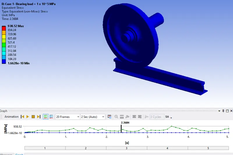
Equivalent Stress :
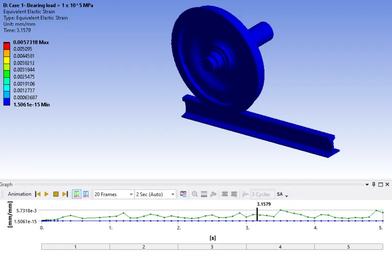
Equivalent Strain :
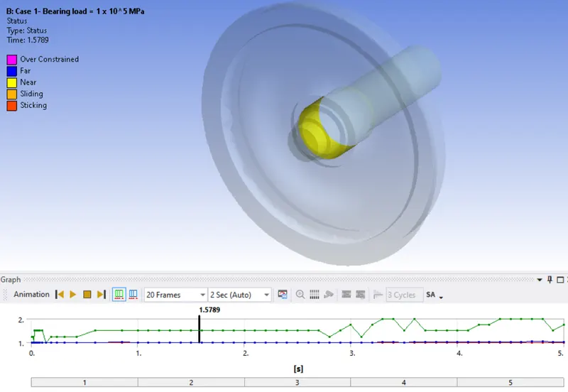
Contact status between axle & wheel:
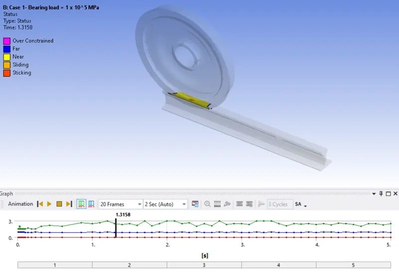
Contact Status between wheel & track :
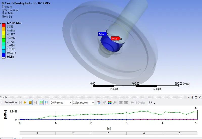
Pressure Applied between axle & wheel:
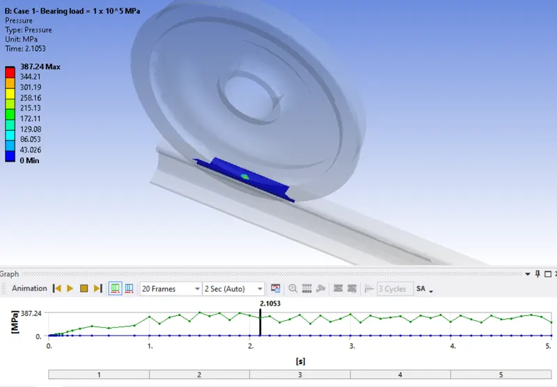
Pressure applied between wheel & track :
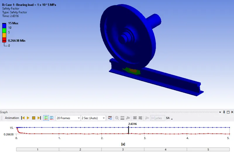
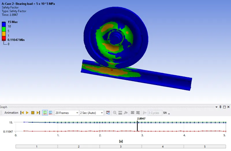
Factor of Safety :
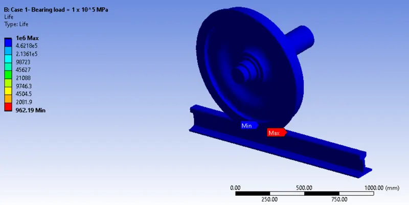
Life Cycle :
User Defined Result :
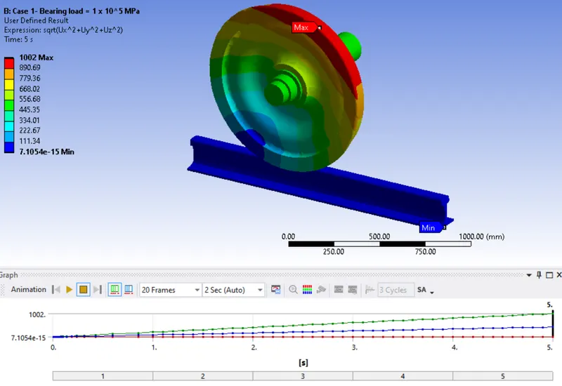
Case 2-Bearing load = 500000 N
Total Deformation :
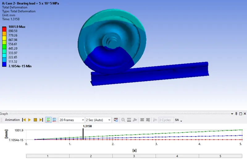
Equivalent Stress :
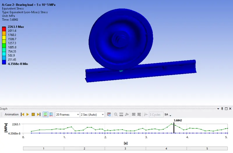
Equivalent Strain :
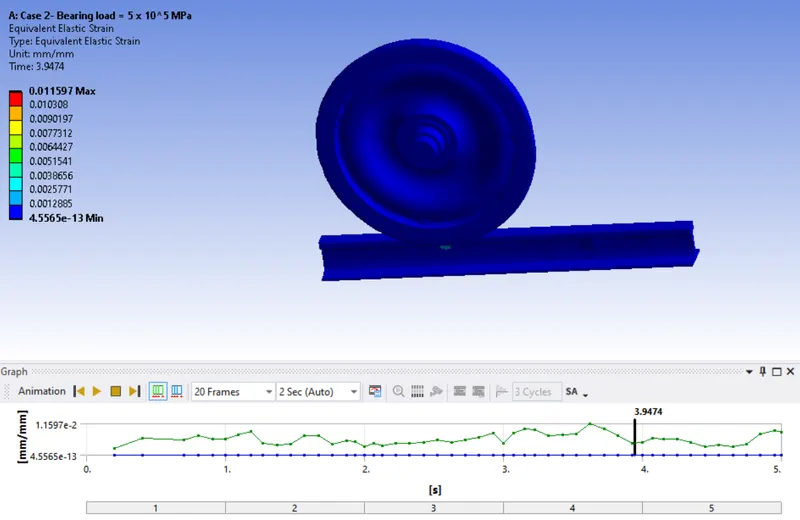
Contact status between axle & wheel:
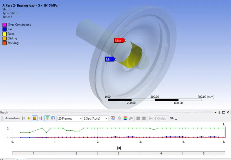
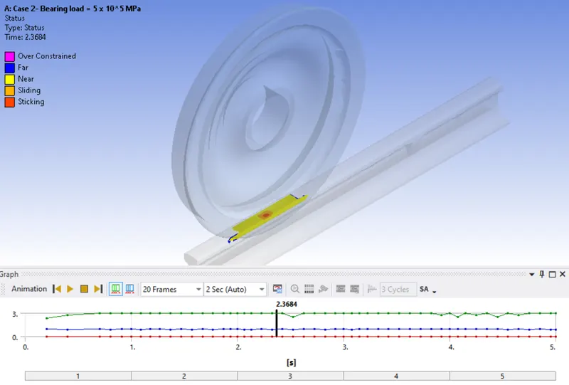
Contact Status between wheel & track :
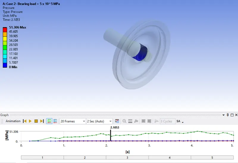
Pressure Applied between axle & wheel:
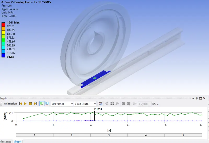
Pressure applied between wheel & track :
Factor of Safety :
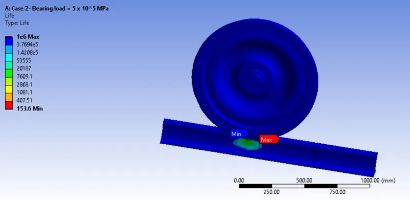
Life Cycle :
User Defined Result :
| Parameters | Case 1 | Case 2 |
| Total Deformation |
Max = 1002 mm Min = 7.1 e-15 mm |
Max = 1001 mm Min = 7.1 e-15 mm |
| Equivalent Stress |
Max = 938.5 MPa Min = 1.6 e-10 MPa |
Max = 938.5 MPa Min = 1.6 e-10 MPa |
| Equivalent Strain |
Max = 0.005 Min = 1.5 e-15 |
Max = 0.01 Min = 4.5 e-13 |
| Pressure - Axle & Wheel |
Max = 6.2 MPa Min = 0 MPa |
Max = 51.3 MPa Min = 0 MPa |
| Pressure - Wheel & Track |
Max = 387.24 MPa Min = 0 MPa |
Max = 1041 MPa Min = 0 MPa |
| Life Cycle |
Max = 1 e6 Min = 962 |
Max = 1 e6 Min = 153.6 |
Conclusion :
From the results its clear that Stress value of User defined result & sytem generated result is same.