Week 2 - Flow over a Cylinder.
Aim: - Vortex shedding simulation over a cylinder in Laminar flow.
Objective: -
- To setup case of steady state and Unsteady state simulation.
- To calculate Reynolds number and its significance over cylinder flow.
- To calculate lift and drag force over the cylinder region.
- To calculate the strouhal number and plot accordingly.
- To use Non-iterative time advancement method to lower the calculation time.
Introduction: -
Flow over a cylinder is one of the basic simulation in the CFD domain and till this date the research is still going on to study the unsteady behavior caused by the flow. The flow over cylinder study is very complex and periodic flow pattern are seen at lower Reynolds number and after achieving critical Reynolds number value, the flow gets change in the wake region and this wake formation can be studied using literature of Von karman vortex street. Considering any other object compared to cylinder most of them cause boundary layer detachment due to the effect of geometry feature like sharp edges but in the case of cylinder this point of separation is very complex and depend upon nature of upstream boundary layer and other flow parameters.
Laminar region to turbulent region is govern by the dimensionless number called Reynolds number which is ratio of inertial forces to viscous forces. This number is measure of different flow criteria over the region can be calculated from density of fluid flow, flow speed, characteristic linear dimension depends upon geometry and dynamic viscosity of fluid. As the flow in the wake region may be have periodic motion hence can have certain frequency over which it resonate. If this frequency gets match with structural frequency of object, then it may cause phenomenon called resonance. This frequency of motion can be given by another dimensionless number called strouhal number which is used to determine frequency over flow rate. The relationship between Reynolds number and strouhal number can be used to determine the time step for the simulation as for specific Reynolds number, strouhal number is provided in many literatures.
The vortex induced vibration is one of the key aspect which may lead to study of vortex shedding in real life applications such as bridges, aircraft control surfaces, heat exchanger and many others. The vibration caused by the vortex phenomenon due to flow dynamics is need to be studied for the design and development of product at very good scale. The strouhal number is also used with other number in axial flow turbine to determine the frequency of blades over the flow period.
Solving & Modelling Approach: -
The main aim of the project is to study the behavior of Reynolds number on the flow over cylinder. To capture the flow with every regime it is important to have more flow domain and less mesh size to capture every possible vortex in wake region.
The problem is divided in two group in which both steady state and unsteady state simulation will be carried accordingly. In steady state simulation the varying Reynolds number will be taken into consideration by maintaining fluid property constant. The simulation will be running for 10,100,1000,10000 and 100000 Reynolds number and accordingly other parameter will be studied. The problem will start with 2D geometry of flow field and mesh afterwards. It is important to have less mesh size to capture every little details from flow domain. The inflation layer will be added near the cylinder to capture boundary layer detachment from the surface of cylinder. As it is stand to perform the unsteady state simulation this project will incorporate special method to solve the problem with traditional method and NITA method i.e. non iterative time advancement. This solver is more toward solving time marching problem with greater ease and with less number of iteration. The boundary conditions will be simple as velocity inlet and pressure outlet with symmetry wall type condition. The cylinder will be also considering as wall type on which coefficient of lift and drag will be calculated.
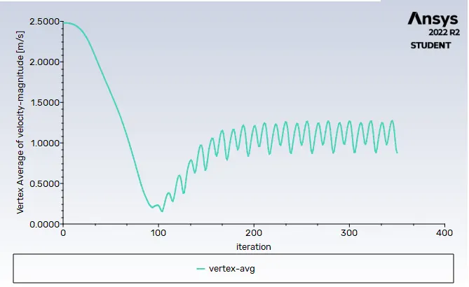
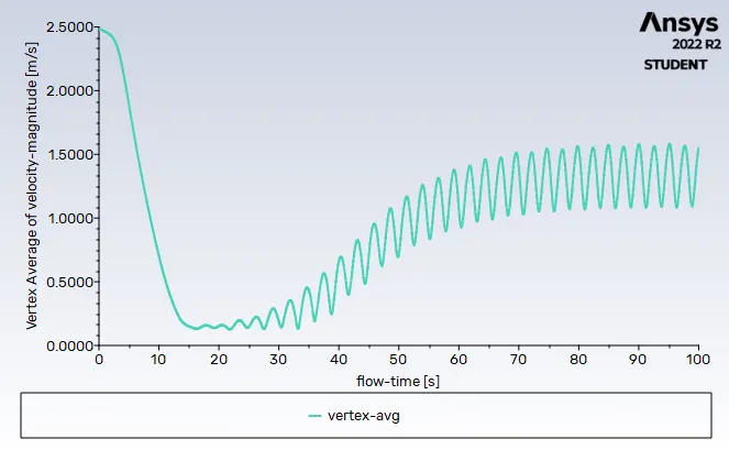
For steady state solver SIMPLE interpolation scheme will be used to calculate results in neighboring volume. Unsteady state simulation will be done using two interpolation scheme one is SIMPLE and other one is PISO with NITA. To check for convergence of solution we will create some plots which have vertex average velocity 8m behind the cylinder which will be used to plot strouhal number later using FFT option in FLUENT. After that lift coefficient and drag coefficient will be calculated on the cylinder wall.
To check for vorticity only in FLUENT we will create a custom function which called as Q-criterion this is the one of the way of qualifying the wake vortices. The formula for Q-criterion is given by:
`Q = (delU)/(delx)*(delV)/(dely)*(delU)/(dely)*(delV)/(delx)`
The Reynolds number calculation is done by given governing equation:
`Re = (VDrho)/mu`
Where,
Re = Reynolds number
ρ = Density of Fluid
V = Velocity of Fluid
D = Characteristic length in case of cylinder it is Diameter.
µ = Dynamic viscosity.
The coefficient of drag and lift are the function of respective lift and drag force with density of fluid and velocity with exposure area in front. The equation for coefficient of lift and drag is given as:
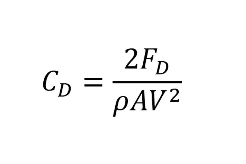
Where,
Fd and Fl are drag force and lift force respectively.
ρ = Density of Fluid
V = Velocity of Fluid
A = Frontal Area.
Case 1 :- Simulation of the flow over cylinder with the steady and unsteady case and calculate the Strouhal Number for Re= 100
This simulation involves both steady state solver and unsteady state solver. The solver will be pressure based for both simulations. The velocity required for calculation of Reynolds number of 100 is given as: ``Re = (VDrho)/mu``
Re = 100, D = 2, Density = 1, Viscocity = 0.05
SO, by calculating the equation we get Velocity = 2.5 m/s.
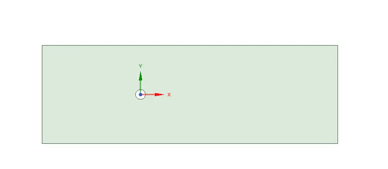
Geometry :-
Meshing :-
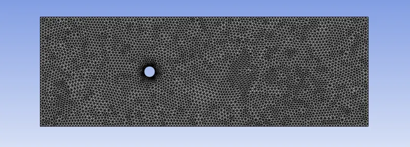
The meshing involves the creation of small discrete domain for calculation of governing equations. The mesh should be fine enough to compensate for every changes that will create during simulation. Mesh size which is used for the steady state and unsteady solver will be same which is 0.25m for overall domain. It is important to capture flow around cylinder as flow separation seizure. To capture the flow near cylinder the inflation layer is need to be used. Inflation will create hexahedral mesh near the cylinder which makes solution convergence and will provide accurate solution.
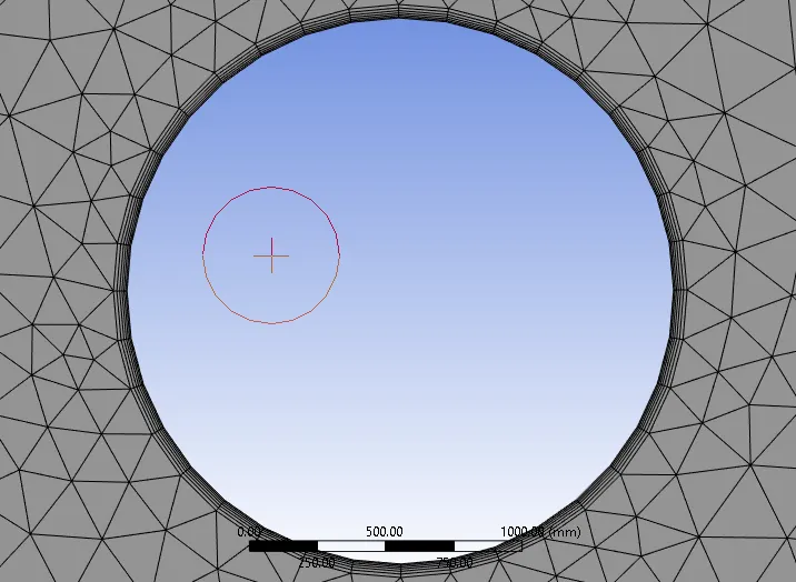
Before inflation layer creation it required to capture the boundary of cylinder by using edge sizing local meshing method. For edge sizing mesh size or number of layers can be used as user input. For this case mesh size near the boundary is taken as 0.01m. The inflation layer property is first layer thickness in which height of first layer is 0.05 and amount of layer are 9 for capturing more area near the cylinder with growth rate of 1.2. After applying this value to the geometry the mesh will look like:
Mesh near the cylinder ,, As we have used inflation layer 6
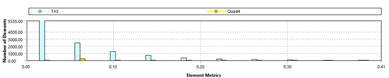
Quality criteria :-

Skewness :-
Material Selection: -
The fluid which is used for the simulation is air with constant density and constant dynamic viscosity. To get required Reynolds number only inlet velocity has been changed respectively. The properties of air are given below:
- Density of Fluid: - 1 kg/m^3.
- Dynamic Viscosity: - 0.05 kg/m-s
Solver setting: -
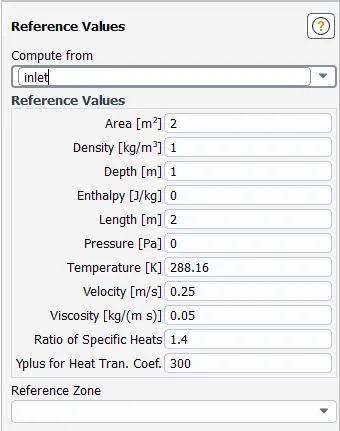
Result – Steady State Solver for Re = 100
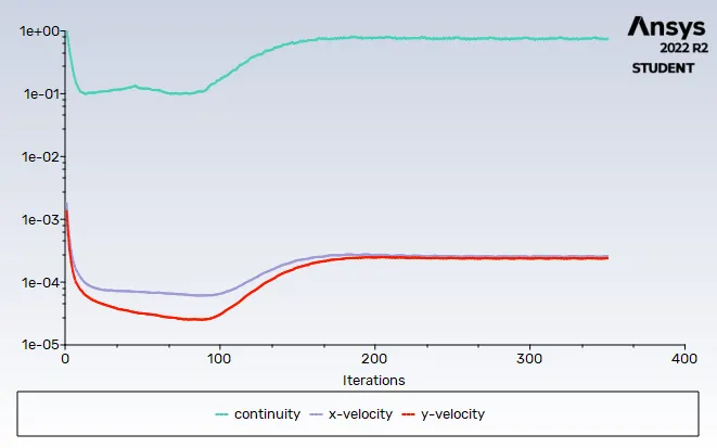
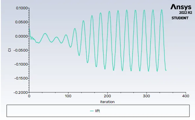
After initialization of solution we run the simulation for 350 iteration .
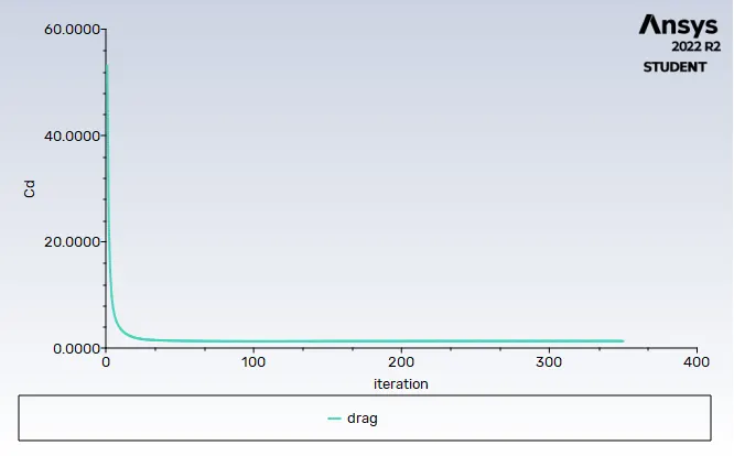
Drag coefficient
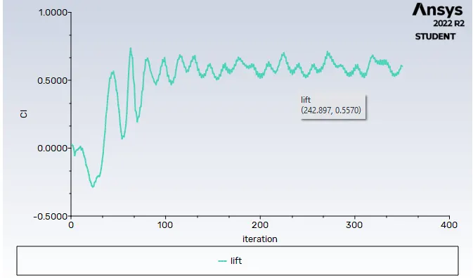
Lift coefficient
Vertex average
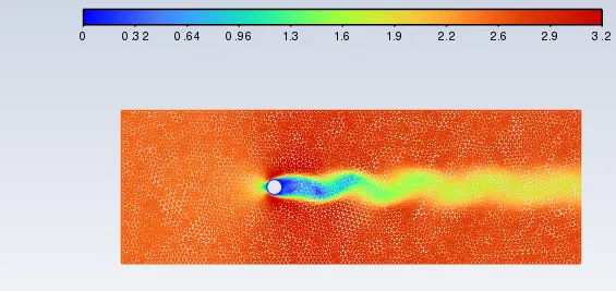
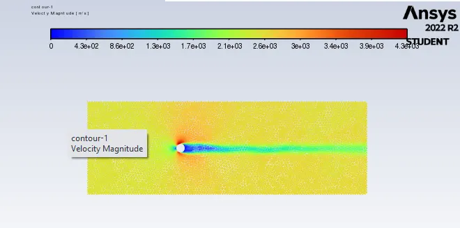
Velocity contour
Result – Unsteady State Solver for Re = 100
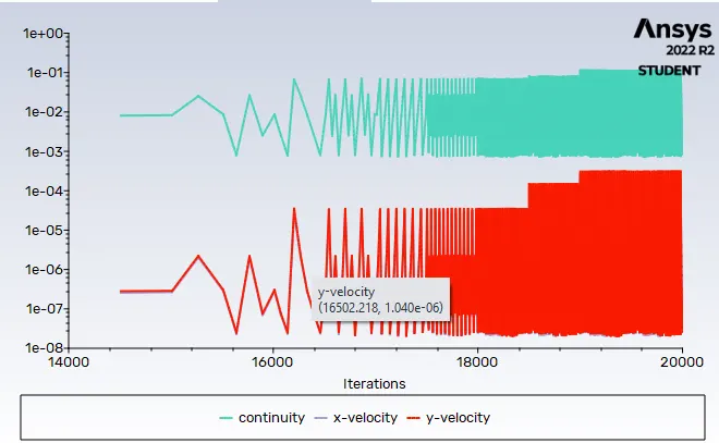
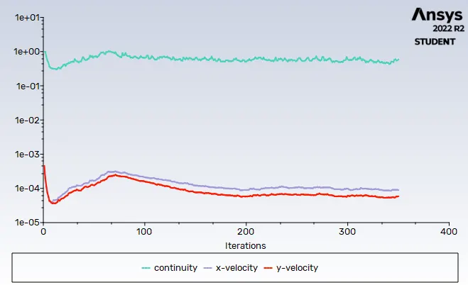
Residual
Drag coefficient
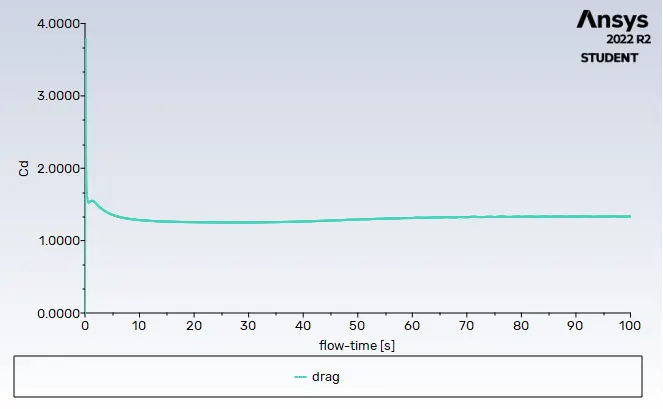
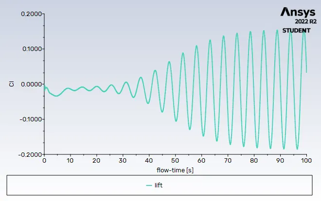
Lift coefficient
Vertex average
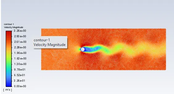
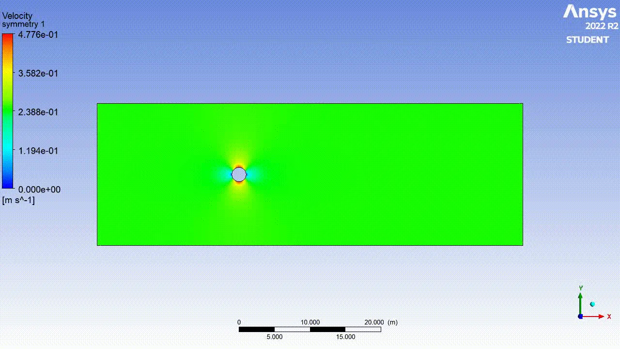
Velocity contour
5) Strouhal Number
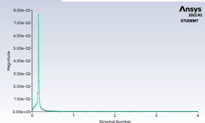
The strouhal number is calculated by going into plot option in FLUENT in which FFT option has to be choose. In FFT option Y axis function should be Magnitude and X axis function should be strouhal number. After that we need to provide the file of coefficient of lift from simulation and fed to the window to calculate the FFT of lift coefficient which further provide strouhal number.
Conclusion: -
- After running both the simulation respectively for steady state and unsteady state simulation it was found that unsteady state simulation provides the result near to the experimentation value validated from the research paper.
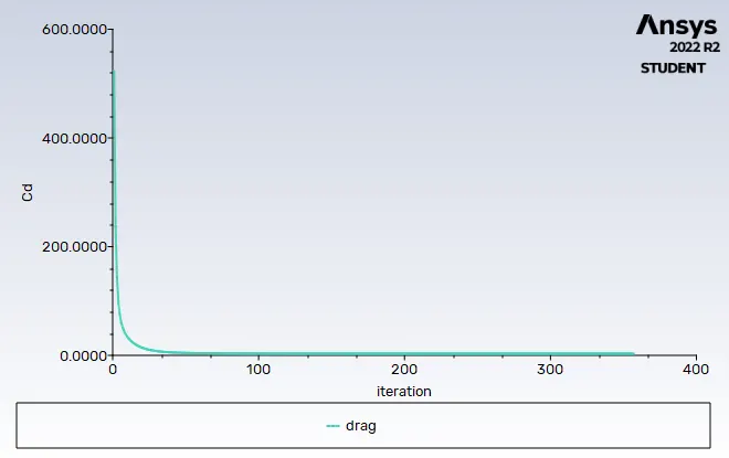
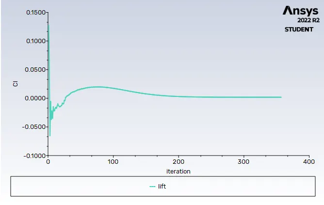
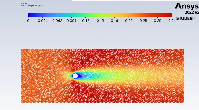
CASE – 2: - Simulation over cylinder with steady solver for Reynold number of 10,1000,10000,100000
For Re = 10 inlet velocity = 0.25 m/s
Drag coefficent
Lift coefficient
Velocity contour
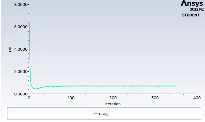
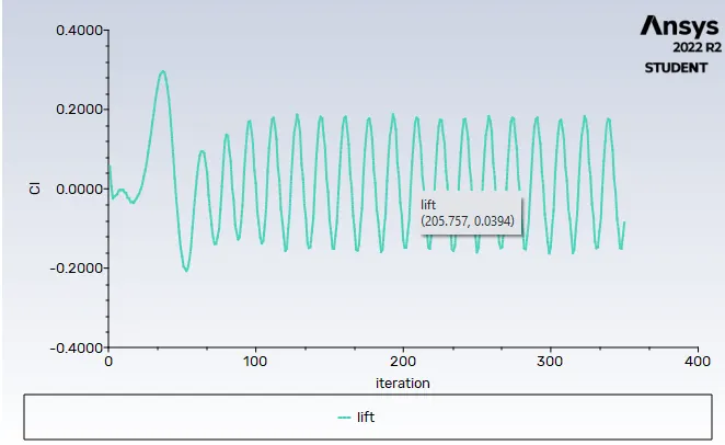
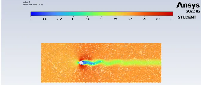
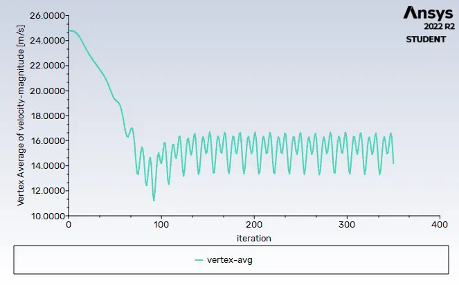
Re = 1000 inlet velocity = 25 m/s
Drag coefficient
Lift coefficient
Velocity contour '
Vertex average
Re = 10000
Drag coefficient
inlet velocity = 250 m/s
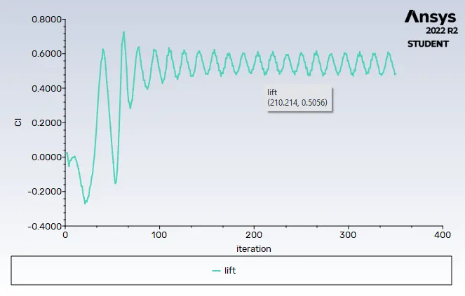
Lift coeffficient
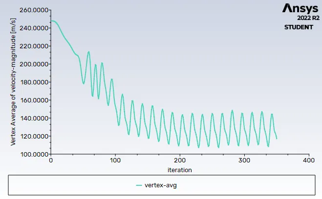
Vertex average
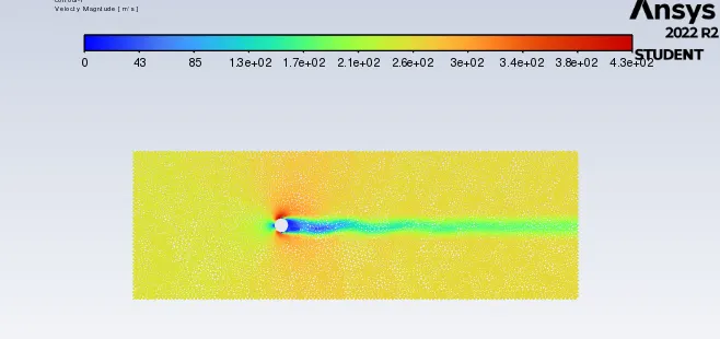
Velocity contour
Re = 100000 inlet velocity = 2500 m/s
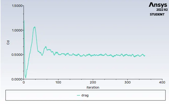
Drag coefficient
Lift coefficient
Residual plot
Velocity contour
Animation of velocity Contour for Re = 10
Re = 100
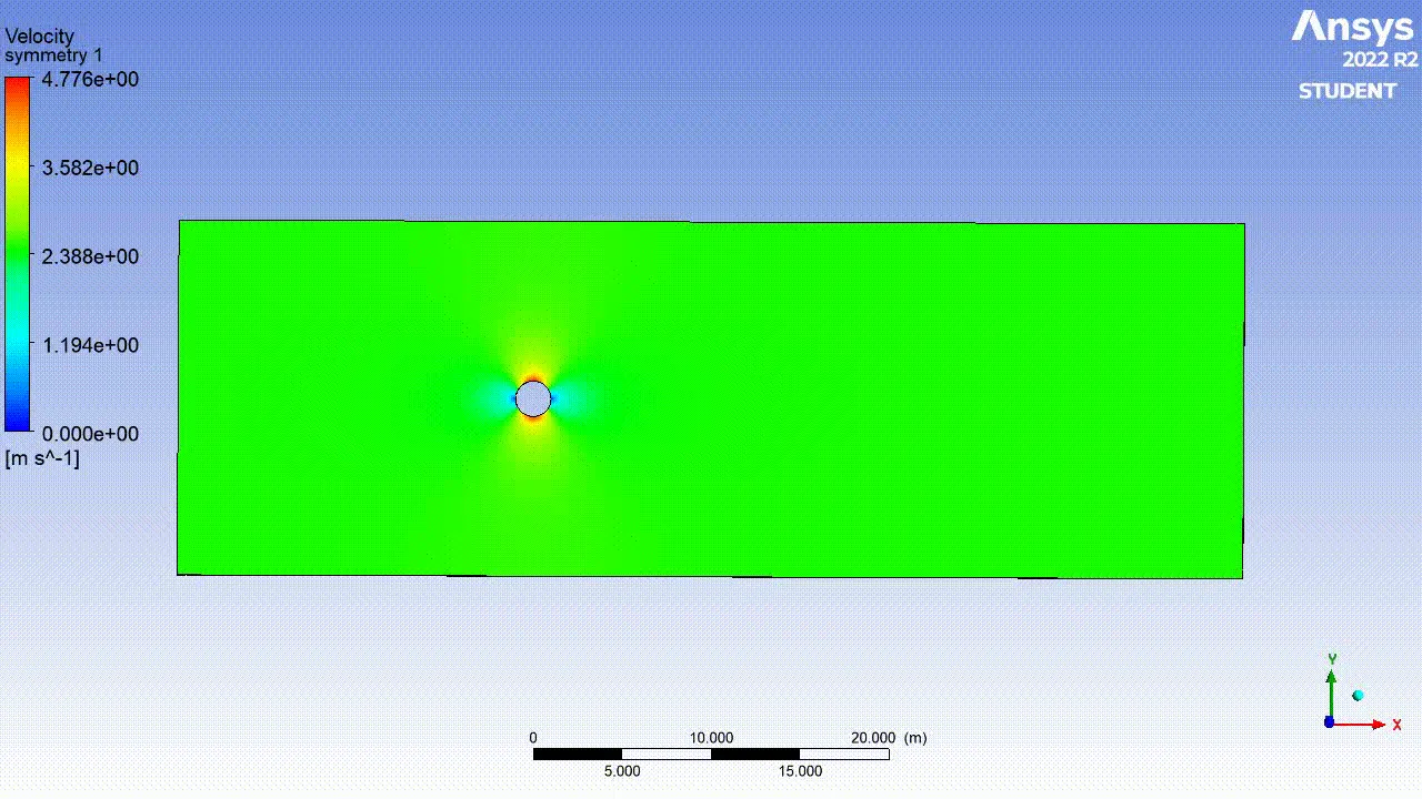
Re = 1000
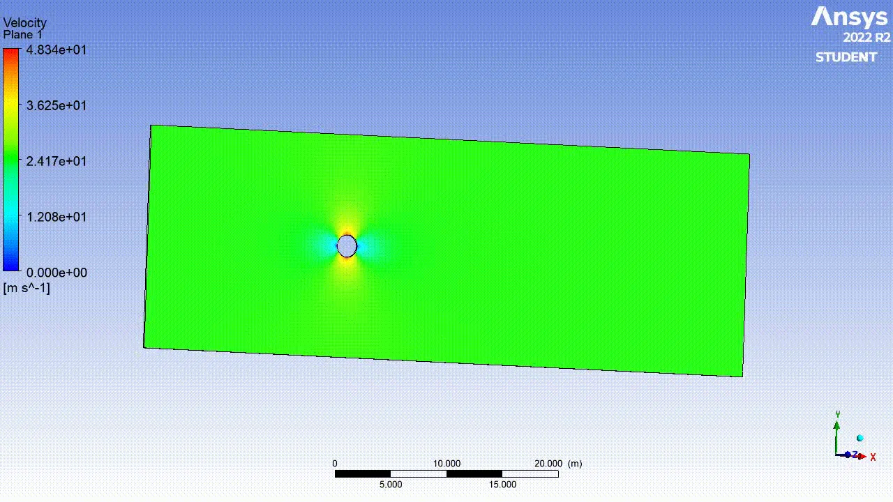
Re = 10000
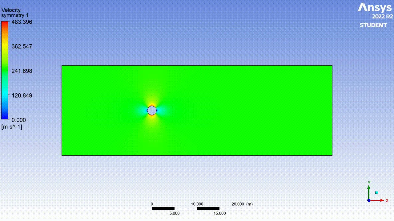
Re = 100000
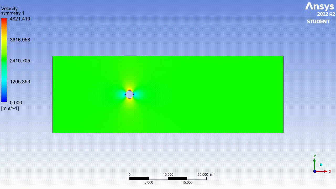
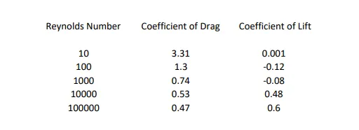
Comparison Table of Reynold number with Coefficient of Drag & Lift
Conclusion: -
1) If we compare the data in the table, it is seen that as Reynolds number is increasing the coefficient of Drag is decreasing and coefficient of lift is increasing.
This phenomenon is happening because of when Reynolds number get increased the surface friction between fluid and cylinder is also increasing which casue the boundary layer to break before flow seperated hence amount of drag get decreases and lift get increases.
2) As the Reynolds number increase in value the wake region behind the cylinder is also increasing which results in bigger domain capturization for further simulations.
3) For lower Reynolds number the vortices are bit symmetrical in nature but as Reynolds number get increase it start to deviate more.
References :-
https://www.sciencedirect.com/science/article/pii/S0307904X08000243
https://skill-lync.com/knowledgebase/how-to-create-an-animation-in-ansys-fluent