Week 2 - Flow over a Cylinder.
AIM:
Simulate the flow over a cylinder and to explain the phenomenon of Karman vortex street for the following cases
- To simulate the flow with the steady and unsteady case and calculate the Strouhal Number for Re= 100.
- To calculate the coefficient of drag and lift over a cylinder by setting the Reynolds number to 10,100,1000,10000 & 100000. (Run with steady solver)
- Discuss the effect of Reynolds number on the coefficient of drag. [ Results should be validated with any standard literature and error should be within 5 %]
EXPECTED RESULTS:
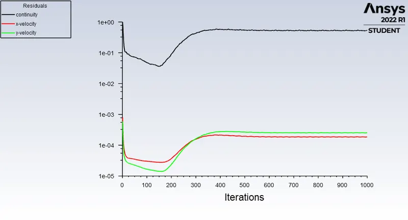
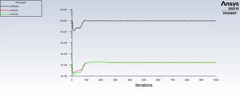
- In both approaches, to show that the flow has converged.To explain, what quantities or plots need to be looked at to determine that the flow has converged?
- Plots of the coefficient of drag and lift.
- Plots to show vortex shedding behind the cylinder.
DESCRIPTION:
VORTEX SHEDDING:
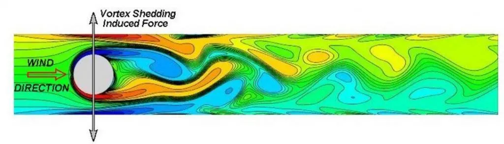
Vortex shedding is an oscillating flow that takes place when a fluid such as air or water flows past a bluff (as opposed to streamlined) body at certain velocities, depending on the size and shape of the body.In this flow, vortices are created at the back of the body and detach periodically from either side of the body forming a Von Karman Vortex street. The fluid flow past the object creates alternating low pressure vortices on the downstream side of the object. The object will tend to move forward the low pressure zone.
If the bluff structure is not mounted rigidly and the frequency of vortex shedding matches the resonance frequency of the structure, then the structure can begin to resonate, vibrating with harmonic oscillations driven by the energy of the flow.This vibration is the cause for overhead power line wires humming in the wind, and for the fluttering of automobile whip radio antennas at some speeds.Tall chimneys constructed of thin walled steel tubes can be sufficiently flexible that in air flow with a speed in the critical range, the vortex shedding can drive the chimney into violent oscillations that can damage and destroy the chimney.
REYNOLDS NUMBER:
Reynolds number for a flow is a measure of the ratio of inertial to viscous forces in the flow of a fluid around a body.
Re=`(rhoVd)/mu`
`mu` is the dynamic viscosity (Pa-s or N-s/m^2)
`rho` is the density of fluid (kg/m^3)
`V` is the velocity of fluid (m/s)
`d` is the linear dimension (m)
The range of Re values will vary with the size and shape of the body from which the eddies are being shed, as well as with the kinematic vescosity of the fluid. Over a large Re range (47<`Reunderset(d)`<10^5 for circular cylinders; reference length is d:diameter of the circular cylinder) eddies are shed continously from each side of the circle boundary, forming rows of vortices in its wake.
STROUHAL NUMBER:
In dimensional analysis, the strouhal number is a dimensionless number describing oscillating flow mechanisms.
For large strouhal number (order of 1) viscosity dominates fluid flow resulting in a collective oscillating movement of the fluid 'plug'.For low strouhal numbers (order of `10^(-4)`and below) the high speed, quasi-steady state portion of the movement dominates the oscillation. Oscillatin at intermediate strouhal numbers is characterized by the buildup and rapidly subsequent shedding of vortices.
The strouhal number is given as `St=(fD)/(U')`
where f is frequency of vortex
D is characteristic diameter of the cylinder
U' is fluid flow velocity
COEFFICIENT OF DRAG:
In fluid dynamics, the drag coefficient is a dimensionless quantity that is used to quantify the drag or resistance of an object in a fluid environment, such as air or water. It is used in the drag equation in which a lower drag coefficient indicates that the object will have a less aerodynamic or hydrodynamic drag. The drag coefficient is always associated with a particular surface area.
It is given as `Cd=(2.Fd)/(rho.u^2.A)`
where Fd is the drag force which by definition the force component in the direction of the flow velocity
`rho` is the mass density of the fluid
u is the flow speed of the object relative to the fluid
A is the reference area
COEFFICIENT OF LIFT:
It is a dimensionless coefficient that relates the lift generated by a lifting body to the fluid density around the body, the fluid velocity and an associated reference area. A lifting body is a foil or a complete foil bearing body such as a fixed wing aircraft. `Cunderset(L)` is a function of the angle of the body to the flow, its Reynolds number and its Mach number. It is given as
`Cunderset(L)` = `(L)/(qS)=(L)/(1/2rhou^2S)=(2L)/(rhou^2S)`
where L is the lift force
S id the revelent surface area and
q is the fluid dynamic pressure in turn linked to the fluid density and to the flow speed
GEOMETRY FOR FLOW OVER A CYLINDER:
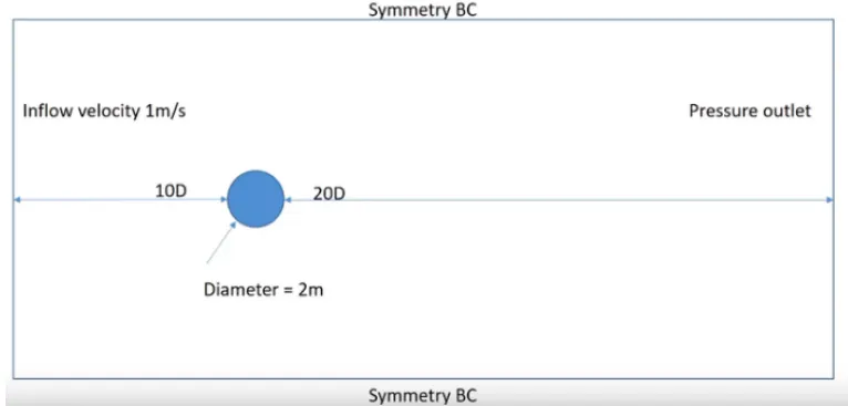
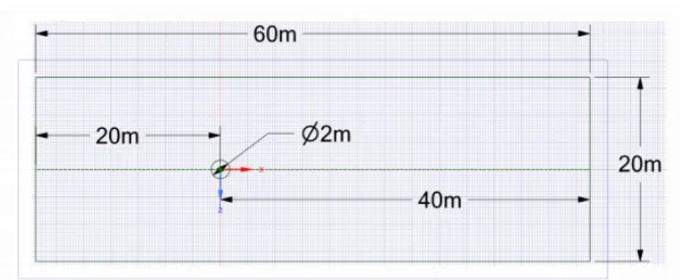
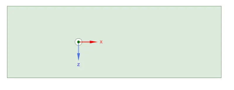
A plate with dimension of 20x60 m is created using spaceclaim, with a slice of cylinder along Y-axis with dia 2m as follows
MESHING:
A mesh is created for the geometry with elemental size of 0.25m as follows
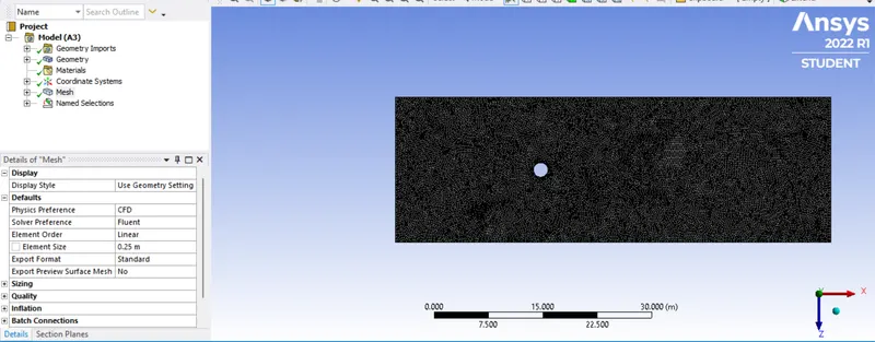
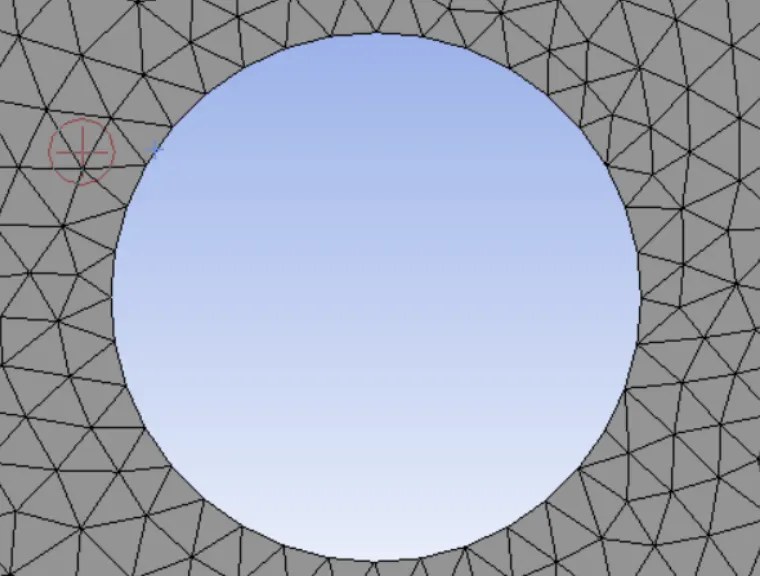
After generating the mesh it can be seen that the shape of the circle looks distorted. so for it to correct we to to mesh and select sizing>select circular edge>definition>type>no of divisions=36
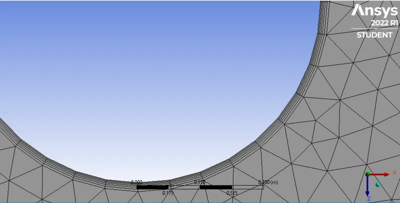
To capture the best results near the cylinder wall, we go to mesh>inflation>select the body and edge>inflation option:1st layer thickness>1st layer height as 5e-3>maximum layer:6
Now closing the mesh and moving forward.
FLUENT:
SOLVING:
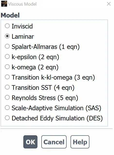
1.Select the laminar flow inside the viscous model.
2.As we wanted to customize material property for simulation, go to materials>fluent database> select the material (air)>copy it> rename the name of the material to user-defined.
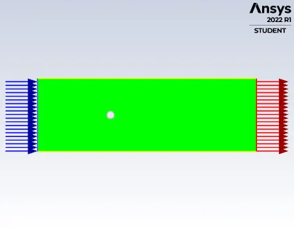

BOUNDARY CONDITIONS:
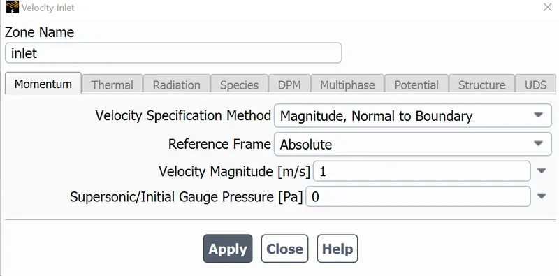
Defining for inlet as follows
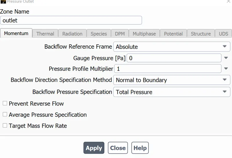
Defining for outlet as follows
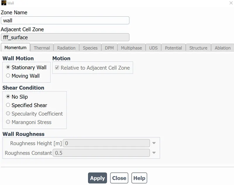
Defining the wall condition for no slip as follows
STEADY STATE SIMULATION:
1.REYNOLDS NUMBER 10
velocity = 0.25m/s
density = 1kg/m3
viscosity = 0.05 Pa-s
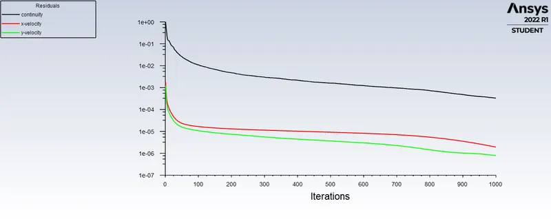
Residual plot is as follows
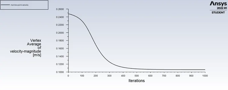
Monitor_point velocity:
A point is created at 4xdiameter=8m distance from the cylinder edge in x-direction.
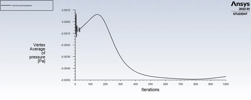
The pressure plot is as follows
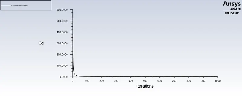
The coefficient of drag is 3.3300527
For lift coefficient is 0.00088450706
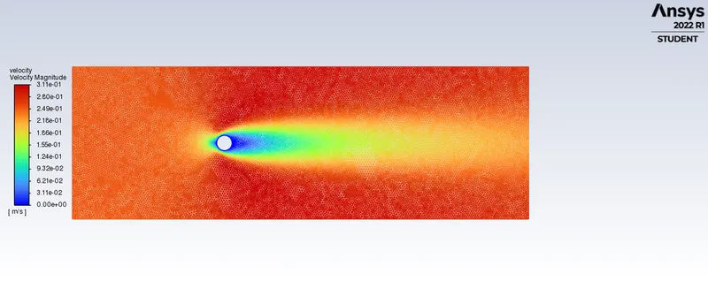
The veloctiy contour
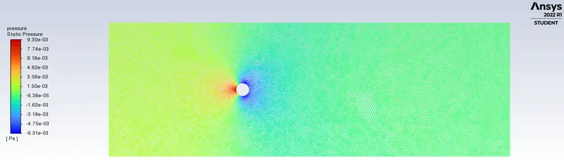
The pressure contour
2.REYNOLDS NUMBER 100
velocity = 2.5m/s
diameter = 2m
density = 1kg/m3
viscosity = 0.05 Pa-s
Residual plot is as follows
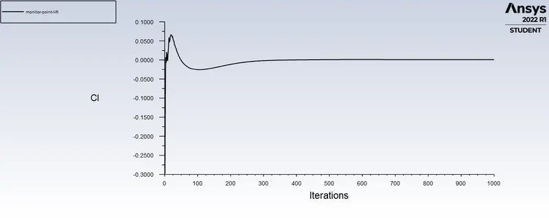
Monitor-point velocity at 8m in x-direction from axis of cylinder
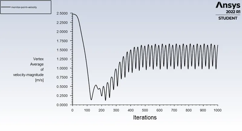
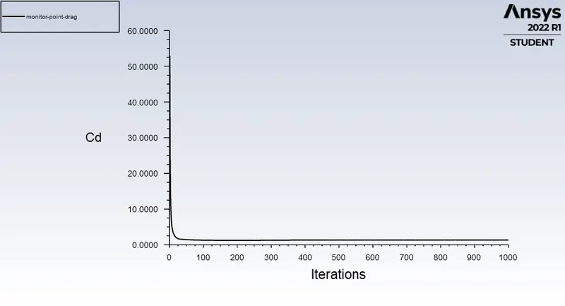
Coefficient of drag is 1.337642
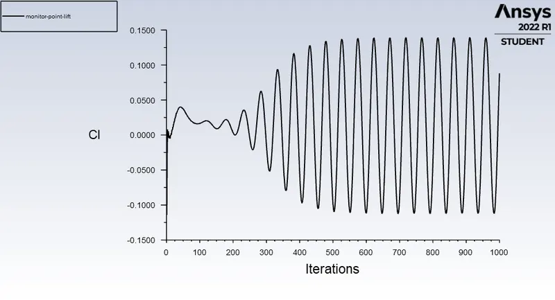
Lift coefficient is 0.088204106
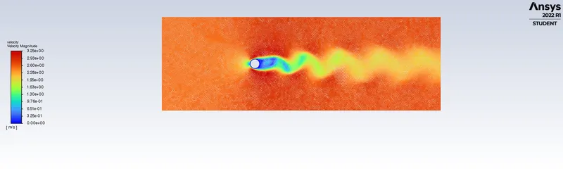
Velocity contour is
Pressure contour is
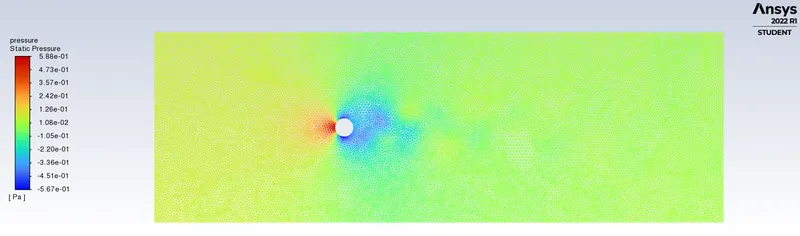
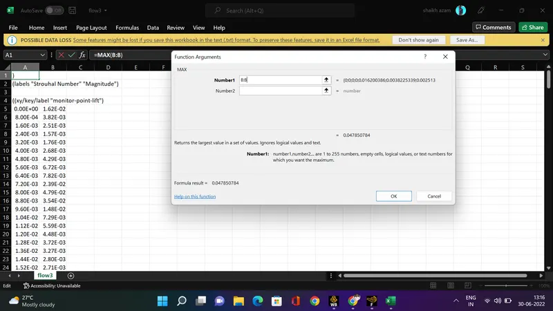
Strouhal number is 0.04785 for steady state with reynolds number 100.
3.REYNOLDS NUMBER 1000
velocity = 25m/s
density = 1kg/m3
viscosity = 0.05 Pa-s
Residual plot is as follows
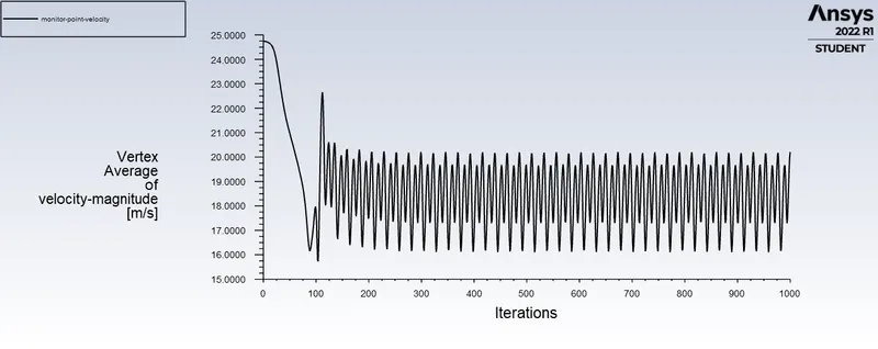
Monitor point velocity at 8m from axis of cylinder is
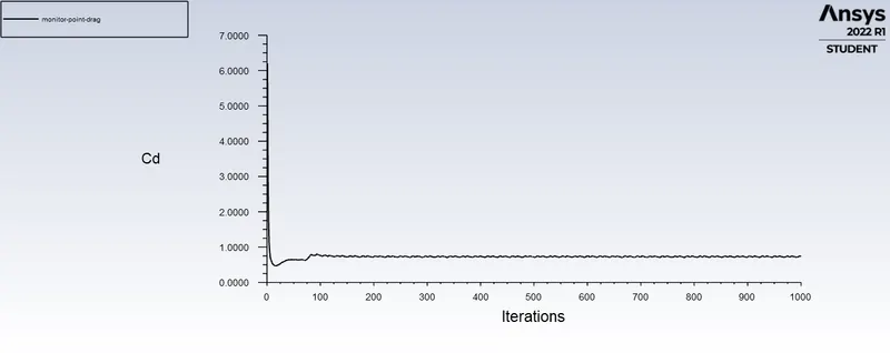
Coefficient of drag is 0.73004885
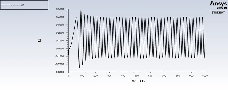
Lift coefficient is 0.20177613
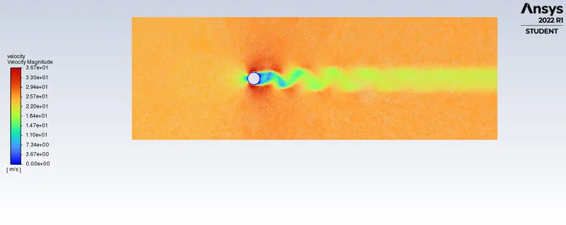
Velocity contour is
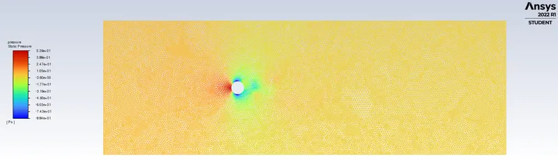
pressure contour is
4.REYNOLDS NUMBER 10000
velocity = 250m/s
density = 1kg/m3
viscosity = 0.05 Pa-s
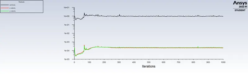
Residual plot is as follows
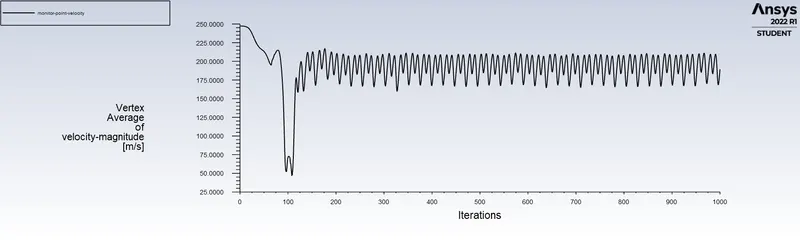
Monitor point velocity at 8m from axis of cylinder
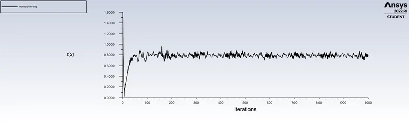
Coefficient of drag is 0.76857818
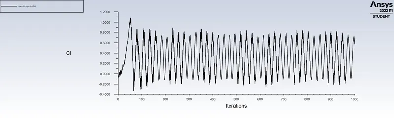
lift coefficient is 0.56977911
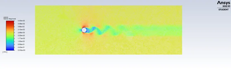
velocity contour is
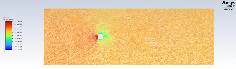
pressure contour is
5.REYNOLDS NUMBER 100000
velocity = 2500m/s
density = 1kg/m3
viscosity = 0.05 Pa-s
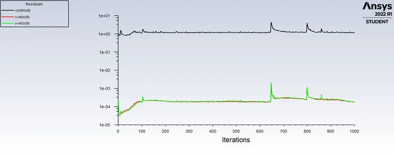
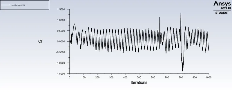
Residual plot is as follows
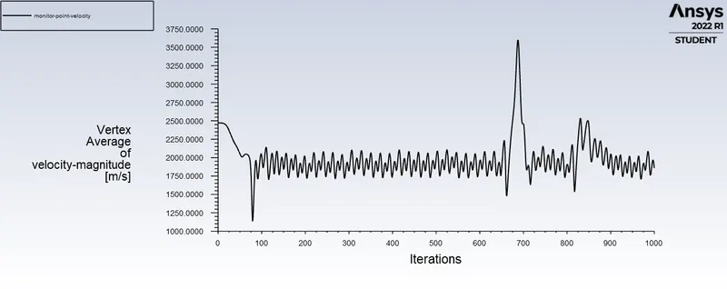
Monitor point velocity at 8m from axis of cylinder
Coefficient of drag is 0.61144579
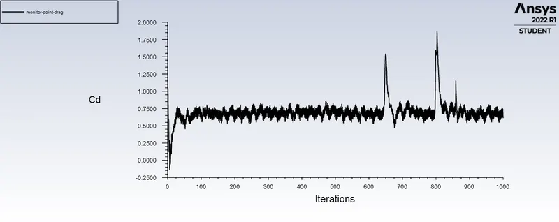
Lift coefficient is -0.43414601
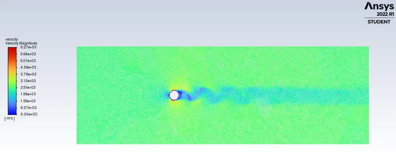
velocity contour is
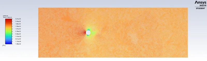
pressure contour is
UNSTEADY STATE SOLVER
REYNOLDS NUMBER 100
velocity = 2.5m/s
diameter= 2m
density = 1kg/m3
viscosity = 0.05 Pa-s
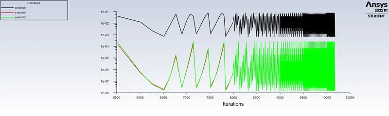
Residual plot is as follows
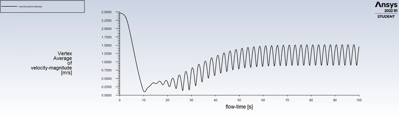
Monitor point velocity is
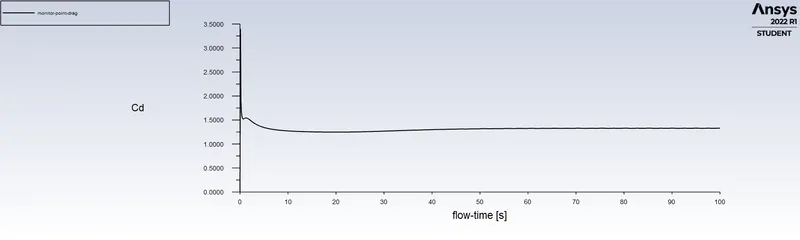
drag coefficient is 1.3304125
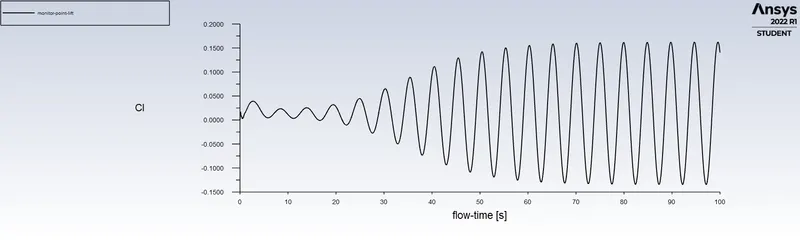
Lift coefficient is 0.14048435
velocity contour is
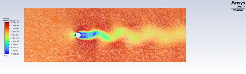
pressure contour is
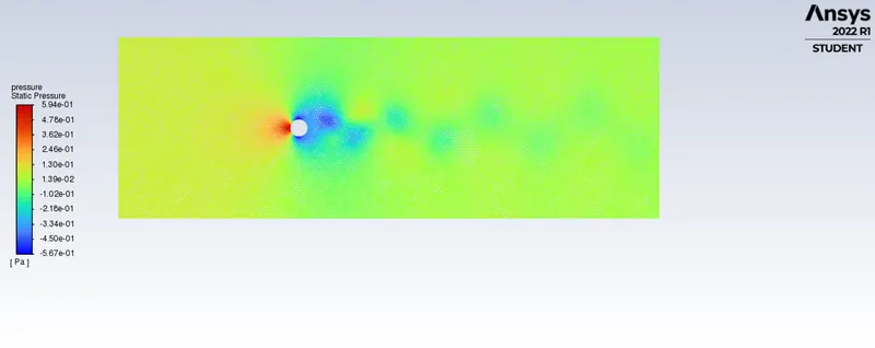
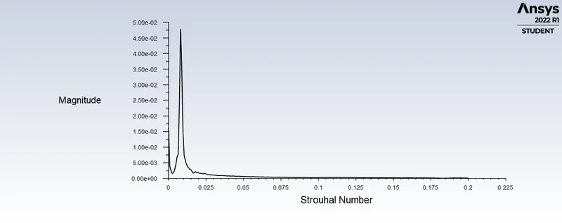
Strauhall number is a dimensionless number describing oscillating flow mechanisms.
It is given as f*d/u
Here we calculate as follows using ansys fluent
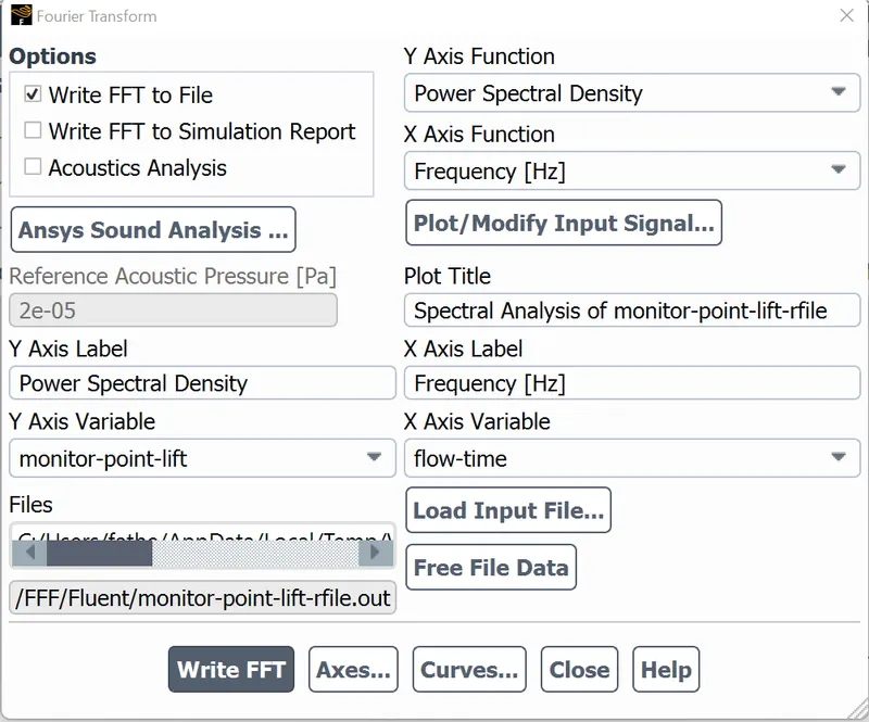
1.Go to fluent solver>results>fft analyser>load lift coefficient field>select plot FFT
Here x-axis denotes strauhal number and y-axis denotes magnitude.
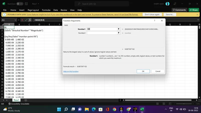
2.To get the magnitude of strauhal number
go to results>fft analyser>click on write fft to file>click on write fft.
Open the file in excel and 1st column denotes the frequency and 2nd column denotes strauhal number.Use the comand max and select the 2nd row and find the magnitude of strauhal number.
RESULTS:
FOR STEADY FLOW
| REYNOLDS NUMBER | DRAG COEFFICIENT Cd | LIFT COEFFICIENT Cl |
| 10 |
3.3300527 |
0.0008845 |
| 100 | 1.337642 | 0.0882 |
| 1000 | 0.73004885 | 0.20177613 |
| 10000 | 0.76857818 | 0.56977 |
| 100000 | 0.61144579 | -0.43414 |
Error w.r.t theoritical values from reference material
| REYNOLDS NUMBER | THEORITICAL Cd | NUMERICAL Cd | ERROR <5% |
| 10 | 3.5 |
3.3300527 |
4.85% |
| 100 | 1.4 | 1.33 | 4.45% |
CONCLUSION:
When fluid flows over cylinder, a wake region is formed next to the cylinder due to decrease in pressure and recirculation of flow occurs and hence flow separation occurs.
As flow over cylinder is being transient i.e time dependent we are unable to observe flow separation if reynolds number is <50.
In this challenge we have kept all parameters constant and have only varied velocity to change the reynolds number.So, as reynolds number increases coefficient of drag decreases. However, after reynolds number >4000 flow is turbulent and hence coefficient of drag is lower.
A strouhal number is 0.08759 for unsteady and 0.04785 for steady state with reynolds number 100 calculated for unsteady state with reynolds number 100 (velocity 1m/s density 1 viscosity 0.02 diameter 2m).