Week 2 - Flow over a Cylinder.
FLOW OVER A CYLINDER
INTRODUCTION
-In this project we are solving a flow over a cylinder which is a simulation of CFD , it is a very complex and challenging problem in fluid mechanics, where intensive investigations are continued even today to understand the complex unsteady dynamics of the cylinder wake flow .
-Cross-flow normal to the axis of a stationary circular cylinder and the associated problems of heat and mass transport are encountered in a wide variety of engineering applications.Both experimental measurements and numerical computations have confirmed the onset of instability of the wake flow behind a cylinder beyond a critical Reynolds number leading finally to a kind of periodic flow identified by definite frequencies, well-known in the literature as the Von Karman vortex street.
-In case of laminar flow past cylinders with regular polygonal cross-section, the flow usually separates at one or more sharp corners of the cross-section geometry itself, forming a system of vortices in the wake on either side of the mid symmetry plane. On the other hand, for a circular cylinder, where the point of flow separation is decided by the nature of the upstream boundary layer, the physics of the flow is much more complex than what its relatively simple shape might suggest.
-As the flow Reynolds number `Re = (rho*v*d)/(mu)` based on the free stream velocity (U), cylinder diameter (D) and kinematic viscosity ν of the fluid, changes from a creeping laminar flow value of the order of 0.1 to a turbulent flow of the Re of a million or even higher, variety of physical complexities start taking place.
-Steady laminar flow exists at Reynolds 40 ,Beyond a critical value of Re, depending on the other flow disturbances, a transverse oscillation sets in with loss of flow symmetry and vortices are shed from the cylinder surface.
OBJECTIVE-
-To set up case study state and unsteady state simulation on Ansys Fluent.
-Calculate the renolds number and its significance over cylinder flow.
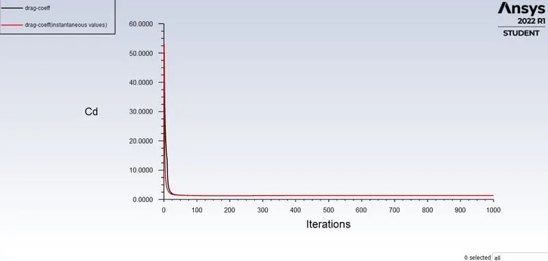
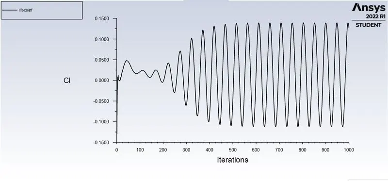
-Plots of the coefficient of drag and lift.
-Using Non-iterative time advacement method in which we lower the claculation time.
GOVERNING EQUATIONS
(1) Reynolds number
-It is the ratio of inertial forces to viscous forces. The Reynolds number is a dimensionless number used to categorize the fluids systems in which the effect of viscosity is important in controlling the velocities or the flow pattern of a fluid and also determine whether a fluid is in laminar or turbulent flow. it is mathematically defind as,
`Re = (rho*v*d)/(mu)`
In this equation , `rho=`Density of fluid
`v =`velocity of fluid
`d =`length of cylinder
`mu =` Kinematic viscocity
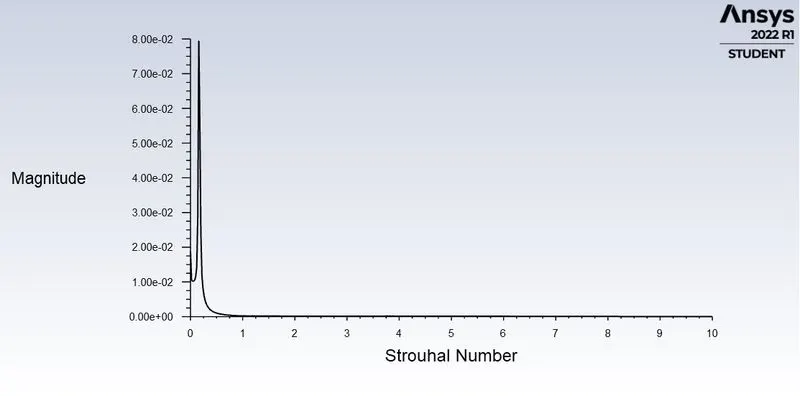
(2) Strouhal number
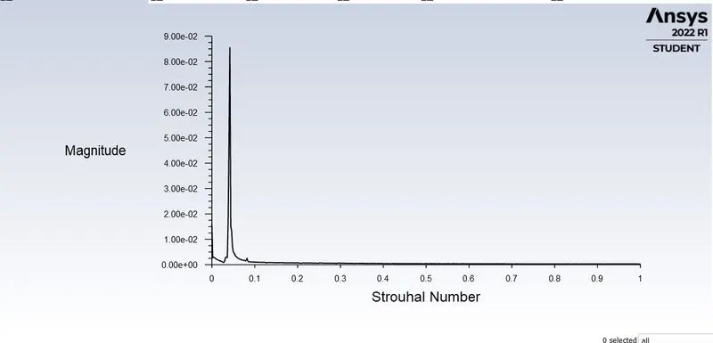
-The Strouhal number represents the ratio of inertial forces due to the local acceleration of the flow to the inertial forces due to the convective acceleratio`rho =`n.
`Sundersett`=`(fL)/v`
where f = frrequency of vertex shading
l = length
V = Fluid velocity
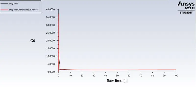
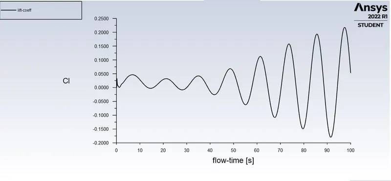
(3) Drag and lift force
-The functtion respective lift and drag force with density of fluid and velocity of fluid and velocity with exposure area in front.
-The equation for coefficient of lift and drag are as follow as,
`D = 1/2*rho*A*V^2.cundersetd`
where `rho =`fluid density
`v =`relative velocity
`A =`cross sction area of the body
`L = 1/2*rho*A*v^2*cundersetl`
where `v =`relative velocity
`A=`cross sectiion area of body
`rho =`fluid density
PROCEDURE
PART I-Simulation over cylinder with steady and unstedy solver (For Re=100)
-To stimulate , we have to follow some steps i.g Geometry setup , Meshing the model,solver setup.
Geometry setup-
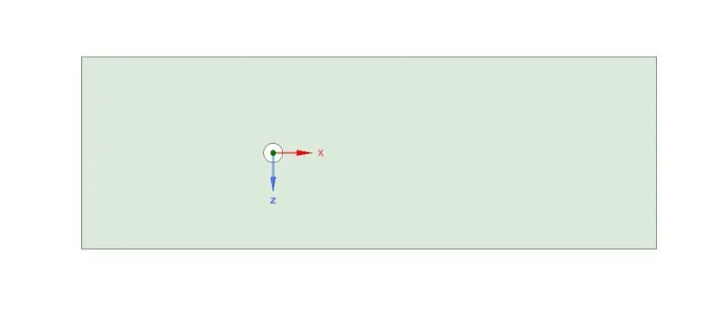
-In the above geometry is about 2m dia of the cylinder which is immeresed iside the domain of 20*60 m dimension.The inlet and outlet of the domain is 20,60m respectively from the center of the cylinder.
Mesh-
-The mesh involves the creation of small discrete domain the calculation of governing equation.The mesh should be fine enough to compensate for every changes that will create will change during that will create during simulation .
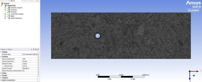
-The mesh near the cylinder is given below,
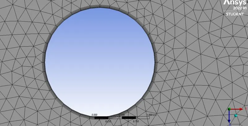
Mesh setup
- Meshtype - Triangular
- Element size-0.25
- No. of inflation layer-6
Solver setup
Boundary condition
- Inlet velocity-1m/s
- outlet pressure - 0 (i.e gauge presure)
- wall-no slip wall
Material used (i.e User-material)
- Reynolds number-100
- Density-1kg/m^3
- Viscocity-0.02 kg/m-s
Solver type
- Preaure based
- Transient/steady
solver model-laminar
POST-PROCESSING-
STEADY STATE SOLVER WITH SIMPLE VELOCITY COUPLING(RE=100)
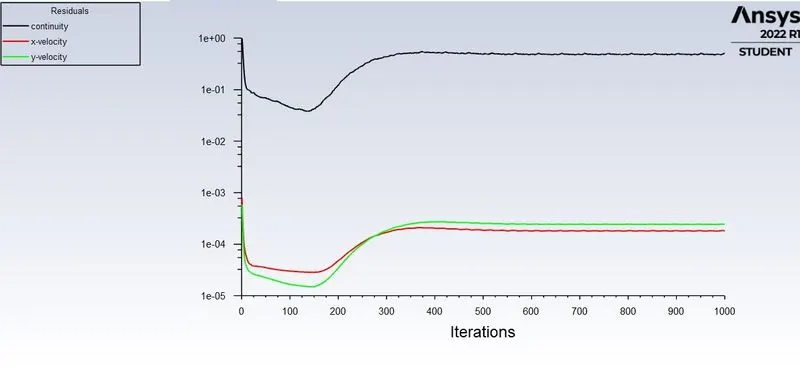
1-RESIDUALS
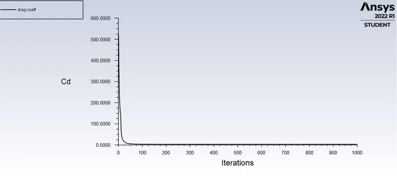
2-DRAG COEFFICIENT
3-LIFT COEFFICIENT
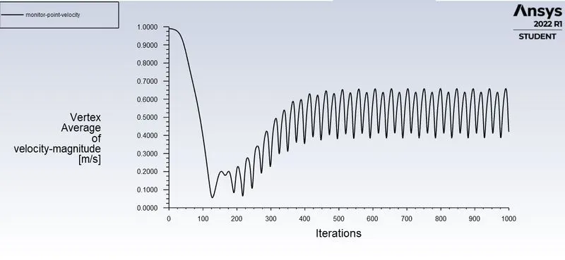
4-VERTEX AVERAGE-
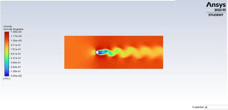
5-VELOCITY CONTOUR
STROUHAL NUMBER AND MAGNITUDE PLOT
ANIMATION-
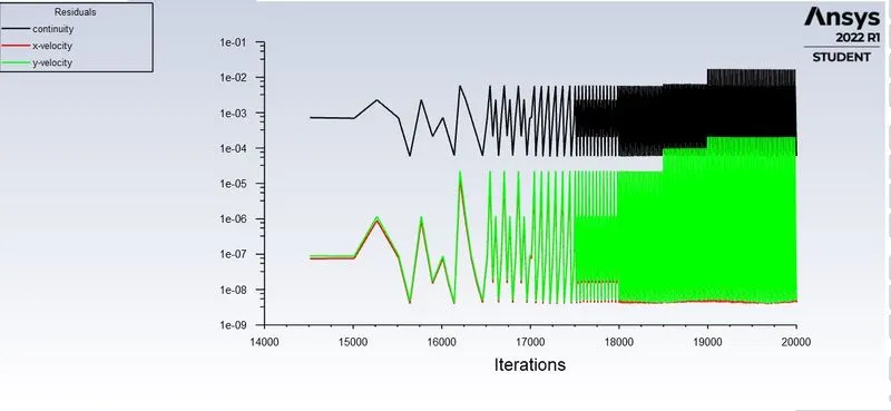
UNSTEADY(TRANSIENT) STATE SOLVER WITH RE=100
1-RESIDUALS
2-DRAG COEFFICIENT
3-LIFT COEFFICIENT
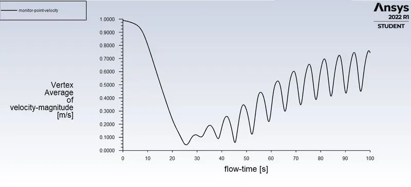
4-VERTEX AVERAGE-
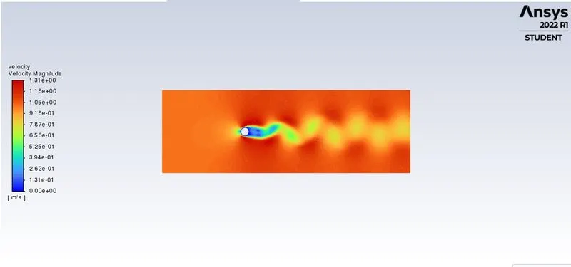
5-VELOCITY CONTOUR
STROUHAL AND MAGNITUDE PLOT
ANIMATION VIDEO
UNSTEADY(TRANSIENT) STATE SOLVER WITH NITA SOLVER(RE=100)\
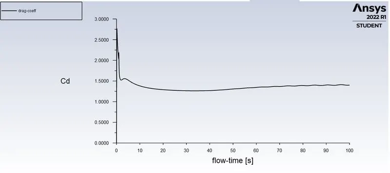
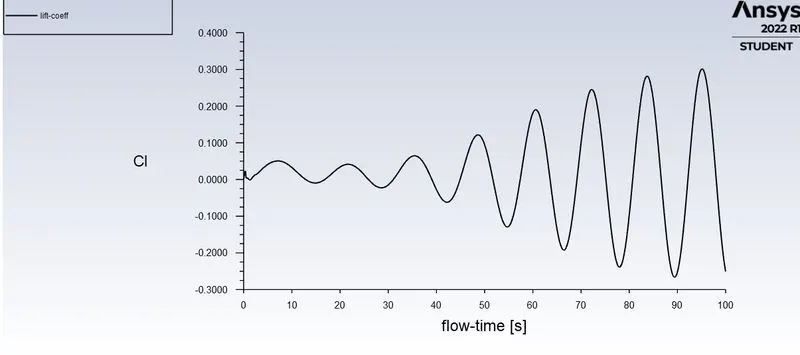
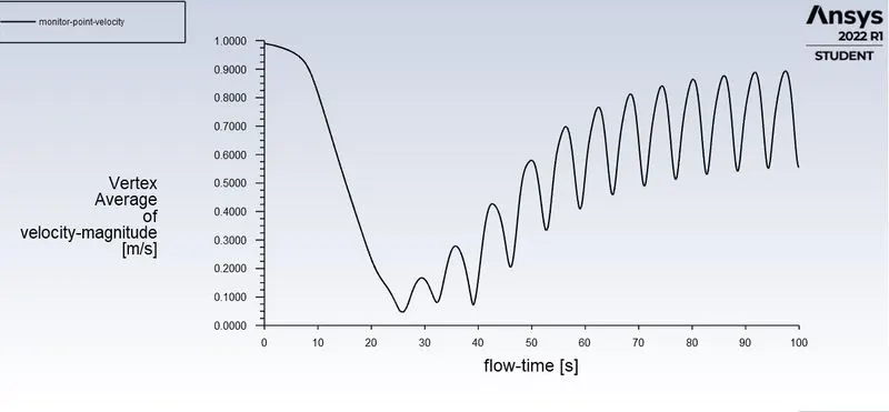
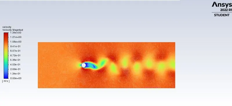
The Non iteratieve time advncement (NITA) solver is much faster with respect to simple pressure velocity coupling solver .In this method the transient formulation is selected as bounded second implicit which is 20% more faster.
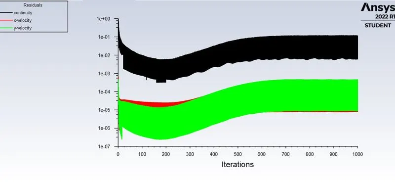
1-RESIDUALS
2-DRAG COEFFICIENT
3-LIFT COEFFICIENT
4-VERTEX AVERAGE-
5-VELOCITY CONTOUR
CONCLUSION
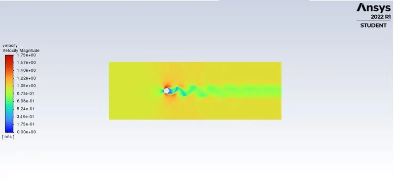
If we compare the velocity contour from both steady simulation and unsteady state simulatioin ,there was more realistic vortex generation is show in transient simulation as compare to steady state.Hence to capture the flow phenomenon effectively is more effective in transient solver.
PART II
Stimulation over cylinder with steady state solver for reynolds number of 10,100,1000,10000
Velocity contour
For Re -10
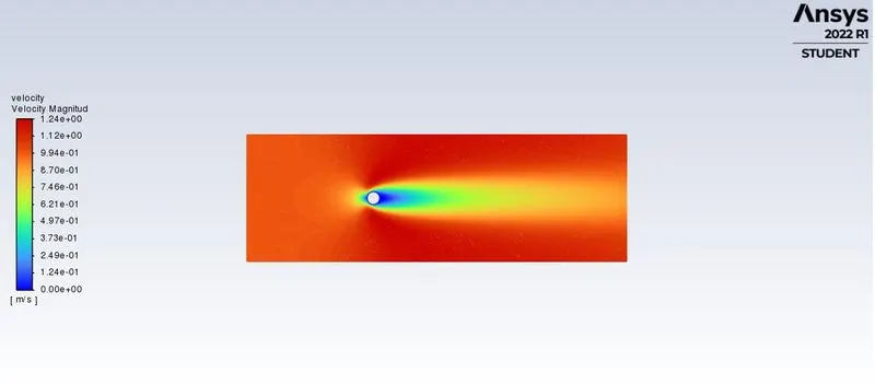
Re -100
Re-1000
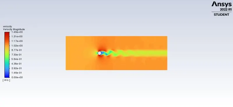
Re-10000
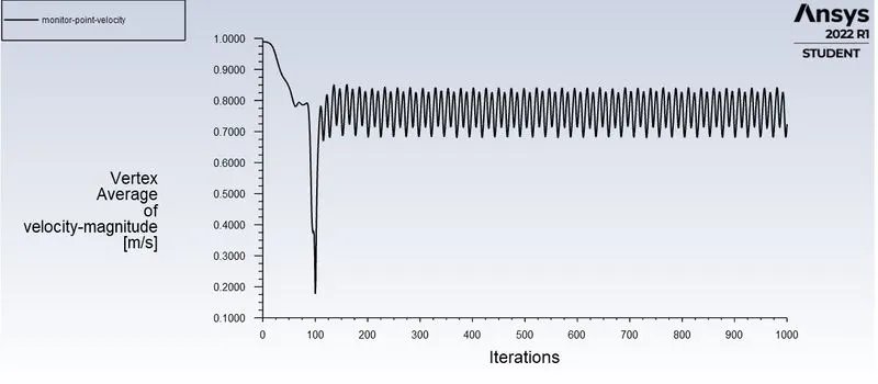
Vertex average
Re-10
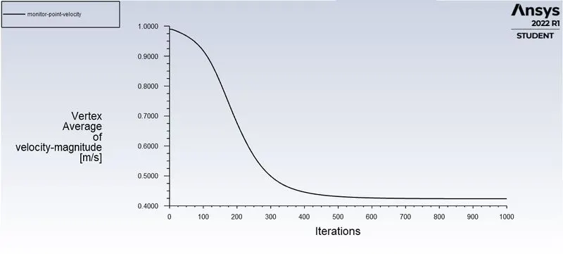
Re-100
Re-1000
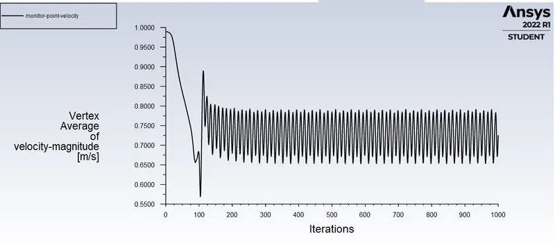
Re-10000
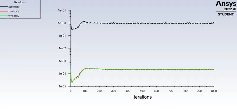
Residual plot for
Re-10
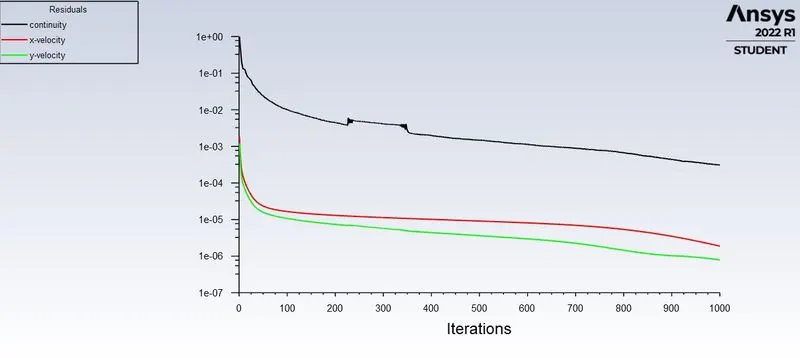
Re-100
Re-1000
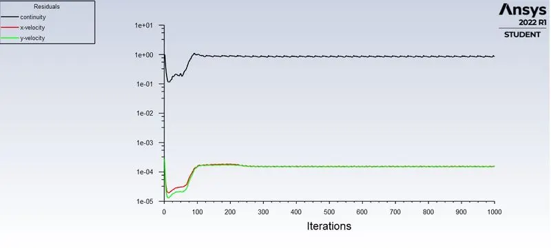
Re-10000
Drag coefficient
Re-10
Re-100
Re-1000
Re-10000
Lift coefficient for
Re-10
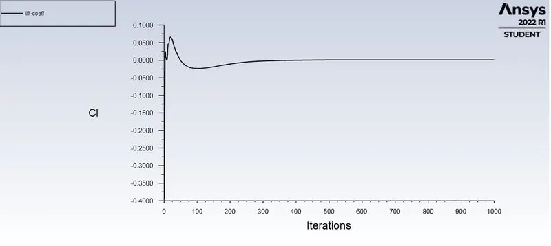
Re-100
Re-1000
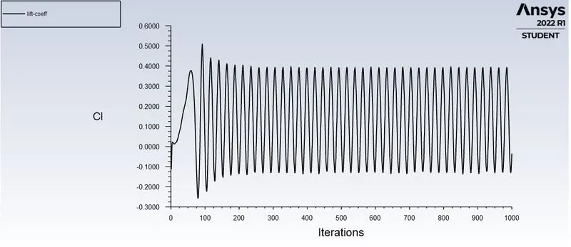
Re-10000
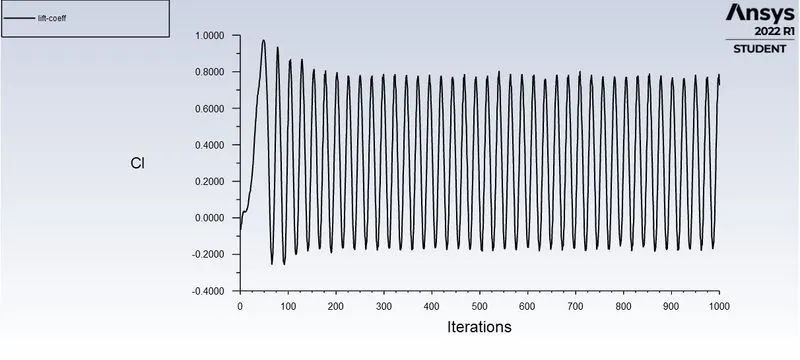
CONCLUSION
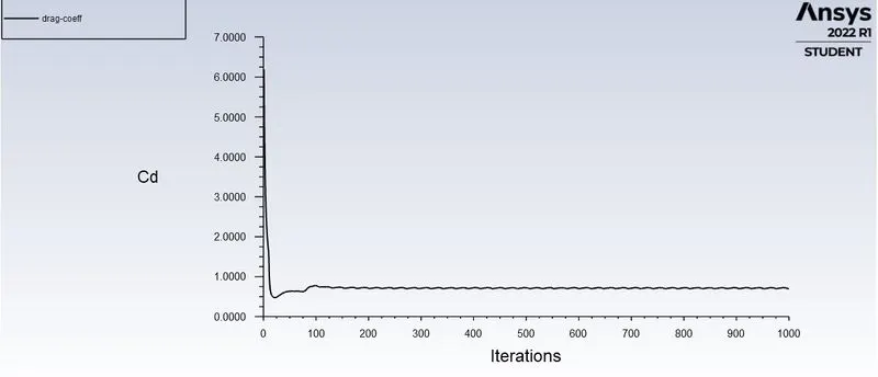
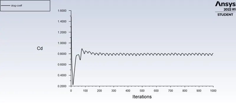
The Reynolds number expresses the ratio of inertial forces to viscous forces and skin frction drag depends directly on viscous interaction of the object and the flow .so every time increase or decrease in Reynolds number will affect drag and its coefficient, in the above we saw that if we increased drag coefficient we can see drag coefficient is decrese with incresing Reynolds numbeer except last case.
FRGG
TTTTEERR