Week 2 - Converging diverging nozzle
Objectives:
- To simulate the flow inside a converging diverging nozzle.
- To plot the pressure, temperature and density variation inside the nozzle
- To plot the variation of Mach number inside the nozzle , and find out at what distance the the flow becomes supesonic.
Introduction:
A de Laval nozzle (or convergent-divergent nozzle, CD nozzle or con-di nozzle) is a tube that is pinched in the middle, making a carefully balanced, asymmetric hourglass shape. It is used to accelerate a hot, pressurized gas passing through it to a higher supersonic speed in the axial (thrust) direction, by converting the heat energy of the flow into kinetic energy. Because of this, the nozzle is widely used in some types of steam turbine and rocket engine It also sees use in supersonic jet engines.
Assumptions:
- The gas flow is ideal
- The gas flow is isentropic
-
Methodology:
The methodology of the simulation is as follows:
- Geometry creation in Ansys space claim
- Mesh generation
- Fluent set up
- Post processing in CFD post
1) Geometry :
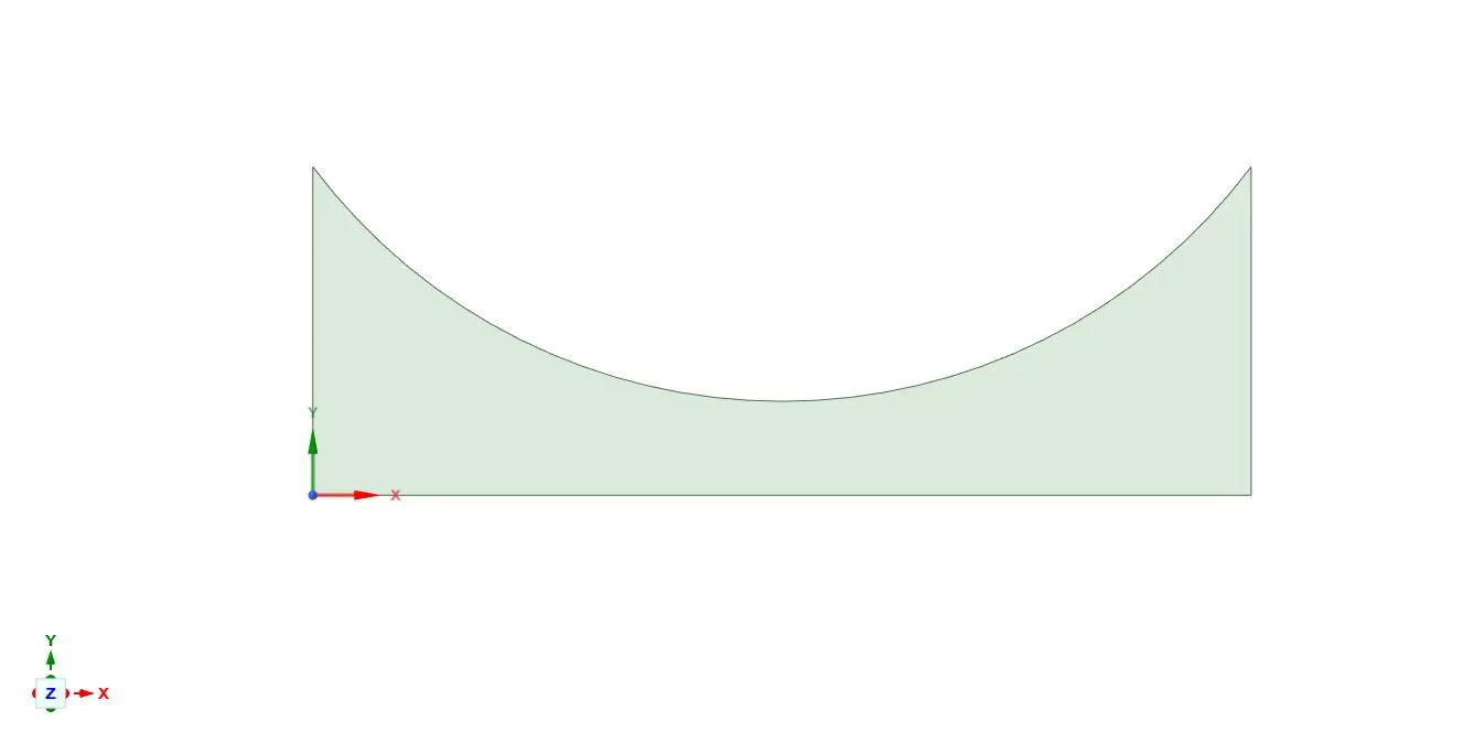
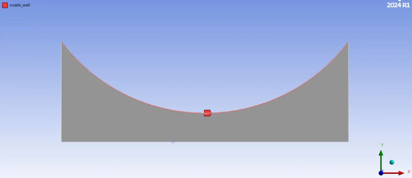
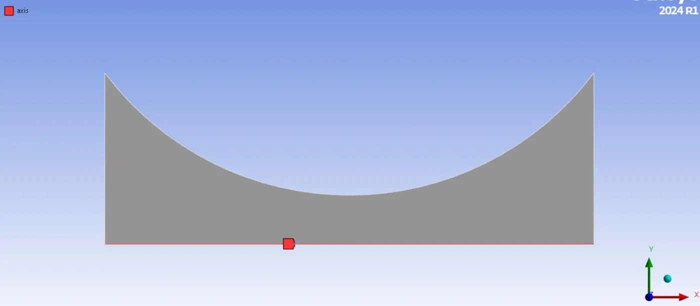
By opening Ansys space claim, The converging diverging nozzle is created , with the floowing dimensions. Since this is axisymmetric, the top half of the nozzle is prepared only to save the computational time.
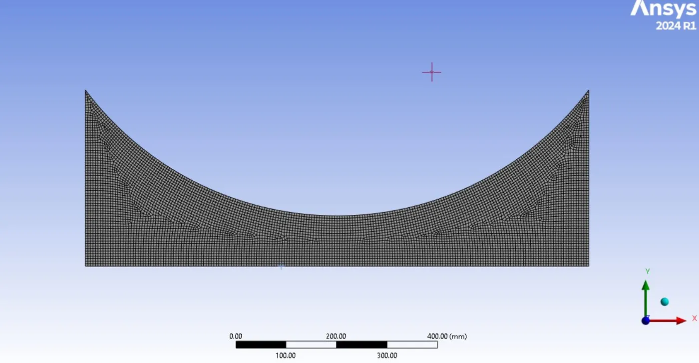
- Mesh : Element size (5mm)
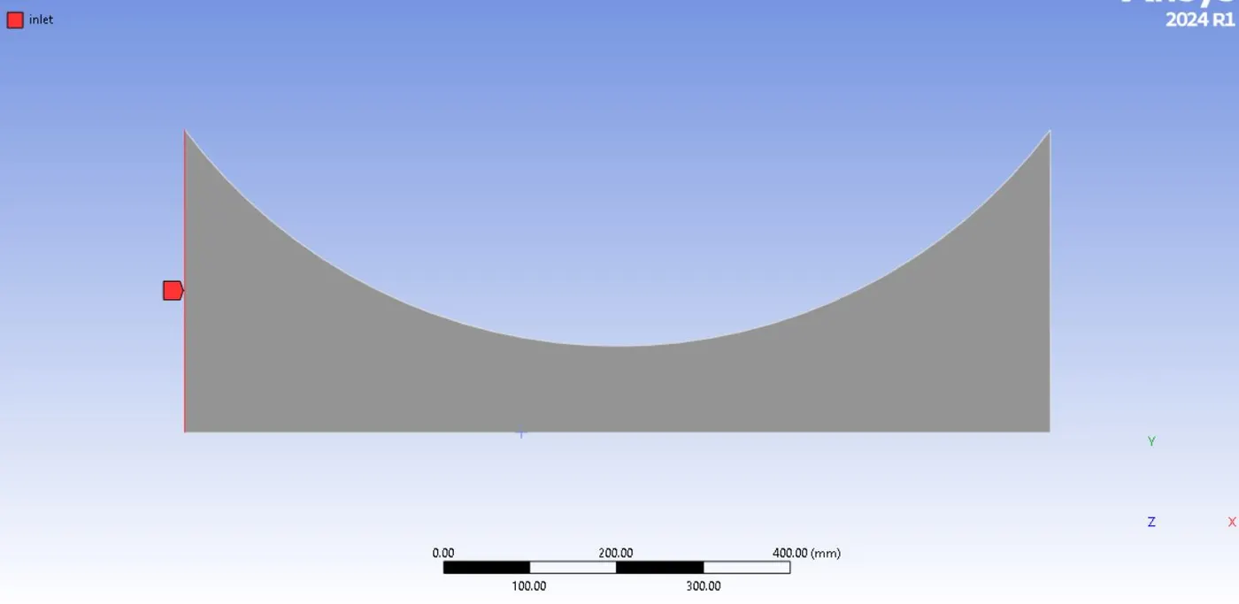
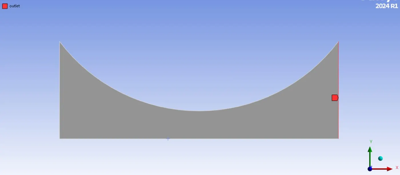
- Named Zones
-
3) Fluent set up:
- Checking mesh and evaluation mesh quality:
This can be done once the meshed model is loaded in fluent. If there is any error, it is popped up in the console.
- Operating conditions:
In this section , the reference pressure is set to zero. This is because, only absolute pressure is considered in the simulation.
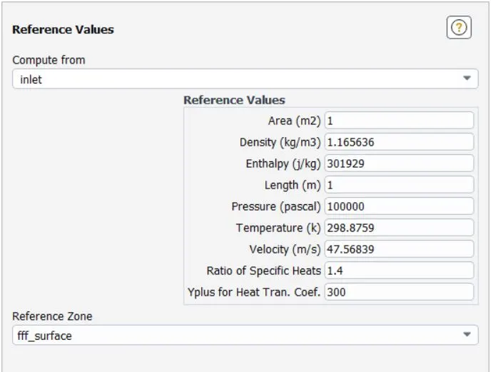
- Reference conditions:
For the reference coindition, the flow parameters are calculated from inlet.
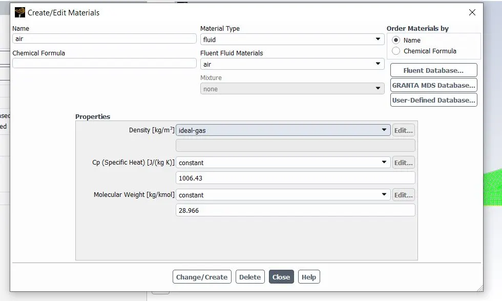
- Material selection:
Ansys fluent offers a wide variety of materials for the users to choose from. In this case, ideal gas is used.
- Physics set up:
1) energy is turned on, since temperature values are fluctuationg in the flow.
2) Inviscid flow is selected, since ideal gas is dealt with .
- General settings:
1) Density based solver is used.
Density based solver calculate their time step based on the accoustic time scale. For low mach number flows , speed of sound is pretty high, so to instill stability of the solver , a very low time step is needed leading to extremely high computational cost.
The density-based solver solves the governing equations of continuity, momentum, and (where appropriate) energy and species transport simultaneously (i.e., coupled together). Governing equations for additional scalars will be solved afterward and sequentially (i.e., segregated from one another and from the coupled set) . Because the governing equations are non-linear (and coupled), several iterations of the solution loop must be performed before a converged solution is obtained.
the steps are:
1. Update the fluid properties based on the current solution. (If the calculation has just begun, the fluid properties will be updated based on the initialized solution.)
2. Solve the continuity, momentum, and (where appropriate) energy and species equations simultaneously.
3. Where appropriate, solve equations for scalars such as turbulence and radiation using the previously updated values of the other variables.
4. When interphase coupling is to be included, update the source terms in the appropriate continuous phase equations with a discrete phase trajectory calculation.
5. Check for convergence of the equation set.
For the implicit method: For a given variable, the unknown value in each cell is computed using a relation that includes both existing and unknown values from neighboring cells. Therefore each unknown will appear in more than one equation in the system, and these equations must be solved simultaneously to give the unknown quantities.
2) Steady state simulation is done
3) Axisymmetric domain is used
4) graviation is not turned on, since the flow is horizontal.
- Boundary conditions:
1) Inlet:
Bounadry type : Pressure inlet.
Gauge total pressure is specified for the inlet.
Gauge pressure = 101325 pas
Inotial supersonic/gauge pressure is 100000 Pa.
Temperature at the inlet is 300K
2) Outlet:
Boundary type: Pressure outlet
Gauge pressure is 2735 Pas.
Back flow total temperature =300K
3)Nozzle wall:
Wall bpundary conditions are prevalent
4) Axisymmetric edge:
Symmetry boundary condition exist.
- Residuals:
The convergence criterion is set to 1e-06
- Hybrid initialiozation is done
- Contours and plots:
-
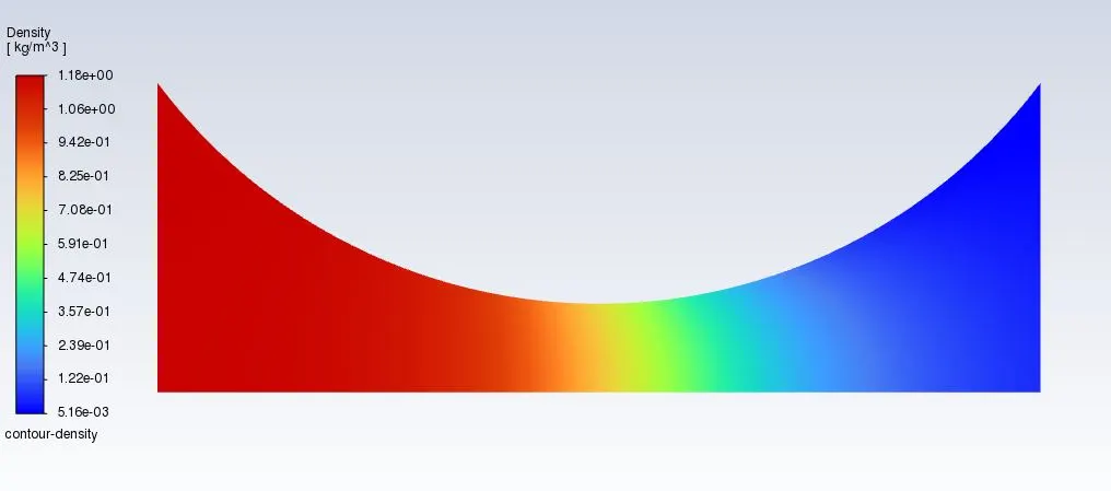
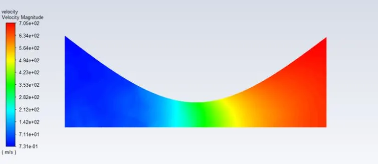
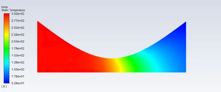
1) Contours of temperature, pressure, velocity and density is created along the nozzle.
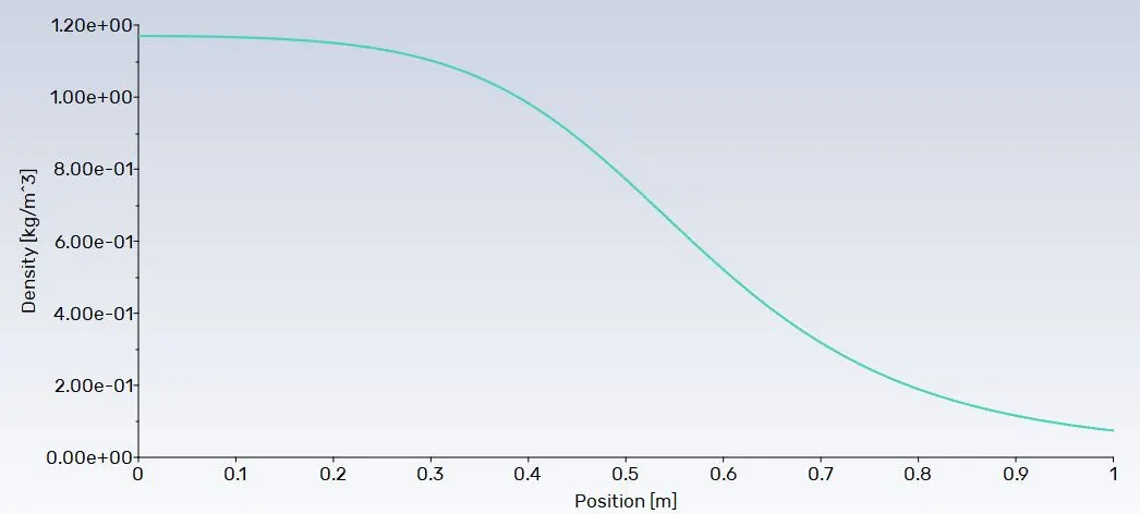
2) in the data files, xy plots are added, along the x axis, direction vector is plotted. Along the Y axis, mach number, density, pressure, Temperature is plotted along the axi symmetric edge. With this plots, the variation of these parameters along the nozzle can be monitored. This is particularly important for the validation of the results part.
- The simulation is run for 500 iterations
4) Solution:
The simulation is run for 5000 iterations:
- Density Contour
- Velocity Contour
- Temperature Contour
- Plots:
-
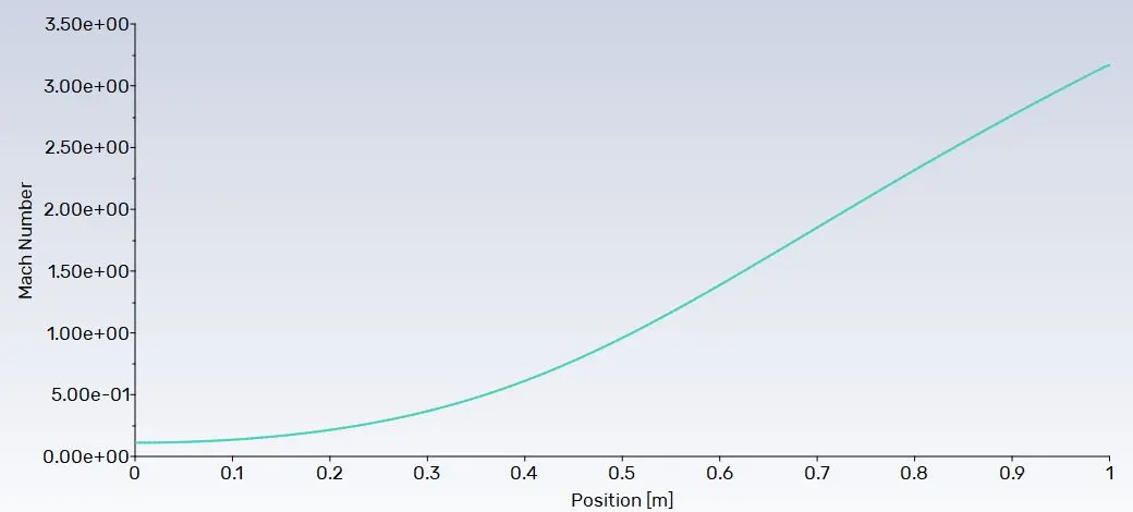
At inlet the Mach number is less than 1, this means at the inlet, the flow is subsonic. The flow changes from subsonic to supersonic at a certain distance from the inlet.
Supersonic flow is when the Mach number is 1.2 or more and less than 6. In the above plt, the mach number reaches 1, at an distance of 0.5 meters from the inlet.
Analytical discussion:
-
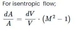
M is the mach number.
-
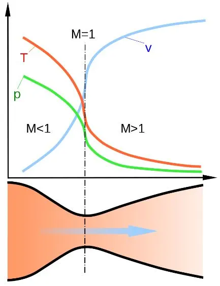
For the converging diverging nozzle, In the converging section, the area decreases towards the throat. So, the term dA��is negative. the term AV�� is always positive. So if we keep M2−1�2-1 is the RHS , and the other terms in the LHS. The term M2−1�2-1 is essentially negative.
1−M21-�2is positive.
Since, M�cant be 0, M� is less than 1.
This is particularly called the diffusor effect.
For the diverging section, similarly, the dA�� is positive. The change in velocity is positive . The mach number is eesentially more than 1. So the flow regime is supersonic. A sharp shock appaers when the flow region changes from subsonic to supersonic .
- For subsonic flow at the inlet, (M<1), a converging duct is always made to have the nozzle effect or to have the velocity incrteased.
- For supersonic flows, (M>1.2) , a diverging duct is made to have the nozzle effect.