Air standard Cycle
AIM: Write a program for otto cycle and plot a p-v diagram and also calculate the thermal efficiency.
THEORY: An Otto cycle is an idealized thermodynamic cycle that describes the functioning of a typical spark ignition piston engine. It is the thermodynamic cycle most commonly found in automobile engines. The Otto cycle is a description of what happens to a mass of gas as it is subjected to changes of pressure, temperature, volume, addition of heat, and removal of heat. The mass of gas that is subjected to those changes is called the system. The system, in this case, is defined to be the fluid (gas) within the cylinder. By describing the changes that take place within the system, it will also describe in inverse, the system's effect on the environment. In the case of the Otto cycle, the effect will be to produce enough net work from the system so as to propel an automobile and its occupants in the environment.
The Otto cycle is constructed from:
- Top and bottom of the loop: a pair of quasi-parallel and isentropic processes(frictionless, adiabatic reversible).
- Left and right sides of the loop: a pair of parallel isochoric processes(constant volume).
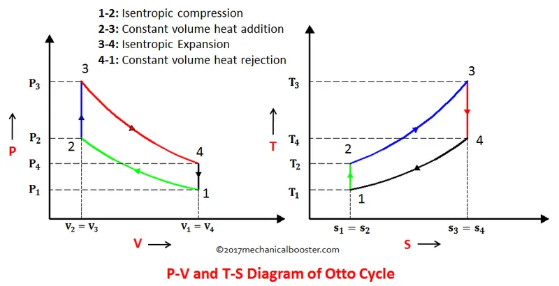
The otto cycle consists of four processes:
Process 1–2 compression stroke
Piston moves from crank end (BDC, bottom dead centre and maximum volume) to cylinder head end (TDC, top dead centre and minimum volume) as the working gas with initial state 1 is compressed isentropically to state point 2, through compression ratio (V1/V2). Mechanically this is the isentropic compression of the air/fuel mixture in the cylinder, also known as the compression stroke. This isentropic process assumes that no mechanical energy is lost due to friction and no heat is transferred to or from the gas, hence the process is reversible. The compression process requires that mechanical work be added to the working gas. Generally the compression ratio is around 9–10:1 (V1:V2) for a typical engine.
Process 2–3 ignition phase
The piston is momentarily at rest at TDC. During this instant, which is known as the ignition phase, the air/fuel mixture remains in a small volume at the top of the compression stroke. Heat is added to the working fluid by the combustion of the injected fuel, with the volume essentially being held constant. The pressure rises and the ratio (P3/P2){displaystyle (P_{3}/P_{2})} is called the "explosion ratio".
Process 3–4 expansion stroke
The increased high pressure exerts a force on the piston and pushes it towards the BDC. Expansion of working fluid takes place isentropically and work is done by the system on the piston. The volume ratio (V4/V3) {displaystyle V_{4}/V_{3}} is called the "isentropic expansion ratio". (For the Otto cycle is the same as the compression ratio (V1/V2{displaystyle V_{1}/V_{2}}). Mechanically this is the expansion of the hot gaseous mixture in the cylinder known as expansion (power) stroke.
Process 4–1 idealized heat rejection
The piston is momentarily at rest at BDC. The working gas pressure drops instantaneously from point 4 to point 1 during a constant volume process as heat is removed to an idealized external sink that is brought into contact with the cylinder head. In modern internal combustion engines, the heat-sink may be surrounding air (for low powered engines), or a circulating fluid, such as coolant. The gas has returned to state 1.
FORMULAS:
- Swept volume (v_swept) = (pi/4*d^2)/l
where, ‘d’ is the diameter of the piston & ‘l’ is the height of the piston. - Clearance volume (v_clearance) = v_swept/(cr-1)
- Total volume (vt) = v_swept+v_clearance
- Adiabatic process – pv^gamma = constant
Change of volume inside the chamber:
(v/v_c) = 1+0.5*(cr-1)*[R+1-cos(theta) –(R^2-sin(theta)^2)^0.5]
- Thermal efficiency of the otto cycle = 1-(1/cr^(gamma – 1))
OBJECTIVE: To write a program for otto cycle and plot a p-v graph and calculate the thermal efficiency of the cycle.
PROCEDURE:
FOR MAIN PROGRAM:
- As MATLAB is a case sensitive software, make sure of that during the programming. And clear and close all the previous data before starting.
close all (closes all the previous plots )
clear all (clears all the variable data )
clc (clears the command window)
- Now for starting the program the inputs are ‘gamma’ i.e the ratio of specific heats of the fluid is 1.4 and the temperature at point 3(t3) is 2300.
- Pressure and temperature at point 1 are 101325 and 500.
- Now enter the engine geometric parameters, bore = 0.1, stroke = 0.1, connecting rod length(con_rod) = 0.15, compression ratio (cr) = 12.
- Now for calculating the swept volume, (s_swept) = (pi/4)*bore^2*stroke and for clearance volume (v_clearance) = v_swept/(cr-1).
- Now volume at point 1 can be obtain by v1 = v_swept + v_clearance and the volume at point 2 will be v2 = v_clearance.
- Now calculate the volume & pressure for each points. For the variables at state point 2, pressure is calculated by adiabatic process equation p2v2^gamma = p1v1^gamma on simplifying p2= p1*cr^gamma and temperature is obtained by ideal gas equation t2= p2v2t1/p1v1.
- Now constant in adiabatic equation ‘constant_c’ is ‘p1v1^gamma’.
- Now compression volume (v_compression) is calculated by calling the function “energy_kinematics) and the compression pressure is calculated by constant_c/v_compesson^gamma.
- Now for state point 3 volume at point 3 is equal to volume at point 2 (v3=v2). Then pressure is calculated by ideal gas equation p3v3/t3= p2v2/t2 on simplifying p3= p2t3/t2.
- Now constant in adiabatic equation ‘constant_c’ is ‘p3v3^gamma’.
- Now expansion volume (v_expansion) is calculated by calling the function “energy_kinematics” and the expansion pressure is calculated by constant_c/v_expansion^gamma.
- Now variable at state point 4, volume at point 4 is equal to volume at point 1(v4=v1) and pressure(p4) = p3(v3/v4)^gamma.
Now for plotting the p-v diagram, use ‘hold on’ command to plot all points and lines in single figure and ‘hold off’ to close the command.
- Now for plotting the points and the curves btw them:
- For point 1 plot(v1, p1,’*’,’color’,’r’)
plot(v_compression,p_compression) - For point 2 plot(v2,p2,’*’,’color’,’m’)
plot([v2 v3],[p2 p3])
- For point 3 plot(v2,p2,’*’,’color’,’g’)
plot(v_expansion,p_expansion)
- For point 4 plot(v2,p2,’*’,’color’,’k’)
plot([v4 v1],[p4 p1])
- Run or complile the program with ‘F5’.
close all
clear all
clc

%To write the program for otto cycle & p-v graph an thermal efficiency

%state variable inputs
p1 = 101325; %pressure at point 1 in pascal
t1 = 500; %temperature at point 1 in kelvin
gamma = 1.4; %ratio of specific heat of the fluids
t3 = 2300; %temperature at point 3 in kelvin

%engine geometric parameters
bore = 0.1; %diameter of bore in meters
stroke = 0.1; %height of the cylcinder in meters
con_rod = 0.15; %length of teh connecting rod
cr = 12; %commpression ratio

%calculating the swept volume and clearance volume
v_swept = (pi/4)*bore^2*stroke;
v_clearance = v_swept/(cr-1);
v1 = v_swept+v_clearance; %volume at point 1
v2 = v_clearance; %volume at point 2

%state variable at point 2
%adiabatic process equation
%p1v1^gamma = p2v2^gamma
p2 = p1*cr^gamma;
%ideal gas equation
%p1v1/t1 = p2v2/t2
t2 = p2*v2*t1/(p1*v1);

constant_c = p1*v1^gamma; %constant
v_compression = engine_kinematics(bore,stroke,con_rod,cr,180,0); %calling the function for the compression volume
p_compression = constant_c./v_compression.^gamma; %compression pressure

%state variable at point 3
v3 = v2; %volume at point 3 is equal to volume at point 2
%ideal gas equation
%p3v3/t3 = p2v2/t2
p3 = p2*t3/t2;

constant_c = p3*v3^gamma;
v_expansion = engine_kinematics(bore,stroke,con_rod,cr,0,180); %calling the function for the expansion volume
p_expansion = constant_c./v_expansion.^gamma; %expansion pressure

%state variable at point 4
v4 = v1;
p4 = p3*(v3/v4)^gamma; %adiabatic process equation


%thermal efficiency
thermal_efficiency = 1-(1/cr^(gamma-1));

%plotting

hold on

plot(v1,p1,'*','color','r');
plot(v_compression,p_compression);
plot(v2,p2,'*','color','m');
plot([v2 v3],[p2 p3]);
plot(v3,p3,'*','color','g');
plot(v_expansion,p_expansion);
plot(v4,p4,'*','color','k');
plot([v4  v1],[p4 p1]);
title('otto cycle');
legend('1','1-2 isentropic compression','2','2-3 cont. vol. heat addition','3','3-4 isentropic compression','4','4-1 cont. vol. heat addition');
ylabel('pressure');
xlabel('volume');

hold off
FUNCTION PROGRAM:
- For any function program never use ‘close all’ , ‘clear all’ & ‘clc’ command.
- For function program the name of the function and the name of the file should be same.
- Now start the function as :
function[v] = engine_kinematics(bore,stroke,con_rod,start_crank,end_crank)
- Now the input parameters for the function are
- Crank pin radius (a) = stroke/2
- The ratio (R) = con_rod/a
- Now swept volume (v_s) = pi/4*bore^2*stroke. And clearance volume (v_c) = v_s/(cr-1).
- Now for the angle made by the crank is theta and it is given by theta = linspace(start_crank,end_crank,100). Here, linspace is used for thaking 100 values btw start and end crank point with the equal interval.
- Now, the volume in the cylinder is
(v/v_c) = 1+0.5*(cr-1)*[R+1-cos(theta) –(R^2-sin(theta)^2)^0.5]
- The above equation is divided into 3 terms for simplification:
- term1 = 0.5*(cr-1)
- term2 = R+1-cos(theta)
- term3 = (R^2-sin(theta)^2)^0.5
- Now calculate the volume (v) = (1+term1*(term2-term3))*v_c
- Now end the function with ‘end’ and save the function with the same name. Use the function by calling the function with the name of the function in any program. Make sure to enter the values in same order in which you have assigned the function.
function[v] = engine_kinematics(bore,stroke,con_rod,cr,start_crank,end_crank)

a = stroke/2;
R = con_rod/a;
v_s = (pi/4)*bore^2*stroke;
v_c = v_s/(cr-1);
theta = linspace(start_crank,end_crank,100);

term1 = 0.5*(cr-1);
term2 = R+1-cosd(theta);
term3 = (R^2-sind(theta).^2).^0.5;

v = (1+term1*(term2-term3)).*v_c;
end
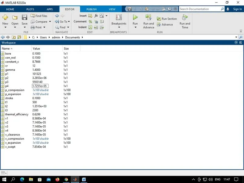
WORKSPACE:
PLOT: The p-v graph is shown below:
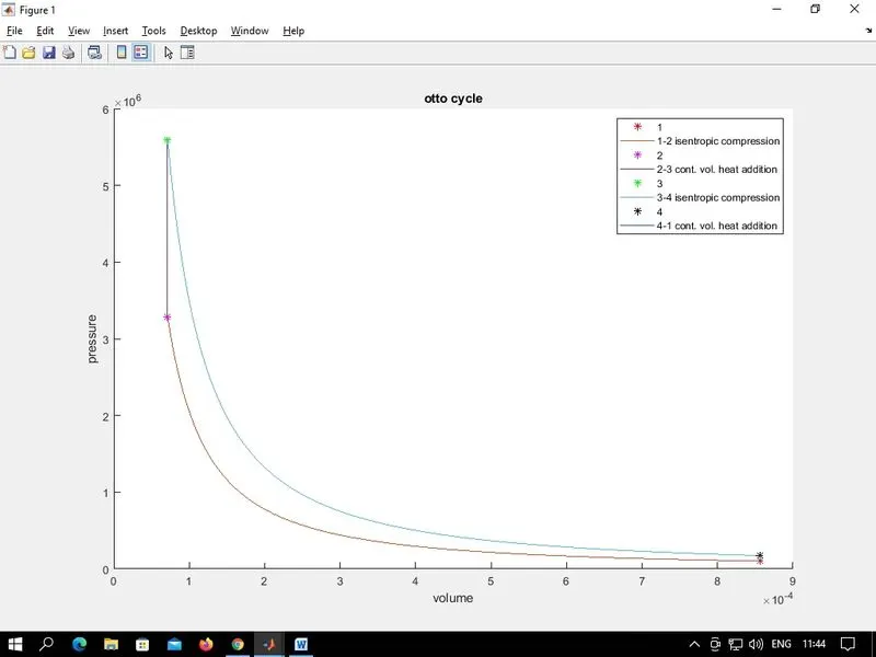
CONCLUSION:
The p-v graph of the otto cycle is formed. And the efficiency of the otto cycle is 0.6299 which is 62.99%.