Week 2 Challenge : Surface meshing on a Pressure valve
OBJECTIVE: To perform surface meshing on a pressure valve.
PROCEDURE:
We start by importing the geometry file in ANSA software, after which the very first step is to perform a geometry check with selected criteria as per the meshing requirement so that if there is any error in the geometry imported we can be aware of that and use the tools from TOPO deck to perform a topology cleanup.
When we perfromed the geometry check we majorly found single CONS error and cracks between cons.
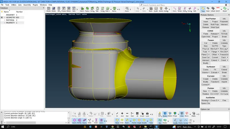
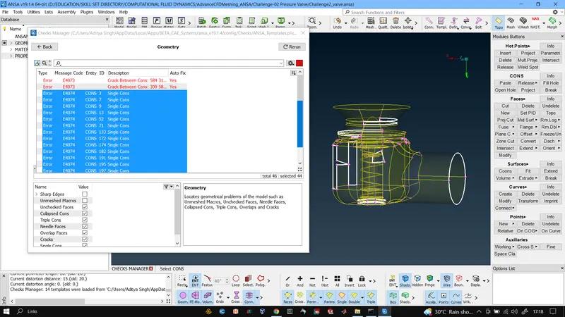
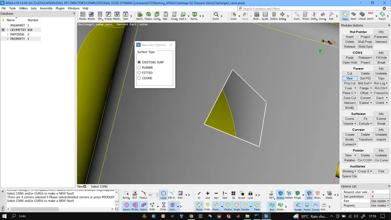
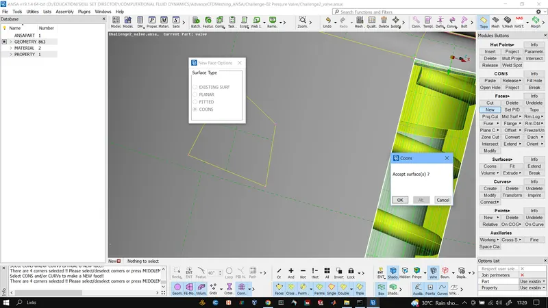
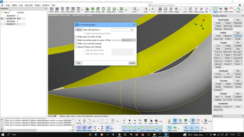
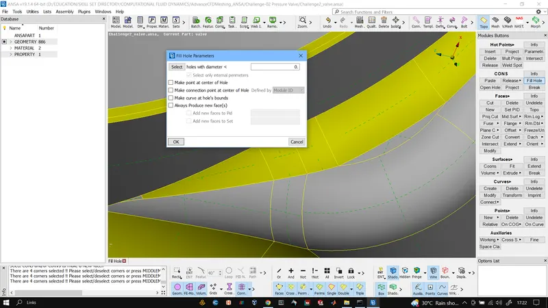
After finding the location of erros by selecting them from the list we use the "new" tool from face section and "fill hole" tool from the cons section. The new tool offers 4 different algorithms which can be used to form new surfaces here we majorly used COONS and EXISTING SURFACE algo to create new face and also used the fill hole tool for cracks and small holes. Using these tools all the erros were removed and also as it would used for CFD simulation purpose the control volume was created by closing the geometry which caused tripple CONS which was ignored as we knew why it was there.
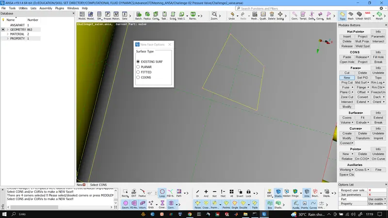
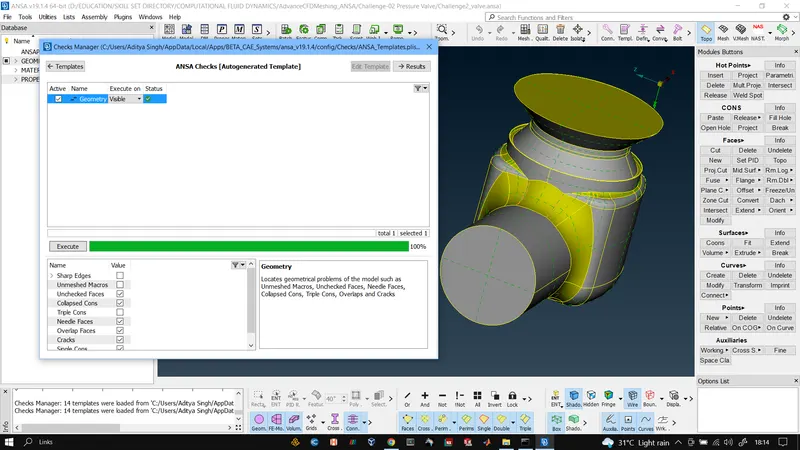
Affter performing all the cleanups once again a geometry check was performed so as to check if there is no error which got left behind or ignored.
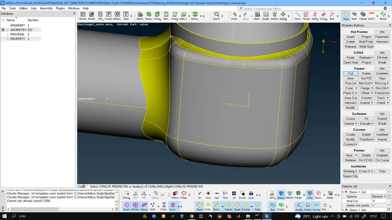
After this we used the "cut" tool from face section to remove all the small surface and merge them with appropriate larger surfaces as these small surfaces would cause trouble in meshing as they could lead to target length errors when going with large target length.
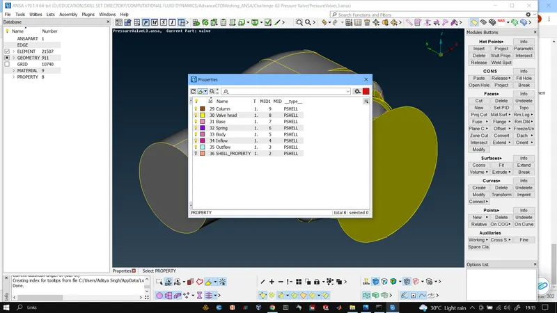
After this PIDs were created they are like name selection or boundaries but with more settings and features. We created in total 7 PIDs by appropriate names and parts were assigned to the PIDs accordingly.
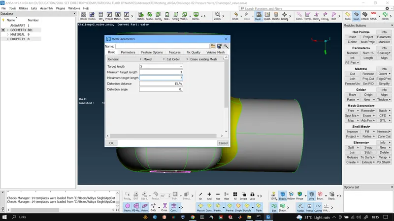
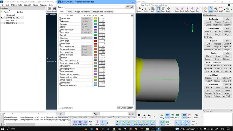
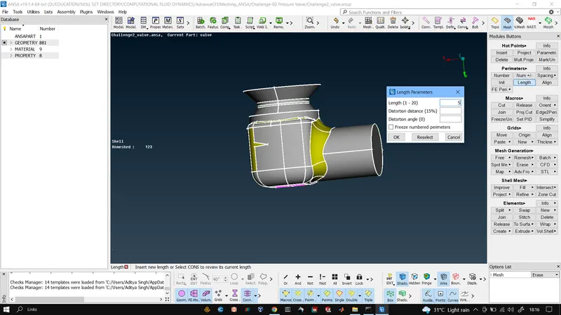
Once the PIDs were created and parts were assigned to them we move to surface meshing deck, where the very first task we do is give minimum and maximum length parameters in Quality and then give target length with min and max length in Mesh settings also element type is set as tria, after that we use the length tool inn perimeters and give macros and perimeter the target length and then use the CFD Meshing tool in mesh generation to generate meshes.
RESULTS:
TARGET LENGTH 5MM

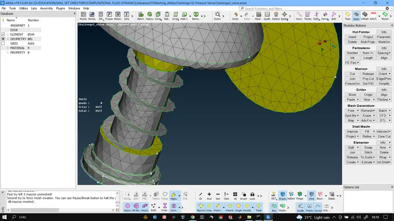
TARGET LENGTH 3MM
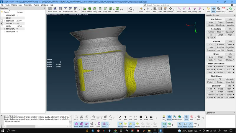
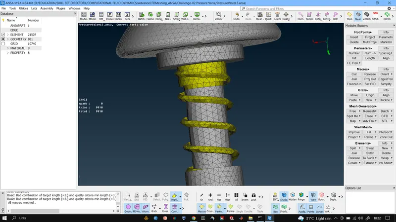
TARGET LENGTH 1MM
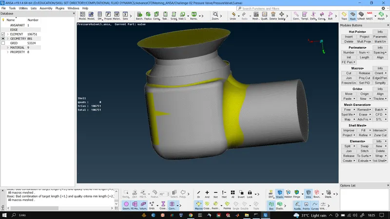
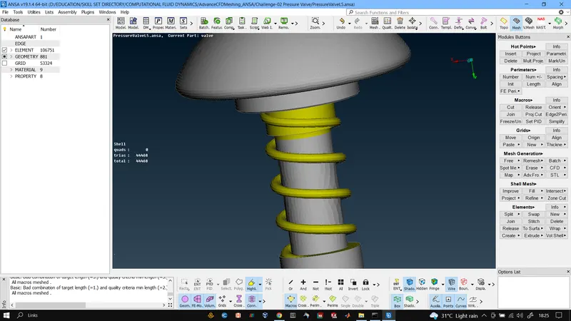
CONCLUSION: After successfully meshing for all 3 target lengths the major difference observed was that with larger target lengths of 3 and 5 mm we saw that geometric profile of parts were not captured perfectly and the most affected part was spring as for 5mm it only came out as a flat surface and for 3mm we saw that it had very sharp edges where as in reality it is a cylindrical tube. But with 1mm mesh we saw that the geometric profiles of all parts were captured smoothly. Also the number of cells changed with different target lengths.
So we can say to have accurate simulation results and perfect geometric profiles smaller target length is desired but it requires more computational power and time to generate.