Week 2 Challenge : Surface meshing on a Pressure valve
Aim: To perform topology clean up and mesh the geometry with three different mesh length elements.
Take away:
By the end of the discussion one will be able to,
- Get familier with different tools to clean the geometry.
- Use different size mehs elements and figure out which is better for capturing the physics.
===============================================================================
CASES:
- 1 mm
- 3 mm
- 5 mm
The procedure for cleaning the geometry for all the cases is same. The only difference is the mesh element size/length.
==============================================================================
Initial geometry:
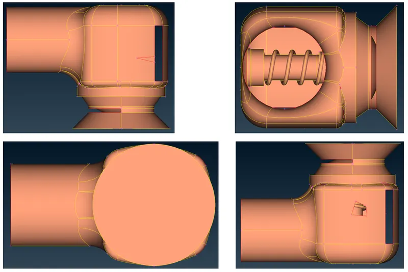
- As seen in the above geometry, there are lot of gaps and unwanted regions which must be taken care of.
- This is done in TOPO deck.
- Mesh deck is the later stage of the process.
==============================================================================
TOPOLOGY CLEAN UP:
- The very first step is to do a geometry check.
- Look out for single and triple CONS or intersecting region.
----> Exploring the FILL HOLE OPTION:
- Make sure you are in TOPO deck.
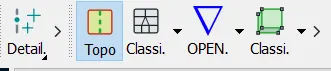
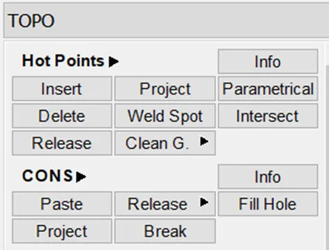
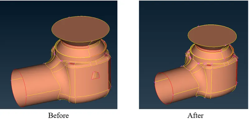
- Select FILL HOLE option. (TOPO --> CONS --> FILL HOLE)
----> Exploring the CUT option:
- Sometimes there could be edges which are unnecessary and might affect the quality of mesh.
- This can be avoided by using the CUT option.
- Selet CUT option. (TOPO --> FACES --> CUT)
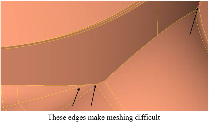
- Outcome of CUT option:
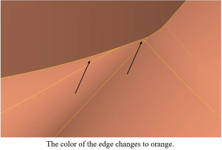
- Orange edge makes it redundant.
----> Exploring the FACES option:
- This option is used when there is a face missing. Look out for an example shown below.
- Select FACE option. (TOPO --> FACE --> NEW)
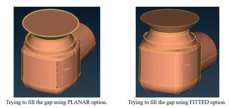
- You will be asked to select any of the four option.
- When any one of the option does not work, try using other option out of the four.
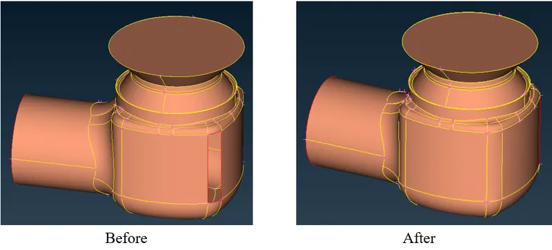
- Like wise any unfilled area can be filled with using this option.
----> Assigning the respective PIDs:
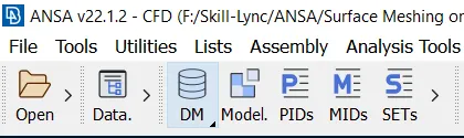
- Select PIDs option present at the top left corner of the viewport.
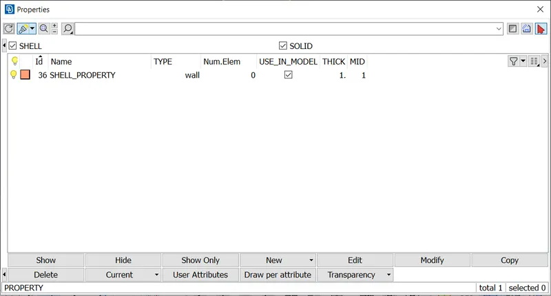
- A window will pop up.
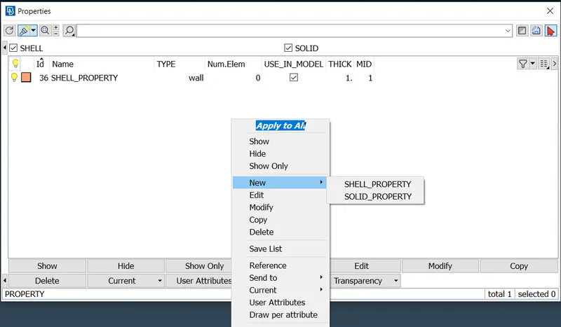
- Right clicking on the window will pop up. Selec New --> Shell Property
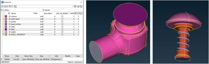
- After assigning the PIDs, all the component are coloured in different colour for better differentiation.
==============================================================================
MESHING THE GEOMETRY:
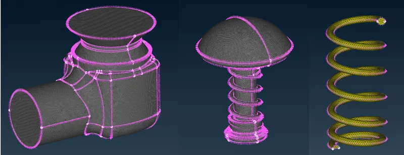
- There are three cases as defined above. (1mm, 3mm, 5mm).
CASE 1:
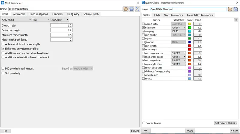
- Target Length = 1 mm
- Minimum Length = 0.5 mm
- Maximum Length = 2 mm
- These values must be specified in ANSA in MESH PARAMETERS AND QUALITY CRITERIA.
- Make sure element type is TRIA.
- Select SPOT MESH option under MESH GENERATION TAB.
- Select LENGTH option from PERIMETERS tab. (MESH --> PERIMETERS --> LENGTH)
- Select perimeters, drag all over the geometry to select the whole geometry and assign the value of mesh length as 1 mm. Similarly do it for macros.
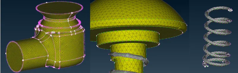
CASE 2:
- Target Length = 3 mm
- Minimum Length = 2 mm
- Maximum Length = 5 mm
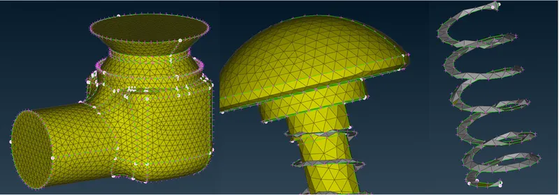
CASE 3:
- Target Length = 5 mm
- Minimum Length = 3 mm
- Maximum Length = 7 mm
Conclusion:
- Mesh length of 1 mm gives very fine results compared to other two cases.
- In cases 2 and 3, the mesh element size is greater than the smallest feature of the geometry. Hence it is unable to capture those areas approriately.
- If seen in the last case, the spring is pretty much flatend, which is not the desirable result.
- Similary in case 2, the valve head is not mesh properly. It has distortions near the circumference.
- Therefore, this concludes that, case 1 is the best mesh out of the three and must be used for furtur analysis.