Week 2 Challenge : Surface meshing on a Pressure valve
Aim –
To mesh pressure valve model in ANSA with 3 different target lengths and compare the final mesh result.
Procedure –
· Import the pressure valve model in ANSA and change the draw mode to PID. Next step is to check errors in the model using Check > Geometry tool.
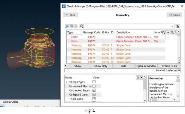
· Check tool shows that the model has many errors. Model needs to be cleaned up before meshing.
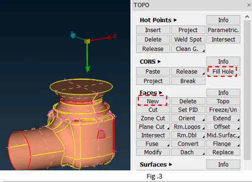
· Model majorly has single and cracks which needs to be rectified. Single cons in the model needs to be converted to double cons using various options like creating new surface or fill holes option in TOPO mode.
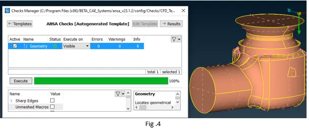
· Basically, the aim here is to create closed geometry for CFD analysis which can be done using options from the TOPO mode. Triple cons cannot be considered as error if those are created by the surface closing the geometry as shown below.
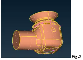
· After cleaning up the geometrical errors in the as shown, next step is to visually check the model for the lines/curves/cons that are very close to each other. If such curves are present in the model those could be removed using faces > cut option so that mesh generation process is smooth, as it is difficult to fit mesh elements in that region if the target length is greater than the distance between those curves.
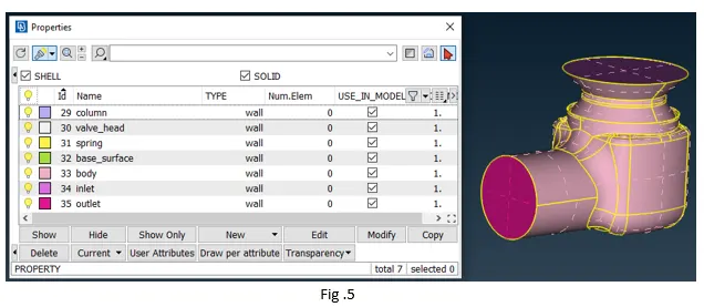
· Next step after geometrical cleanup is to split the cad into various PIDs as needed by the model using properties tools (ctrl+p).
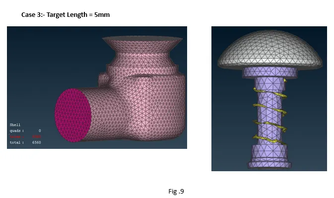
· Following step is to mesh the pressure valve model, using the mesh deck set the length for both perimeters and macro say 5mm. Set target length as 5mm in mesh parameters and min and max length in quality criteria as 3 and 7.
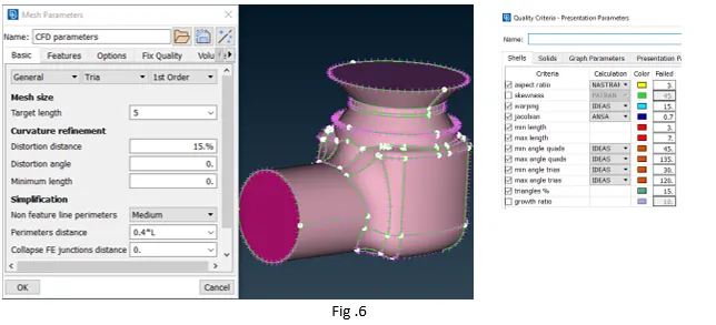
· After setting up all the parameters requred for meshing, generate the mesh using spot mesh algorithm under mesh generation.
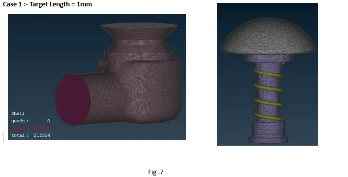
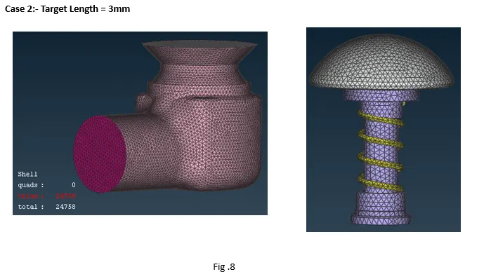
· Repeat the same process for generating mesh with length of target length of 1mm and 3mm.
Conclusion –
· Surface mesh was generated on pressure valve with 3 different target length, it is observed that with increase in target length mesh count has reduced significantly.
· On the other hand, small components like spring were not captured with target length of 3 and 5 mm.
· Similarly, the curvature on the valve head was not captured with the increase in target length.
· All the components were captured correctly with the target length of 1mm, but the mesh size was very high for the case, which can increase the computational time.
· From all the cases it can be inferred that the target length should be different for all the PIDSs depending on the size of components to be meshed.