Week 2 Challenge : Surface meshing on a Pressure valve
Title : Surface meshing of Pressure Valve using ANSA Meshing
Aim:- To create surface mesh of pressure valve using tria element and target mesh length of 5mm, 3mm, and 1mm.
Objectives: -
- Perform the geometry cleanup using different tools available in ANSA topo mode.
- Set three different target length, and mesh the model for three different cases.
- Analyze three cases and find out which is giving better results.
Introduction: -
ANSA (Analysis of Numerical Structural Analysis) is a powerful and versatile software tool used in the field of engineering and simulation. Developed by BETA CAE Systems, ANSA provides engineers, analysts, and researchers with a comprehensive suite of capabilities for pre-processing and post-processing tasks in the context of numerical simulations.
As the first step in any numerical analysis workflow, the pre-processing phase in ANSA allows users to construct and prepare complex models for simulation. ANSA offers an intuitive and user-friendly interface, making it easy to import CAD data, create geometries, mesh surfaces, and define material properties. It supports a wide range of industries, including automotive, aerospace, civil engineering, and more.
Moreover, ANSA excels in its meshing capabilities. It provides advanced meshing tools that enable the generation of high-quality finite element meshes, ensuring accurate and reliable simulations. Its automated meshing algorithms save time and effort, while manual meshing options allow for fine-tuning and optimization.
Step by Step Procedure
1) First of all we import the geometry model into ANSA.
2) We perform the geometry check to look for any single cons, double cons, cracks, overlap faces, needle faces etc.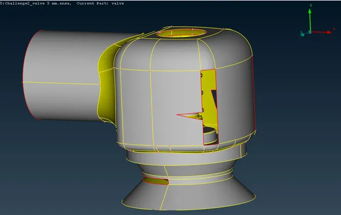
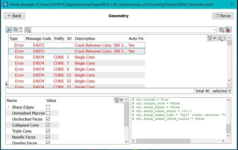
As we can see there are total 46 geometry error shown.
4) Perform the geometry cleanup and fix the errors using various tools available in Topo mode.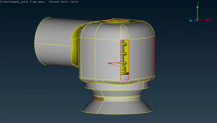
5) For creation of new face go to faces option à new à surface type. There are four different algorithms to create new surface, namely Existing Surf, Planar, Fitted, Coons.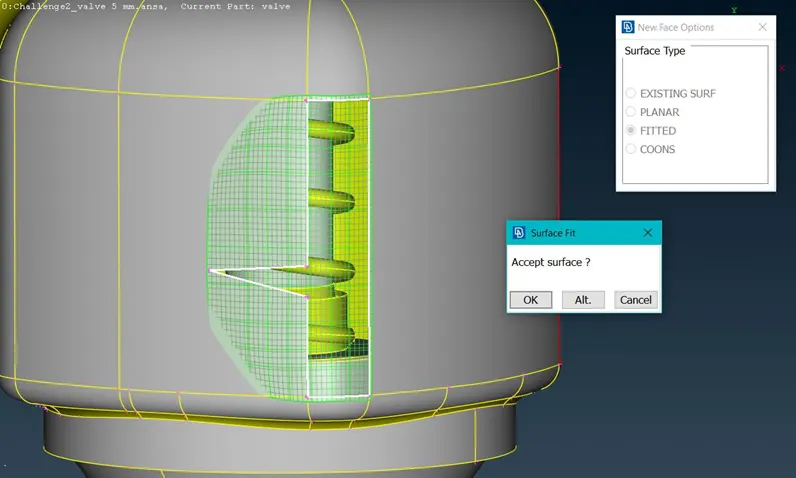
6) Similarly create surface for all the holes that are present in geometry.
7) After clearing all the geometry faults, check once again for any remaining faults.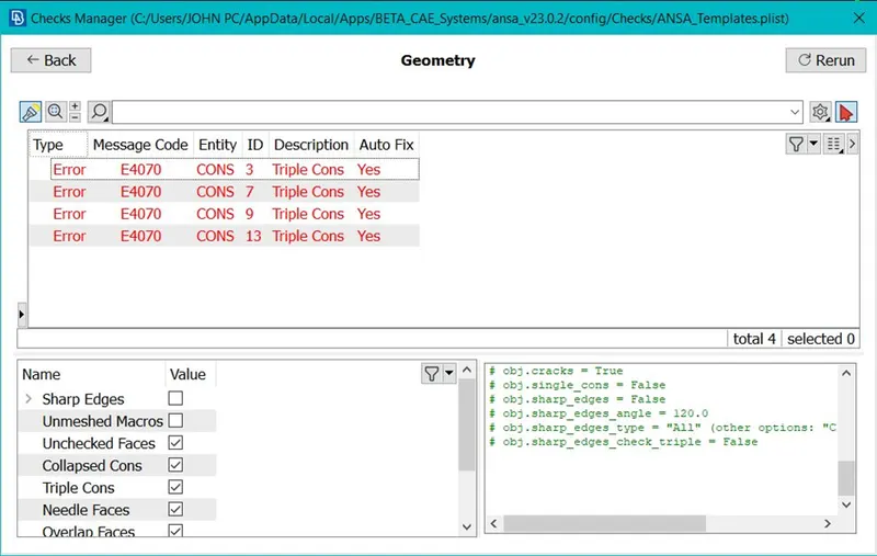
8) Using the cut option available under faces tab, remove the small cons which could be smaller than the mesh length.
9) In the properties ID manager create different PIDs to easily identify the parts of geometry and mesh them accordingly.
10) In properties tab go to new>Pshell>give name for the part and click ok
11)Different PIDs are created namely Inlet, Outlet, Body, Valve head, Spring, column, base.
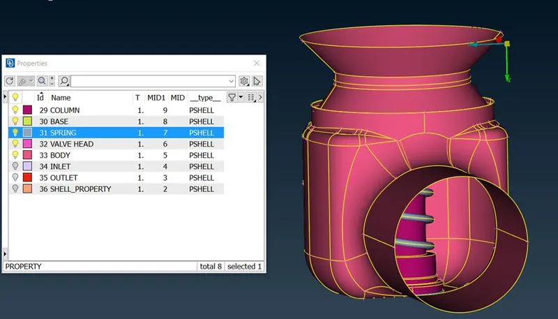
12) After naming all the parts we move on to mesh the geometry
Case 1:
Target Mesh length = 5 mm
Element type – Tria
Under perimeter tab, click on length and set the length to 5mm for both the perimeters and macros option.
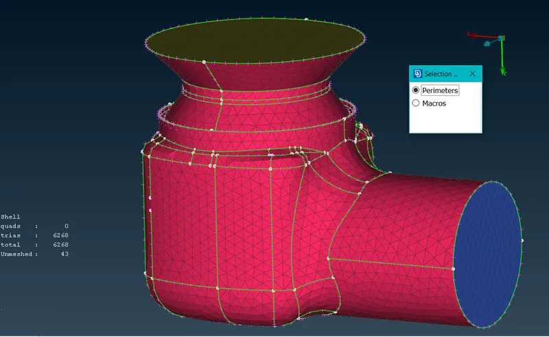
No. of Cells = 6268
Case : 2
Target mesh length = 3mm
Element type – Tria
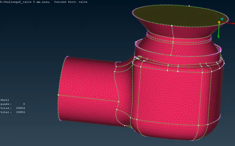
Total no. of Cells = 24806
Case 3:-
Target mesh length = 1mm
Element type – Tria
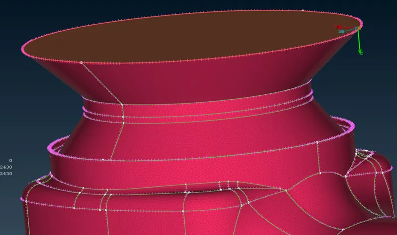
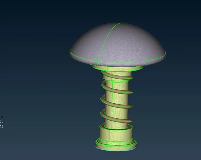
Total no. of Cells – 212430
Conclusions:-
- Surface mesh is created using ANSA 22.1 for three different cases by varying the mesh length from 1mm to 5mm.
- For mesh length 5mm, total no. of elements created is 6268. With this mesh size the geometry is not captured accurately. The spring and valve head curvature are smaller than mesh size hence the geometry gets distorted. This will give garbage results after CFD simulation.
- For mesh length 3mm, total no. of elements created is 24806. This mesh size also does not capture the geometry accurately.
- For mesh length 1mm, total no. of elements created is 212430. This mesh size capture the geometry well and all the curvatures takes perfect shape without any distortion.
- It can be concluded that same mesh length for all the PID surface is not suitable. Therefore we need to check the size of the PID surfaces and give the mesh size accordingly.
- Separate mesh size according to the PIDs size will give better and accurate results.