Week 2 Challenge : Surface meshing on a Pressure valve
AIM:
This project aims to mesh a pressure valve using three different mesh sizes and find out the optimal mesh size.
OBJECTIVES:
- Check for the geometrical errors and perform Topology cleanup.
- Set three different target lengths as three different cases and mesh the model. Target length = 1mm, 3 mm and 5 mm (i.e. 3 cases).
- Element type to be used is triangular.
- Apply any one target length from the above at a time for the entire model as One case thereby create 3 different models for 3 cases.
PROCEDURE:
The geometry of the pressure valve can be found here. It is a simple valve which consists an inlet, outlet and a spring that controls the outflow.
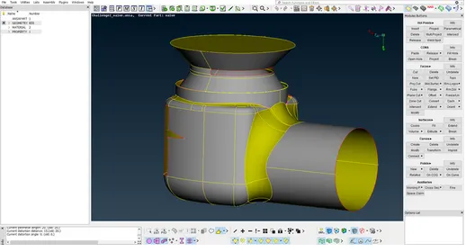
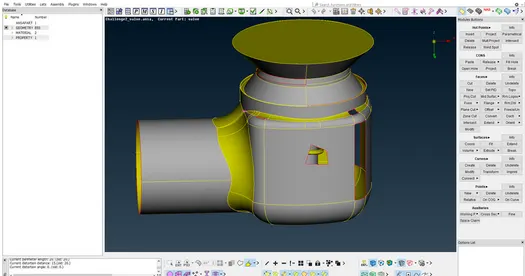
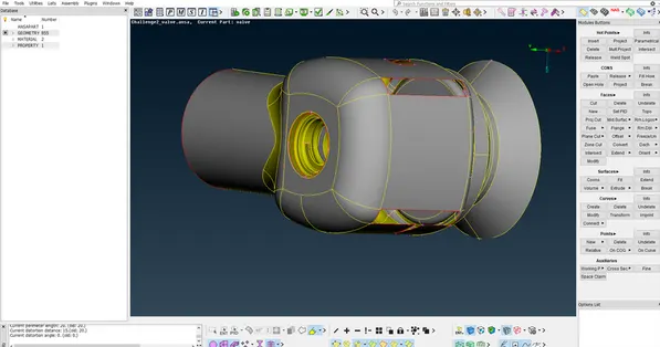
As we can see from the above pictures, the geometry has a lot of openings and holes. These features are not supposed to be in the geometry.
We also performed a topology check that shows as follows. For the topology check we enabled the single cons option. Which identifies entities such as lines that are shared only by one surface meaning openings.
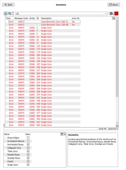
We solve these errors by filling all the openings on the geometry. For a CFD volumetric mesh these openings are not desirable hence we use the New option in the Faces tab. This will pop up a new menu as shown.
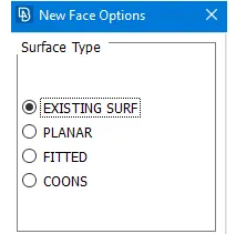
Existing surface option fills an opening on an existing surface. Coons options lets us select coons one by one and fills the opening. Fitted option does the same also provides alternatives on how the surface will be filled.
There is also another option called Fill-Hole in the Cons tab which as the name suggests fills the holes on surfaces. Using these option we fill all the openings and the resultant geometry is as shown.
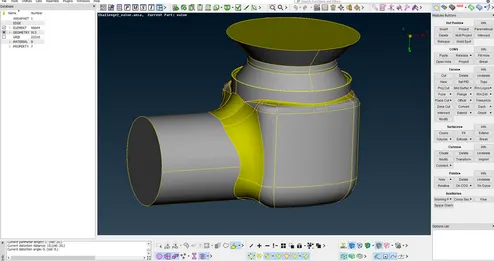
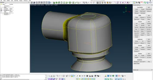
Once all the holes are filled we delete the lines that are on the same plane too close to each other or has smallest distance between them. Most of these lines are unnecessary. If these lines are present in the geometry, it will be a problem when the target length is greater than the distance between these lines. This error results in deformation of the geometry.
Once all these lines in the exterior are deleted we run a topology check and it will gives a green signal as shown in the fig below.
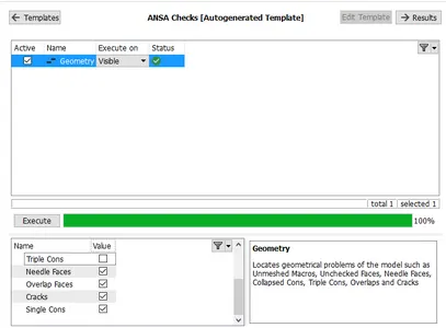
Notice that we have disabled triple cons option. If we had the triple cons option the following error would show up.
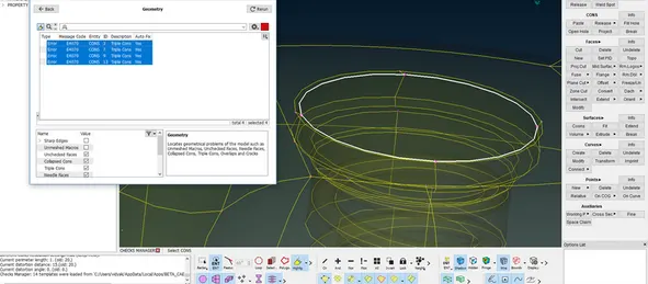
The 4 errors that are being shown there are the triple cons that we created when we sealed the valve head. This triple con is required as the geometry need to be water tight. Hence we disable to look for triple cons in the check and proceed with the next part which is PID ing the components.
Using the help of the property manager present in the top toolbar and the tools provided in the bottom toolbar we name the components as follows.
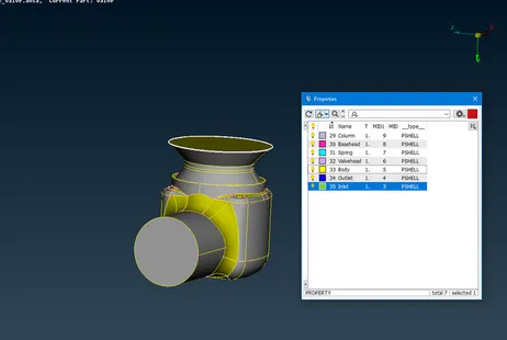
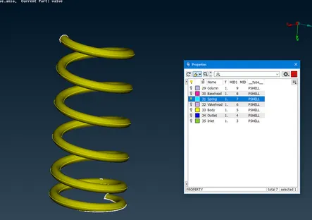
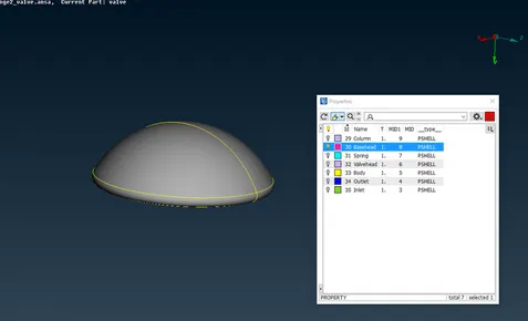
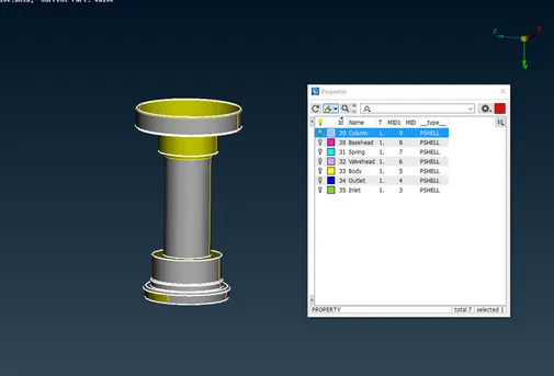
Now since everything is sorted we move onto meshing
Case 1 Target length = 5mm
1) To mesh select the meshing module, select the Length under Perimeters and give 5 mm as Perimeter and in Macros.
2) In the meshing parameter give Maximum target length as 7 mm and Minimum target length as 3 mm, for mesh type select Tria.
3) In the quality criteria give Maximum target length as 7 mm and Minimum target length as 3 mm.
We can use the PIDRegion option and select the components one by one to mesh the geometry. The internal components can be selected by hiding the exterior components either by using the not command or by using the property manager tool.
Results
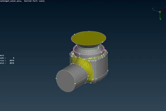
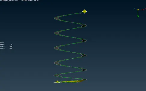
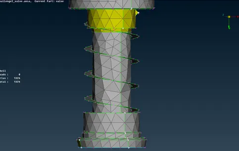
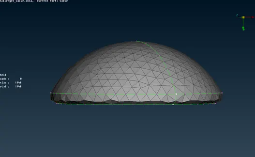
The total number of elements generated are 8168 and no unmeshed or quad cells. The external surface of the pressure valve is captured well with minor defeaturing at some curves but the internal components such as spring and the basehead was defeatured because the minimum target length was larger than that of coil diameter and the fillet radius of the valve head. The column is also defeatured because of the target length.
Case 2 Target length = 3 mm
1) To mesh select the meshing module, select the Length under Perimeters and give 3 mm as Perimeter and in Macros.
2) In the meshing parameter give Maximum target length as 5 mm and Minimum target length as 1 mm, for mesh type select Tria.
3) In the quality criteria give Maximum target length as 5 mm and Minimum target length as 1 mm.
Upon meshing we get the following results
Results
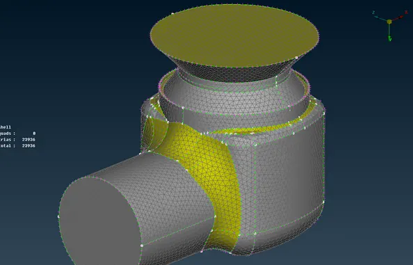
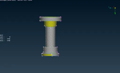
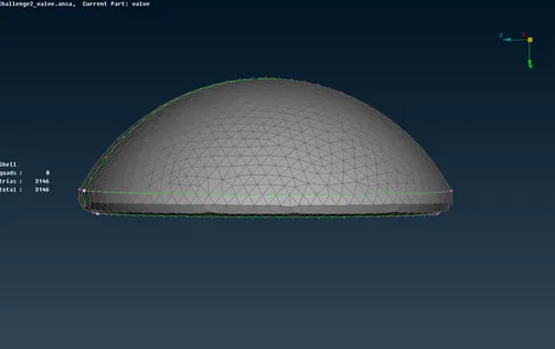
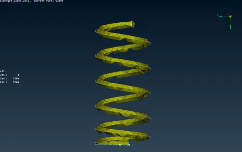
The total number of elements generated are 23936 and no unmeshed or quad cells. The external surface of the pressure valve is well captured but the internal components such as spring and the base head was defeatured because the minimum target length was larger than that of coil diameter and the fillet radius of the valve head. The column is captured correctly with less defeaturing.
Case 3 Target length = 1 mm
1) To mesh select the meshing module, select the Length under Perimeters and give 1 mm as Perimeter and in Macros.
2) In the meshing parameter give Maximum target length as 2 mm and Minimum target length as 0.5 mm, for mesh type select Tria.
3) In the quality criteria give Maximum target length as 2 mm and Minimum target length as 0.5 mm.
Upon meshing we get the following results.
Results
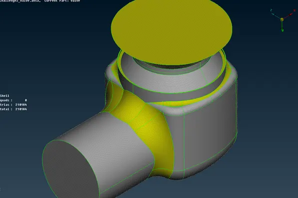
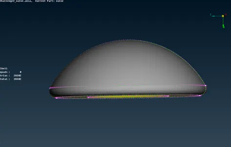
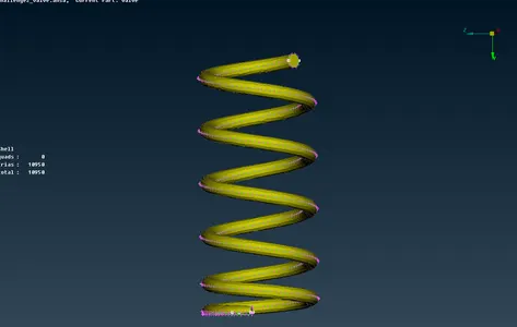
The total number of elements generated are 210184 and no unmeshed or quad cells. The external surface and the internal components of the pressure valve is captured well when compared to the other two cases.
CONSLUSION:
- From the above 3 cases it is concluded that the case 3 with 1 mm target length has little to no defeaturing and has retained the geometry of all components.
- Hence case 3 is giving the best results. But the catch is that it increases the computational time.
- To decrease the computational time the number of elements need to be decreased without having defeaturing. To achieve this the components need to be meshed individually with different target lengths.
- From the above 3 cases for the inlet, outlet and the valve head a target length of 5mm gives good results. While for the body and the column a target length of 3mm gives good results. For the base head and the spring a target length of 1mm gives good result.