Week 2 Challenge : Surface meshing on a Pressure valve
Aim: A Surface Meshing on a Pressure Valve using ANSA.
Objective:
- TO check the geometrical errors
- To perform topology clean-up accordingly
- Three different target lengths and three different cases and mesh the model.
Given Data
- Target length = 1mm, 3mm and 5mm
- Element type = Tria
Geometry of Model
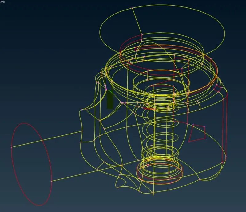
- Wireframe Given Model
- Shaded Model of Pressure Valve
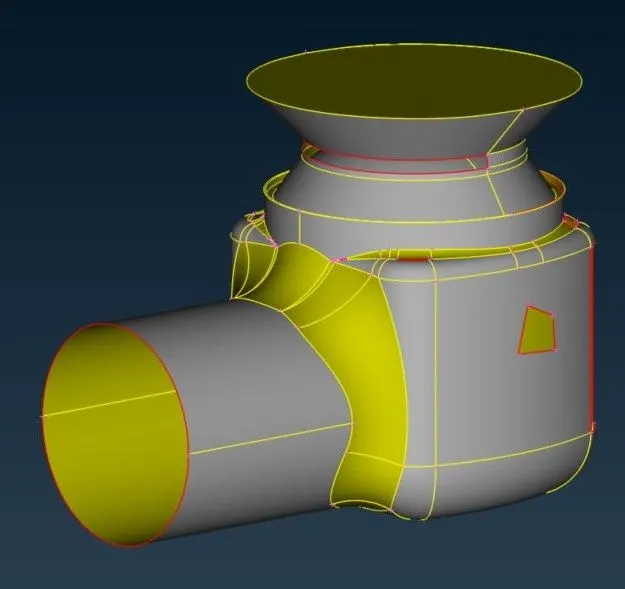
- A topological error is red in color as shown in the model.
- In this image we can see a lot of errors after geometry check up. As single cons will be present when there are open surfaces or cons that share edge with only one surface
- In 3D geometry for CFD applications we need closed surfaces to do volumetric mesh and we need to fix single cons.
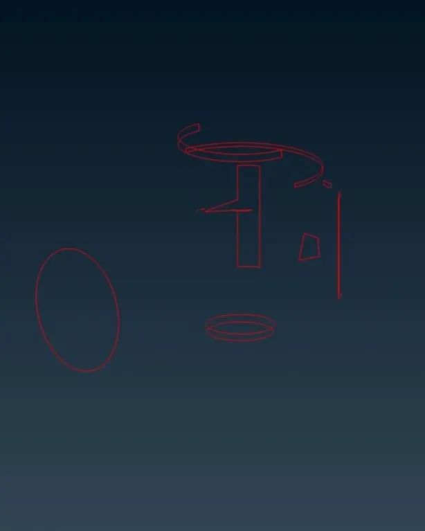
- Geometry Check-up
- The multiple errors are shown in the model. The warning is shown for a single cone which is not connected with the model.
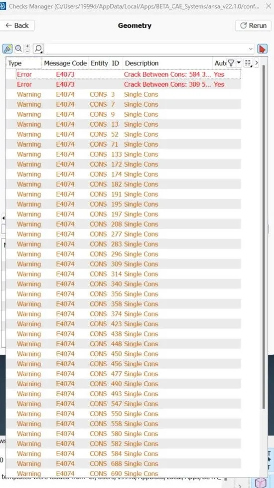
- The multiple errors are shown in the model. The warning is shown for a single cone which is not connected with the model.
- Resolving the error of single cons.
- The red marks are the errors which are not connected with the body.
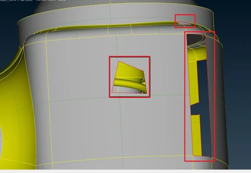
- The red marks are the errors which are not connected with the body.
- This is how it is patch up
- All geometry checks are corrected and again there are no red lines in the model.
- In this image we can observe that there are no single cons errors , but you have only triple cons at the bottom of the geometry as we have closed the bottom with a surface.
- Actually triple con is not an error, it's just a warning. We should always go to locations where there are triple cons and see whether triple cons are necessary or not. If not, try to remove them.
- Here in our case all the three surfaces are important, so there will be formation of triple con and we will ignore this triple con as all surfaces are important.
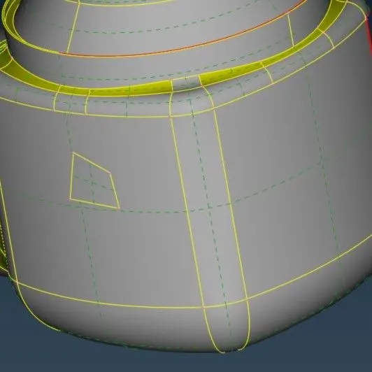
- All geometry checks are corrected and again there are no red lines in the model.
- Setting up the modele for PID's
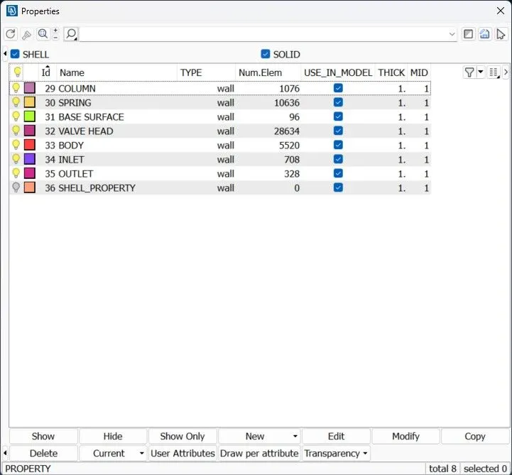
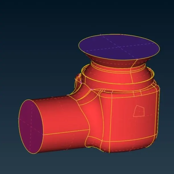
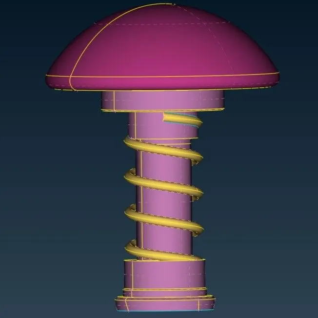
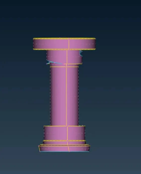
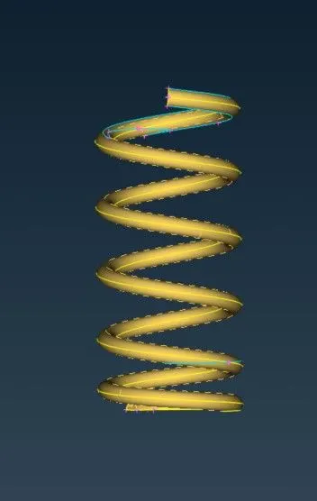
- The model as assigning PID's.
- The images of the model are after assigine of PID's.
- Inside Valve
- Column
- Spring
- The images of the model are after assigine of PID's.
Meshing Of Model
All the geometry is corrected and PID's are also applied to all the components and now our model is ready for meshing.
- We selected the meshing algorithm, and selected a Spot mesh for 1mm of length.
- Trias= 211554
- Total= 211554
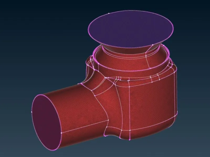
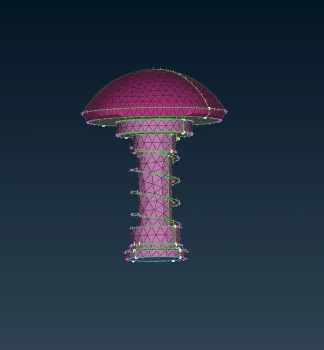
- Valve
- Trias= 60902
- Total= 60902
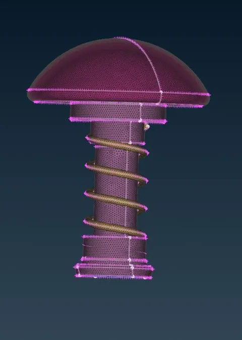
- We selected the meshing algorithm, and selected a Spot mesh for 3mm of length.
- Trias= 24656
- Total= 24656
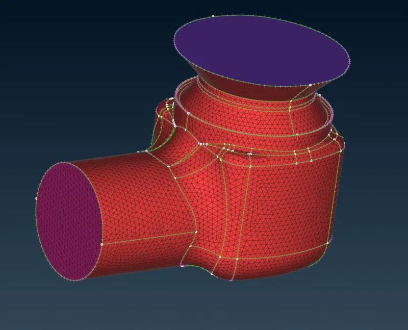
- Valve
- Trias= 7078
- Total= 7078
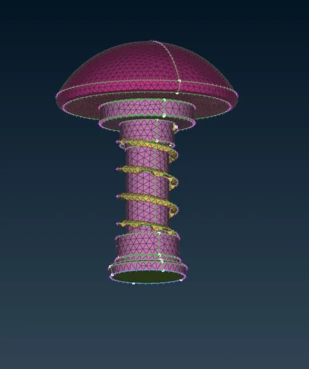
- We selected the meshing algorithm, and selected a Spot mesh for 5mm of length.
- Trias= 9150
- Total= 9150
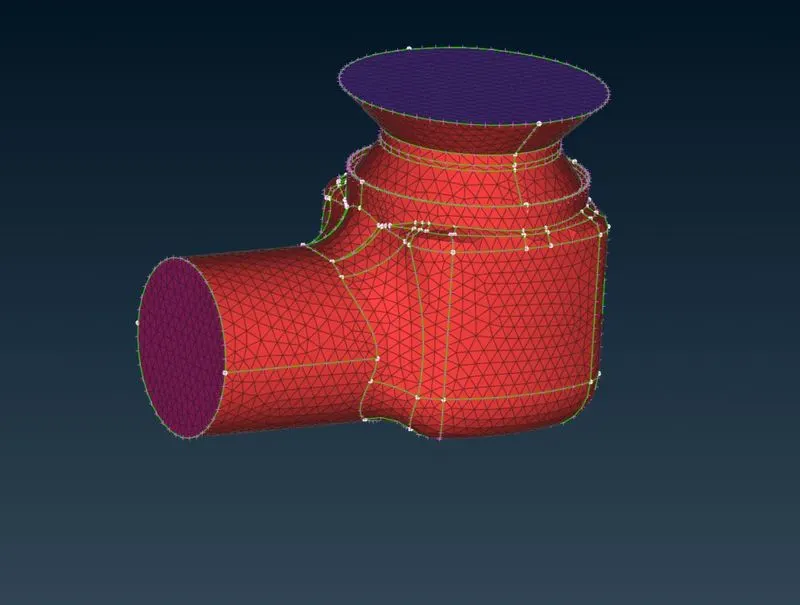
- Valve
- Trias= 2594
- Total= 2594
Conclusion:
- We have successfully meshed the given surface of the model with three different lengths i.e., 1mm, 3 mm, 5mm.
- It is concluded that the case 3, with 1 mm target length has little defeaturing and has retained the geometry of all components.
- Here we also found that smaller elements capture curvature of geometry more accurately.
- To decrease the computational time the number of elements we need to decrease without defeaturing. To achieve the components complet size is less or equal to the mesh size needs to be meshed individually with different mesh size.
- For the smaller parts like spring and column head the mesh length can be 1mm so the accuracy for smaller parts can be increased.