Week 2 Challenge : Surface meshing on a Pressure valve
Aim:
To mesh a pressure valve using three different mesh sizes & find out the optimal mesh size.
OBJECTIVES:
- Check for the geometrical errors & perform Topology cleanup.
- Set three different target lengths as three different cases & mesh the model. Target length = 1mm, 3 mm & 5 mm (i.e. 3 cases) & element type should be triangular.
Types of modules in ANSA :
- TOPO - Set of tools for Geometry clean-up & for setting up of PIDs.
- MESH - Tools to generate Surface Mesh or 2D Mesh.
- VOLUME MESH - To generate solid or 3D Mesh.
- SOLVER DECKS - Tools based on different solvers such as ABAQUS, RADIOSS ,ANSYS etc.
- MORPH - Advanced tool to capture geometry more accurately while meshing.
Solution procedure :
- Import the CAD model.
- Geometry check-up.
- Topo/Geometry cleanup.
- Setting-up of relevant PIDs.
- Defining the element size or length.
- Selection of Meshing type.
- Generating Mesh.
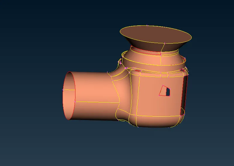
Importing of CAD model :
Go to file -> open -> browse the location of the CAD model -> select it click on open.
Geometry check-up :
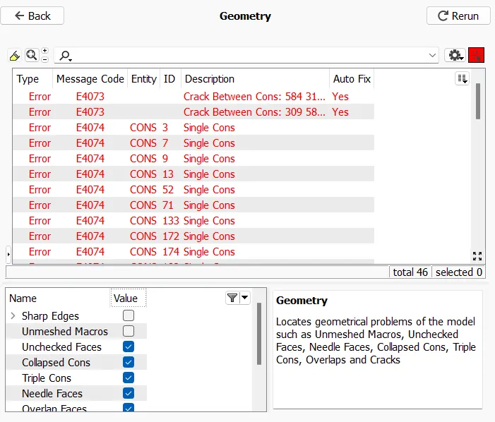
Geometry check-up is done to check whether there are any errors in the model.
To do this operation , go to toolbar -> checks -> geometry -> visible -> execute
Topo/Geometry cleanup :
- We will use visibility tools to see the single cons & we have to clear the single cons whereever they present .
- We will patch all the single cons by creating a new face over there .
- We will create / patch the surface by using the new under faces .
- Here we have 4 options to use under new , they are existing surface ,planar, coons & fitted.We will also use fill holes under cons.
- We use these different type of algorithms to create face depending upon the applications . So when one fails to create a better surface , we try with other alternate / algorithm.
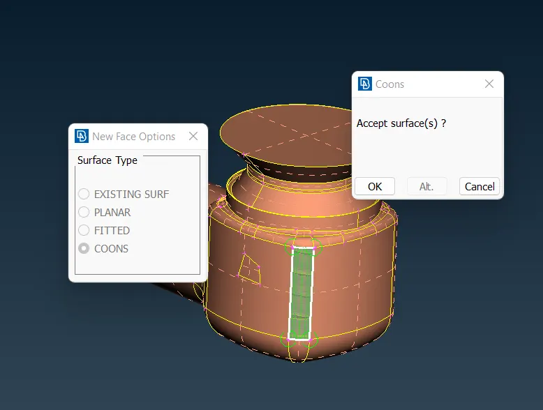
In the similar way we create surfaces wherever there are single cons by using the above algorithms.
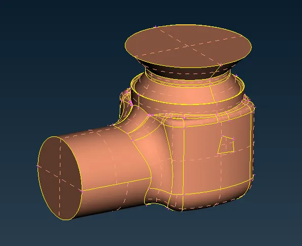
After all the patching let us do the geometry check again, to see whether any error exists or not.
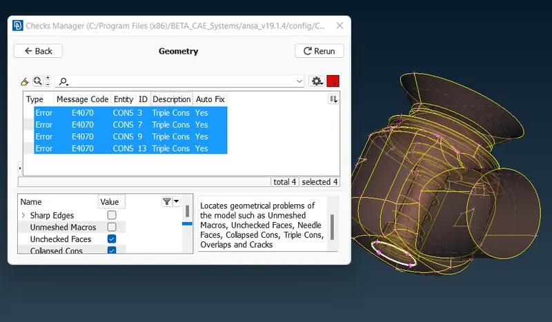
In the above image you can observe that there are no single cons errors, but you have only triple cons exists at the bottom of the geometry as we have closed the bottom with a surface. Actually triple con is not a error it's just a warning .We should always go to location where there are triple cons & see whether triple cons are necessary or not. If not try to remove them. Here in our case as all the three surfaces are important, so there will be formation of triple con & we will ignore this triple con as all surfaces are important.
Setting-up of Relevant PIDs :
- This is done to specify names to different boundary conditions for various parts.We need to activate cross hatches before setting-up PIDs.
- If you open properties manager at the top, you will have only one default PID.In order to create new PID, right click on properties manager-> click new -> then select pshell -> then again select pshell -> then give name in the popup box -> then ok .You can change the colour by double clicking on the colour box -> then ok .
- In the similar way create PID for inlet, outlet ,spring , valvehead, body, column , base surface.
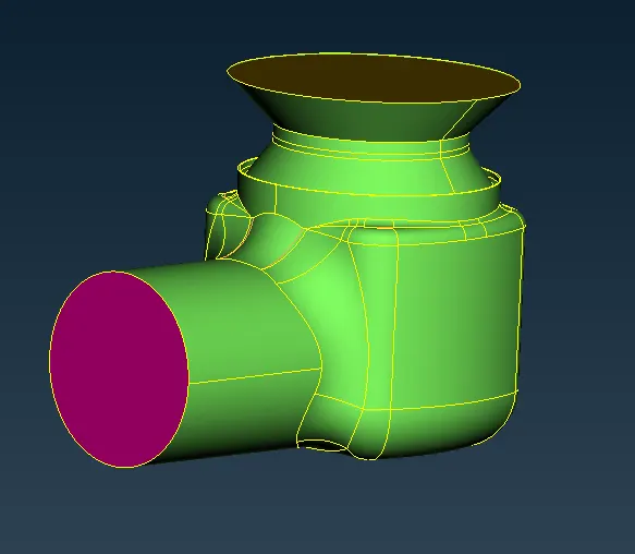
- Next, assign the PIDs to the geometry.
- Click apply & select the part.
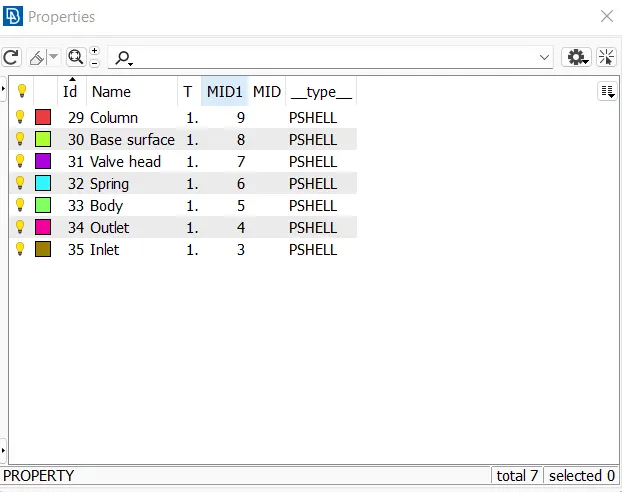
In the below image you can see the image of model after assigning PID's .
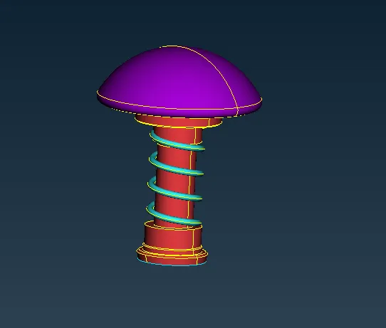
In the below image you can see the image of interior parts of the model after assigning PID's .
Defining the element size/length :
- Here we have three different target lengths as three different cases & we have to mesh the model with all three different lengths.
- Target length = 1mm, 3 mm & 5 mm (i.e. 3 cases).
- Let's first mesh with three different sizes & then finally conclude by comparing the results of all the three cases.
Case -1 :- Target length = 1 mm :
- 1) under perimeters we give length as 1mm 2) under macros we give length as 1mm.
Go to mesh utility -> perimeters -> length -> now select perimeters & then-> click left mouse button & drag & select the entire model -> click middle mouse button -> Enter the element length as 1 mm -> Click middle mouse button.
In the similar way select macros instead of perimeters under length & give mesh length as 1 mm.
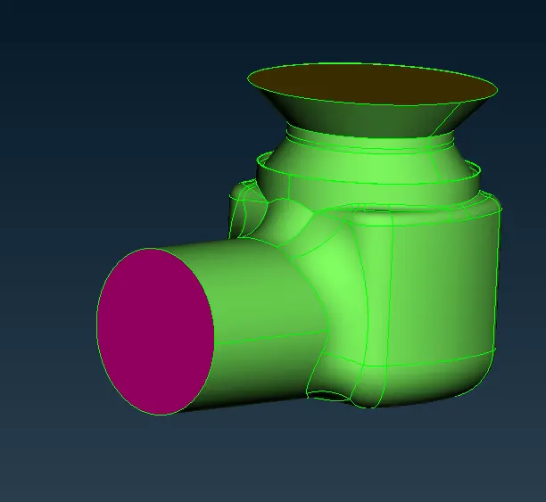
You can see the inside parts of the model after giving the mesh length in the below image.
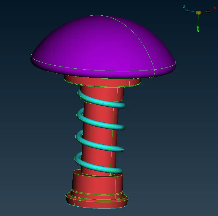
3) Under mesh parameters we have to give at the target length as 1 mm & select element as tria & aslo give min & max length as 0.5 mm & 2 mm respectively & keep remaining to default. 4) In quality criteria we have to give min & max length as 0.5 mm & 2 mm respectively.
Selection of meshing type & generating mesh :
Go to Mesh Generation -> spot Mesh -> tria -> drag & select the entire model -> click on the scroll button/ middle mouse button on mouse to mesh (or) we can directly select visible under drop down menu of spot mesh instead of drag & select the entire model .
The model after generation of mesh is shown in below image.
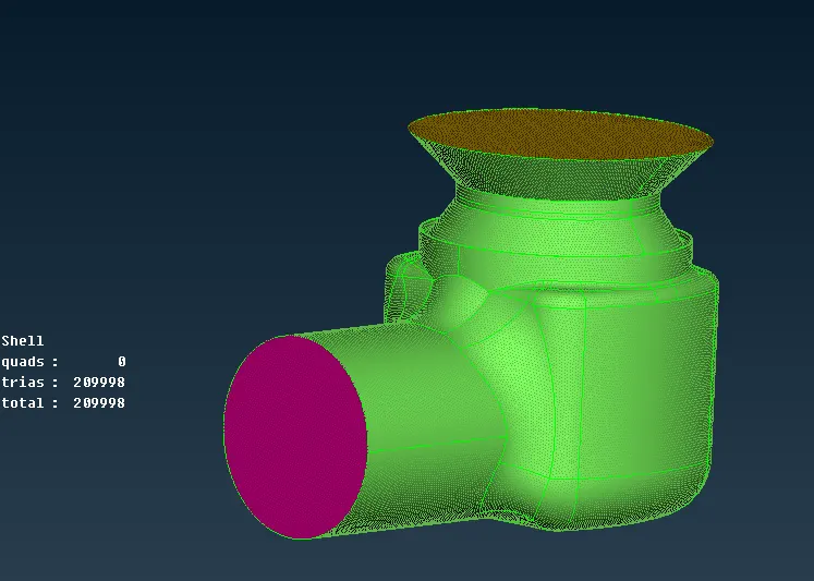
The below image is the final view of inside parts of the model after generation of mesh .
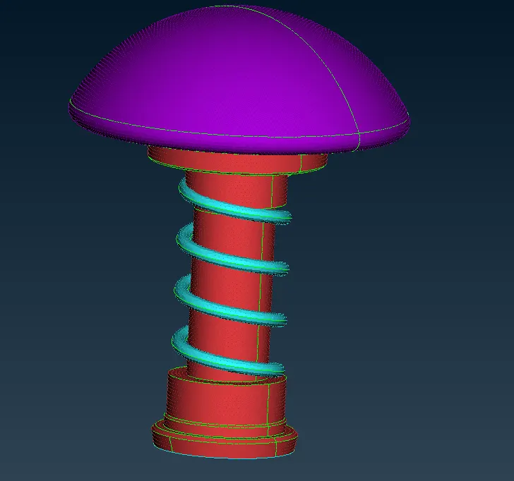
Case -2 :- Target length = 3 mm :
- Everything is same as above case but the only change here is ,the target length changes to 3mm.
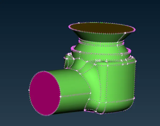
For meshing also we follow the same process as in the previous case. The model after generation of mesh is shown in below image.
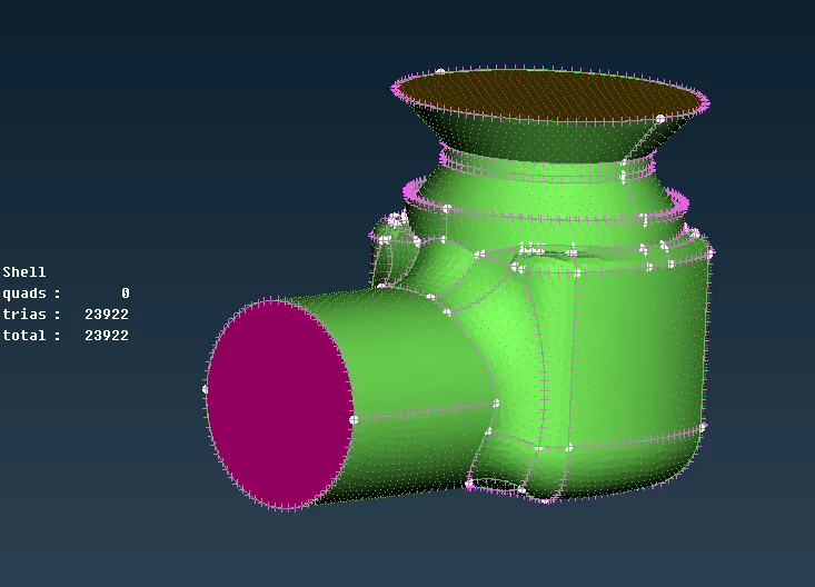
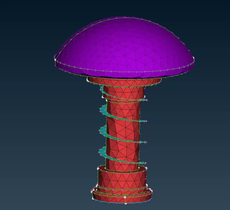
The below image is the final view of inside parts of the model after generation of mesh .
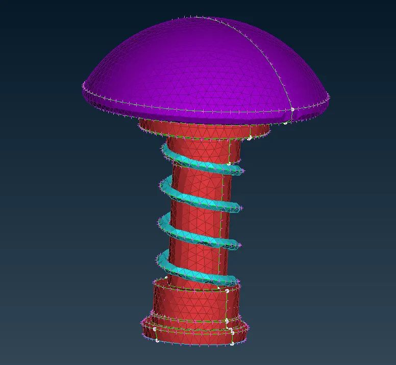
Case -3 :- Target length = 5 mm :
- Everything is same but the only change here is ,the target length changes to 5 mm .
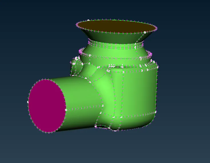
For meshing also we follow the same process as in the previous case.
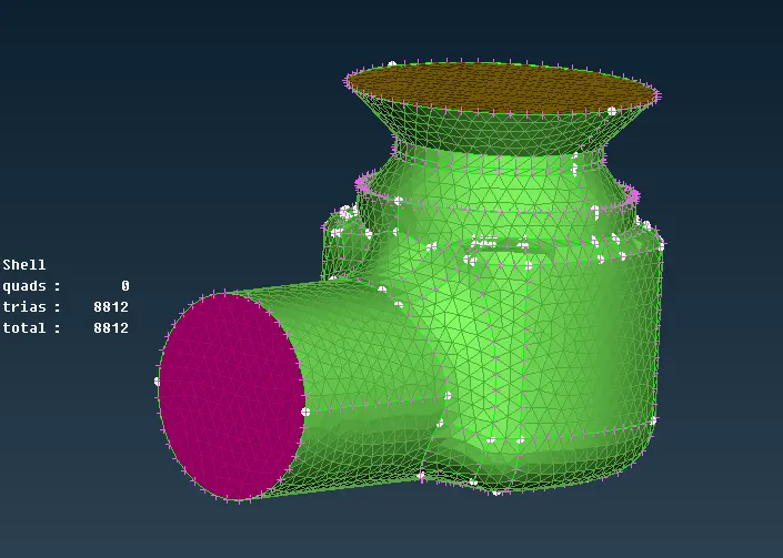
The below image is the final view of inside parts of the model after generation of mesh.
Conclusion:
- We have surface meshed the given model with three different lengths i.e., 1mm, 3 mm, 5mm.
- The above 3 cases it is observed that the case 1 with 1 mm target length has little to no defeaturing and has retained the geometry of all components.
- Hence case 3 is giving the best results. But it increases the computational time.
- To make computational time less each components needs to be meshed individually.